1
TROUBLESHOOTING
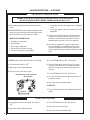
Note: Before troubleshooting the gas control system, Ensure external gas shut off valve, located at gas supply inlet, (and wall switch, iff applicable), is
in the “ON” position.
Important: Valve system troubleshooting should only be accomplished by a qualified service technician.
TROUBLESHOOTING GUIDE - MILLIVOLT GAS CONTROL SYSTEM
SYMPTOM
POSSIBLE CAUSES
1. Spark igniter will not light pilot after
repeated triggering of igniter button.
2. Pilot will not stay lit after
carefully following the lighting
instructions.
CORRECTIVE ACTION
A. Defective igniter
(no spark at electrode).
Check for spark at electrode and pilot; if no spark and
electrode wire is properly connected, replace igniter.
B. Defective or misaligned electrode at pilot
(spark at electrode).
Using a match, light pilot. If pilot lights, turn off pilot
and trigger the igniter button again. If pilot lights, an
improper gas mixture caused the bad lighting and a
longer purge period is recommended. If pilot will not
light – check gap at electrode and pilot – should be 1/8"
to have a strong spark. If gap measures 1/8", replace
pilot (see Figures 13 or 14 on Page 12).
C. Gas supply pressure errant.
Check inlet gas pressure. It should be within the limits
as marked on the rating plate.
D. Pilot orifice plugged.
Clean or replace pilot orifice.
A. Defective pilot generator
(thermocouple).
Check pilot flame, it must impinge on thermocouple
(see Figures 13 or 14 on Page 12). Clean and/or
adjust pilot for maximum flame impingement on
thermocouple. Ensure that the connection between
the valve and thermocouple are tight and secure.
3. Pilot burning, no gas to burner, Valve A. Wall switch or wires defective.
knob “ON,” and the (standard) burner
OFF/ON switch is “ON." Read important note below.
Check wall switch and wires for proper connections.
Jumper wire across terminals at wall switch, if burner
comes on, replace defective wall switch. If okay, jumper
wires across wall switch wires at valve, if burner comes
on, wires are faulty or connections are bad.
IMPORTANT NOTE: If an optional
*remote switch is used for burner
operation, if the standard burner
OFF/ON switch is still installed on
appliance it must be in the "OFF"
position.
B. Thermopile may not be generating sufficient millivolts.
Check thermopile with millivolt meter. Take reading
at thermopile terminals of gas valve. Should read
325 millivolts minimum with optional wall switch
“OFF.” Replace faulty thermopile if reading is below
specified minimum.
C. Plugged burner orifice.
Check burner orifice for blockage and remove.
*Optional remote switch kits - wall
switch, wall thermostat or remote
control.
D. OFF/ON Switch & *Remote Switch are in
the "ON" position resulting in excessive
resistance.
When turning on the burner using a *remote switch,
ensure that the standard OFF/ON switch is in the "OFF"
position. If both switches are in the ON position, it
may result in excessive resistance (& millivolt drainage) and the burner may not come on.
A. Pilot flame may be too low or blowing (high)
causing the pilot/valve safety to drop out.
Clean and/or adjust pilot flame for maximum flame
impingement on thermocouple (see Figures 13 or
14 on Page 12).
4. Frequent pilot/burner outage problem.
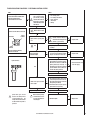
TROUBLESHOOTING GUIDE - ELECTRONIC IGNITION SYSTEM
SYMPTOM
1. Burner will not light.
POSSIBLE CAUSES
CORRECTIVE ACTION
A. Faulty Valve System.
See Below.
B. “OFF/ON” or wall switch defective.
Disconnect the two black wires from the wire nuts.
Test switch(s) for continuity with a multimeter. If
continuity is not indicated, switch(s) is defective and
must be replaced.
Note: Before replacing “OFF/ON” switch, Ensure to
check wiring for loose connections or broken wires
and repair as needed.
2. Burners come “ON,” then turns “OFF.”
20
A. Burner orifice plugged.
Check main burner orifice(s) for blockage. Clean
or replace.
B. Obstructed vent system.
Check vent system for obstructions.
NOTE: DIAGRAMS & ILLUSTRATIONS NOT TO SCALE.
20