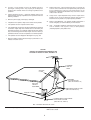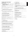
1
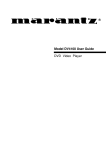
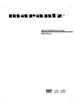
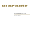
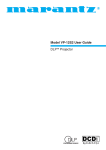
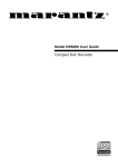
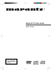
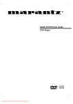
R
Model SR4320 User Guide
Receiver
CAUTION
RISK OF ELECTRIC SHOCK
DO NOT OPEN
CAUTION: TO REDUCE THE RISK OF ELECTRIC SHOCK,
DO NOT REMOVE COVER (OR BACK)
NO USER-SERVICEABLE PARTS INSIDE
REFER SERVICING TO QUALIFIED SERVICE PERSONNEL
The lightning flash with arrowhead symbol
within an equilateral triangle is intended to
alert the user to the presence of uninsulated
“dangerous voltage” within the product’s
enclosure that may be of sufficient magnitude
to constitute a risk of electric shock to persons.
The exclamation point within an equilateral
triangle is intended to alert the user to the
presence of important operating and
maintenance (servicing) instructions in the
literature accompanying the product.
WARNING
TO REDUCE THE RISK OF FIRE OR ELECTRIC SHOCK,
DO NOT EXPOSE THIS PRODUCT TO RAIN OR MOISTURE.
CAUTION: TO PREVENT ELECTRIC SHOCK, MATCH WIDE
BLADE OF PLUG TO WIDE SLOT, FULLY INSERT.
ATTENTION: POUR ÉVITER LES CHOC ÉLECTRIQUES,
INTRODUIRE LA LAME LA PLUS LARGE DE LA FICHE DANS LA
BORNE CORRESPONDANTE DE LA PRISE ET POUSSER
JUSQU’AU FOND.
NOTE TO CATV SYSTEM INSTALLER:
This reminder is provided to call the CATV (Cable-TV) system installer’s attention to Section 820-40 of the NEC which provides
guidelines for proper grounding and, in particular, specifies that the cable ground shall be connected to the grounding system of the
building, as close to the point of cable entry as practical.
NOTE:
- Reorient or relocate the receiving antenna.
This equipment has been tested and found to comply with
the limits for a Class B digital device, pursuant to Part 15
of the FCC Rules. These limits are designed to provide
reasonable protection against harmful interference in a
residential installation. This equipment generates, uses
and can radiate radio frequency energy and, if not
installed and used in accordance with the instructions,
may cause harmful interference to radio communications. However, there is no guarantee that interference
will not occur in a particular installation. If this equipment
does cause harmful interference to radio or television
reception, which can be determined by tuning the
equipment off and on, the user is encouraged to try to
correct the interference by one or more of the following
measures:
- Increase the separation between the equipment and receiver.
- Connect the equipment into an outlet on a circuit different
from that to which the receiver is connected.
- Consult the dealer or an experienced radio/TV technician for
help.
NOTE:
Changes or modifications not expressly approved by the
party responsible for compliance could void the user’s
authority to operate the equipment.
i
IMPORTANT SAFETY
INSTRUCTIONS
READ BEFORE OPERATING EQUIPMENT
This product was designed and manufactured to meet strict quality and
safety standards. There are, however, some installation and operation
precautions which you should be particularly aware of.
1.
Read Instructions – All the safety and operating instructions
should be read before the product is operated.
2.
Retain Instructions – The safety and operating instructions should
be retained for future reference.
3.
Heed Warnings – All warnings on the product and in the operating
instructions should be adhered to.
4.
Follow Instructions – All operating and use instructions should be
followed.
5.
Cleaning – Unplug this product from the wall outlet before
cleaning. Do not use liquid cleaners or aerosol cleaners. Use a
damp cloth for cleaning.
6.
Attachments – Do not use attachments not recommended by the
product manufacturer as they may cause hazards.
7.
Water and Moisture – Do not use this product near water-for
example, near a bath tub, wash bowl, kitchen sink, or laundry tub,
in a wet basement, or near a swimming pool, and the like.
8.
Accessories – Do not place this product on an unstable cart,
stand, tripod, bracket, or table. The product may fall, causing
serious injury to a child or adult, and serious damage to the
product. Use only with a cart, stand, tripod, bracket, or table
recommended by the manufacturer, or sold with the product. Any
mounting of the product should follow the manufacturer’s
instructions, and should use a mounting accessory recommended
by the manufacturer.
9.
10.
11.
12.
Grounding or Polarization – This product may be equipped with a
polarized alternating-current line plug (a plug having one blade
wider than the other). This plug will fit into the power outlet only
one way. This is a safety feature. If you are unable to insert the
plug fully into the outlet, try reversing the plug. If the plug should
still fail to fit, contact your electrician to replace your obsolete
outlet. Do not defeat the safety purpose of the polarized plug.
AC POLARIZED PLUG
13.
Power-Cord Protection – Power-supply cords should be routed so
that they are not likely to be walked on or pinched by items placed
upon or against them, paying particular attention to cords at plugs,
convenience receptacles, and the point where they exit from the
product.
14.
Protective Attachment Plug – The product is equipped with an
attachment plug having overload protection. This is a safety
feature. See Instruction Manual for replacement or resetting of
protective device. If replacement of the plug is required, be sure
the service technician has used a replacement plug specified by
the manufacturer that has the same overload protection as the
original plug.
15.
Outdoor Antenna Grounding – If an outside antenna or cable
system is connected to the product, be sure the antenna or cable
system is grounded so as to provide some protection against
voltage surges and built-up static charges. Article 810 of the
National Electrical Code, ANSI/NFPA 70, provides information
with regard to proper grounding of the mast and supporting
structure, grounding of the lead-in wire to an antenna discharge
unit, size of grounding conductors, location of antenna-discharge
unit, connection to grounding electrodes, and requirements for the
grounding electrode. See Figure 1.
16.
Lightning – For added protection for this product during a lightning
storm, or when it is left unattended and unused for long periods of
time, unplug it from the wall outlet and disconnect the antenna or
cable system. This will prevent damage to the product due to
lightning and power-line surges.
17.
Power Lines – An outside antenna system should not be located
in the vicinity of overhead power lines or other electric light or
power circuits, or where it can fall into such power lines or circuits.
When installing an outside antenna system, extreme care should
be taken to keep from touching such power lines or circuits as
contact with them might be fatal.
18.
Overloading – Do not overload wall outlets, extension cords, or
integral convenience receptacles as this can result in a risk of fire
or electric shock.
19.
Object and Liquid Entry – Never push objects of any kind into this
product through openings as they may touch dangerous voltage
points or short-out parts that could result in a fire or electric shock.
Never spill liquid of any kind on the product.
A product and cart combination should be moved with care. Quick
stops, excessive force, and uneven surfaces may cause the
product and cart combination to overturn.
Ventilation – Slots and openings in the cabinet are provided for
ventilation and to ensure reliable operation of the product and to
protect it from overheating, and these openings must not be
blocked or covered. The openings should never be blocked by
placing the product on a bed, sofa, rug, or other similar surface.
This product should not be placed in a built-in installation such as
a bookcase or rack unless proper ventilation is provided or the
manufacturer’s instructions have been adhered to.
Power Sources – This product should be operated only from the
type of power source indicated on the marking label. If you are not
sure of the type of power supply to your home, consult your
product dealer or local power company. For products intended to
operate from battery power, or other sources, refer to the
operating instructions.
ii
20.
Servicing – Do not attempt to service this product yourself as
opening or removing covers may expose you to dangerous
voltage or other hazards. Refer all servicing to qualified service
personnel.
21.
Damage Requiring Service – Unplug this product from the wall
outlet and refer servicing to qualified service personnel under the
following conditions:
a.
When the power-supply cord or plug is damaged.
b.
If liquid has been spilled, or objects have fallen into the product.
c.
If the product has been exposed to rain or water.
d.
If the product does not operate normally by following the operating
instructions. Adjust only those controls that are covered by the
operating instructions as an improper adjustment of other controls
may result in damage and will often require extensive work by a
qualified technician to restore the product to its normal operation.
e.
If the product has been dropped or damaged in any way, and
f.
When the product exhibits a distinct change in performance – this
indicates a need for service.
22.
Replacement Parts – When replacement parts are required, be
sure the service technician has used replacement parts specified
by the manufacturer or have the same characteristics as the
original part. Unauthorized substitutions may result in fire, electric
shock, or other hazards.
23.
Safety Check – Upon completion of any service or repairs to this
product, ask the service technician to perform safety checks to
determine that the product is in proper operating condition.
24.
Wall or Ceiling Mounting – The product should be mounted to a
wall or ceiling only as recommended by the manufacturer.
25.
Heat – The product should be situated away from heat sources
such as radiators, heat registers, stoves, or other products
(including amplifiers) that produce heat.
FIGURE 1
EXAMPLE OF ANTENNA GROUNDING AS PER
NATIONAL ELECTRICAL CODE, ANSI/NFPA 70
ANTENNA
LEAD IN
WIRE
GROUND
CLAMP
ANTENNA
DISCHARGE UNIT
(NEC SECTION 810-20)
ELECTRIC
SERVICE
EQUIPMENT
GROUNDING CONDUCTORS
(NEC SECTION 810-21)
GROUND CLAMPS
POWER SERVICE GROUNDING
ELECTRODE SYSTEM
(NEC ART 250, PART H)
NEC - NATIONAL ELECTRICAL CODE
This Class B digital apparatus complies with Canadian ICES-003.
Cet appareil numérique de la Classe B est conforme à la norme
NMB-003 du Canada.
iii
!2
t !5 y !1
!6
!0
!9
e
u
i !7
!3 !4
o
!8
RECEIVER SR4320
VOLUME
MULTI - JOG
SPEAKERS
A
B
DOWN
UP
DISPLAY OFF
CLEAR
MEMORY
JOG MODE
TUNING/PRESET
SPEAKERS
F/P
S-DIRECT
MODE
SLEEP
MUTE
STANDBY
POWER ON/STANDBY
PHONES
q
DVD
VCR
DSS
CDR/MD
w
z
CD
PHONO
TUNER
r
⁄2 ⁄3 ⁄4 ⁄5 ⁄6
c
TAPE
⁄7
ANTENNA
⁄9
AC OUTLETS
120V 60Hz
AM
DSS
IN
DVD
IN
VCR
IN
UNSWITCHED
120W 1A MAX
REMOTE
CONTROL
VIDEO
OUT
MONITOR
OUT
IN
GND
SWITCHED
120W 1A MAX
OUT
FM (75 Ω)
SPEAKER SYSTEMS
SYSTEM A : MINIMUM 8 OHMS
SYSTEM B : MINIMUM 8 OHMS
GND
SYSTEM B
R
PHONO
IN
CD
IN
CDR / MD
IN
OUT
IN
TAPE
OUT
DSS
IN
DVD
IN
IN
VCR
OUT
PRE
OUT
L
MAIN
IN
SERIAL NO.
L
R
R
AUDIO
xv b
z
x
MAIN
POWER
SOURCE
POWER
MUTE
1
2
3
b
4
5
6
.
⁄2
⁄3
7
8
9
SLEEP
DIMMER
CLEAR
F.DIRECT
T.MODE
DISP./RDS
PTY
DIRECTION
INPUT
REC
⁄8
MEMO
S-DIRECT
P.SCAN
SPKR A/B
BASS
TREBLE
0
TUNE/SEARCH
n m , . ⁄0 ⁄1
c
v
n
m
,
⁄0
⁄11
⁄5
⁄4
⁄7
PAUSE
⁄6
CH SKIP
CH SKIP
DVD
VCR
DSS
CDR
MD
TAPE
CD
PHONO
TUNER
AMP
VOLUME
L
SYSTEM A
⁄9
¤0
SYSTEM REMOTE CONTROLLER
RC4320SR
iv
⁄8
FEATURES ...................................................................................................................................................................... 2
ACCESSORIES ............................................................................................................................................................... 2
NAMES AND FUNCTIONS ............................................................................................................................................. 3
USING THE REMOTE CONTROL UNIT .................................................................................................................................................................. 6
CONNECTIONS ............................................................................................................................................................... 7
CONNECTING SPEAKERS ..................................................................................................................................................................................... 7
CONNECTING AUDIO COMPONENTS .................................................................................................................................................................. 8
CONNECTING VIDEO COMPONENTS .................................................................................................................................................................. 9
CONNECTING REMOTE CONTROL JACKS ........................................................................................................................................................ 10
CONNECTING THE ANTENNA TERMINALS ........................................................................................................................................................ 11
OPERATION .................................................................................................................................................................. 12
NORMAL PLAYBACK ............................................................................................................................................................................................. 12
BALANCE/TONE CONTROL ................................................................................................................................................................................. 12
TURNING THE SOUND OFF TEMPORARILY (MUTING) ..................................................................................................................................... 12
LISTENING WITH HEADPHONES ........................................................................................................................................................................ 12
LISTENING TO A DIFFERENT AUDIO SOURCE WHILE WATCHING A VIDEO SOURCE .................................................................................. 13
CHANGING THE BRIGHTNESS OF THE FRONT DISPLAY ................................................................................................................................ 13
SETTING THE SLEEP TIMER ............................................................................................................................................................................... 13
RECORDING OPERATION .................................................................................................................................................................................... 13
LISTENING TO THE RADIO ......................................................................................................................................... 14
MANUAL TUNING .................................................................................................................................................................................................. 14
AUTO TUNING ....................................................................................................................................................................................................... 14
FREQUENCY DIRECT CALL ................................................................................................................................................................................. 14
PRESET TUNING ................................................................................................................................................................................................... 15
TROUBLESHOOTING ................................................................................................................................................... 17
1
ENGLISH
TABLE OF CONTENTS
ENGLISH
FEATURES
ACCESSORIES
High quality full discrete power amplifier
Check the supplied accessories.
80W+80W (8 ohms, 20 Hz – 20 kHz, 0.08% THD)
Remote control unit (RC4320SR)
Speaker A/B switching
You can switch the speaker A/B via remote control unit.
Three A/V inputs (DVD, DSS and VCR)
One A/V output (VCR) and one video monitor output
Seven audio inputs and three audio outputs
Built in PHONO equalizer (MM)
Batteries (AAA, R03, UM-4) 2 pcs
Simulcast playback video signal of video source with audio
source
30 station AM/FM random preset memory
Bass and treble tone controls
Source direct
FM Antenna
You can bypass the tone and balance controls, routing the audio
signal directly to provide the pure sound quality.
PRE OUT and MAIN IN jacks
Sleep timer
Banana plug compatible speaker terminals
Dimmer control via remote control unit
AM Loop Antenna
Warranty Card
2
Press this button to clear the tuner preset station.
FRONT PANEL
!1 MEMORY button
q P OW E R O N / S TA N D B Y s w i t ch a n d
STANDBY indicator
Press this button to enter the tuner preset memory numbers and station
names.
When this switch is pressed once, the unit turns ON and display appear
on the display panel.
When pressed again, the unit enters the standby mode and the
STANDBY indicator lights.
!2 TUNING/PRESET up ( ) and down ( )
buttons
During reception of AM or FM, you can scan the other frequencies or
select another preset station pressing these buttons.
To turn the power ON from standby mode, press any of the function
buttons of the main unit or the MAIN POWER button of the remote control
unit.
When the STANDBY indicator lights up, the apparatus is NOT
disconnected from the AC supply mains.
!3 F (Frequency)/P (Preset) button
During reception of AM or FM, you can change the function of the UP/
DOWN buttons for scanning frequencies or selecting preset stations by
pressing this button.
w PHONES jack for stereo headphones
Conventional dynamic headphones can be plugged in here.
!4 MODE button
Note:
When using headphones, the speaker A and/or B are switched
automatically to OFF and the sound from the speakers is muted.
The speaker A and/or B return to the previous setting as soon as the
plug is removed from the jack.
Press this button to select AUTO mode or MONO mode when the FM
band is selected.
!5 SPEAKERS indicator
These indicators show active speaker system(s).
e MULTI-JOG control knob
!6 DISPLAY OFF indicator
Turn the control (BALANCE, TREBLE or BASS) knob selected by the
JOG MODE button to adjust (the balance, treble or bass).
Lights up when you select “Display off”.
r Function selector buttons
!7 Infrared sensor
These buttons are used to select the sources. The selected source name
will be displayed on the front display.
The video function selector, such as DVD, VCR and DSS, selects video
and audio simultaneously.
This sensor receives infrared signals from the remote control unit.
!8 VOLUME control knob
Adjusts the overall sound level. Turning the control clockwise increases
the sound level.
Audio function sources such as CDR/MD, TAPE, CD, PHONO and
TUNER may be selected in conjunction with a Video source.
This feature (Sound Injection) combines a sound from one source with
a picture from another.
Choose the video source first, and then choose a different audio source
to activate this function.
!9 Display
t JOG MODE button
Press this button to adjust BALANCE and TONE CONTROL (BASS/
TREBLE). Each time this button is pressed, the mode changes as
BAL (BALANCE) → TRE (TREBLE) → BASS → BAL (BALANCE). If this
button is pressed in Source Direct Mode, Source Direct is cancelled.
y SPEAKERS (system A or B) button
Press this button to select speaker system(s) to use. Each time this
button is pressed, the selected speaker(s) is changed as, only A is on
→ only B is on → both A and B are on → both A and B are off. The
corresponding indicator(s) of the active speaker system(s) light up.
If headphones are connected, both A and B are set off automatically.
u S (Source)-DIRECT button
When this button is pressed, the audio signal will bypass the balance
and tone control circuit to provide the pure sound quality.
To return not to bypass the balance and tone control circuit, press
S-DIRECT button again or press JOG MODE button.
i SLEEP (Sleep timer) button
This button is used for setting the sleep timer.
o MUTE button
Press this button to mute the output to the speakers. Press it again to
return to the previous volume level.
3
ENGLISH
!0 CLEAR button
NAMES AND FUNCTIONS
ENGLISH
DISPLAY
REAR PANEL
All connections to the rear panel should be made with entire power off
to the system. To avoid miss-connection, it is advisable to connect one
cable at a time between the different components. This is the safest
way to avoid cross-connecting channels or mix up signal inputs with
outputs.
a TUNED indicator
This indicator illuminates when a station is being received with sufficient
signal strength to provide acceptable listening quality.
b STEREO indicator
z Antenna terminals
This indicator illuminates when an FM station is being tuned in stereo
condition.
FM antenna terminal
For connecting the supplied FM antenna or for connecting an external
FM antenna with a coaxial cable, or for connecting a cable network.
c MEMORY indicator
When the MEMORY button is pressed, this indicator blinks for about 5
seconds.
AM antenna and ground terminal
For connecting the supplied AM loop antenna. Use the terminals marked
“AM” and “GND”.
The supplied AM loop antenna will provide good AM reception in most
areas. Position the loop antenna to the best reception.
d SLEEP indicator
This indicator lights up while the sleep timer function is in use.
x PHONO audio input jacks
e Frequency/Character display
Connect the audio output jacks of an analog turntable to these jacks.
This displays the selected station frequency or the corresponding words
when selecting a program source.
c GND (ground) terminal
f Preset number display
Connect the grounding wire from the analog turntable to this terminal.
Shows the selected preset number.
v CD audio input jacks
Connect to the CD’s audio output jacks.
b CDR/MD audio input/output jacks
Connect the audio output (PLAY) jack of the CD recorder/MD deck to
the IN jack, and connect the audio input (REC.) jack to the OUT jack.
n TAPE audio input/output jacks
Connect the audio output (PLAY) jack of the cassette deck to the IN
jack, and connect the audio input (REC.) jack to the OUT jack.
m DSS audio input jacks
Connect to the satellite tuner’s audio output jacks.
, DVD audio input jacks
Connect to the DVD’s audio output jacks.
. VCR audio input/output jacks
Connect the audio output (PLAY) jack of the VCR to the IN jack, and
connect the audio input (REC.) jack to the OUT jack.
⁄0 PRE OUT jacks
Use these jacks to connect an extension power amplifier or graphic
equalizer.
When a graphic equalizer is to be connected, connect its input jacks
with the PRE OUT jacks on this unit.
When not used, leave these jacks connected with the supplied
connecting pins.
⁄1 MAIN IN jacks
Use these jacks to connect an extension pre amplifier or graphic
equalizer.
When a graphic equalizer is to be connected, connect its output jacks
with the MAIN IN jacks on this unit.
When not used, leave these jacks connected with the supplied
connecting pins.
4
REMOTE CONTROL UNIT
Connect to the satellite tuner’s video output jack.
The supplied remote control unit can be used to control a Marantz audio/
visual component such as a DVD player, CD player.
The POWER button, numeric buttons and control buttons are used in
common across different input source components.
The input source controlled with the remote control unit changes when
one of the input selector buttons on the remote control unit is pressed.
⁄3 DVD video input jack
Connect to the DVD’s video output jack.
⁄4 VCR video input/output jacks
Connect to the TV’s video input (VIDEO IN) jack.
• Example
To select the DVD as the input source and play the DVD player.
Press the DVD button twice within 2 seconds. The input selector of
the SR4320 is switched to DVD and the remote control unit is set for
control of the DVD player.
Press the PLAY button on the remote control unit.
⁄6 REMOTE CONTROL IN/OUT jacks
z Infrared window
Connect to other Marantz component equipped with REMOTE
CONTROL jacks.
Outputs infrared control signals.
Connect the video output (PLAY) jack of the VCR to the IN jack, and
connect the video input (REC.) jack to the OUT jack.
⁄5 MONITOR output jack
x MAIN POWER button
⁄7 AC OUTLETS
Press to switch the power of the SR4320 ON or STANDBY.
Connect the AC power cable of a CD player, cassette deck, etc., of
your system to these outlets.
The power supply from switched outlet is interlocked with the POWER
switch of the receiver.
The maximum power consumption of the connected components must
not exceed the following limit:
SWITCHED
120 WATT MAX.
UNSWITCHED 120 WATT MAX.
c Transmitting indicator
Lights up during a button is pressed and an infrared signal is being
sent.
v SOURCE POWER button
Press to switch the power of the source component after pressing the
function selector button.
⁄8 Speaker terminals
b Numeric buttons 0 to 9
Connect your speaker system(s) to these terminals. There are two sets
of terminals, so you can connect either A and/or B speaker systems.
These buttons are used to enter figures in the selection of a tuner preset
station or to select a CD track number, etc.
⁄9 AC power cord
n MUTE button
Plug into AC120V household outlet.
Press this button decrease the sound temporarily.
Press this button again to return to the previous sound level.
m SLEEP button
This button is used for setting the sleep timer.
, DIMMER button
When this button is pressed once, the display is dimmed. When this
button is pressed twice, the display is turned off and the “DISPLAY OFF”
indicator lights up.
Press this button again to turn on the display again.
. CLEAR button
This button is used to cancel for certain memory or programming
operations.
⁄0 MEMO (Memory) button
Memory enables button for various preset functions.
⁄1 S (Source)-DIRECT button
When this button is pressed, the audio signal will bypass the balance
and tone control circuit to provide the pure sound quality.
⁄2 F.DIRECT button
(when tuner mode is selected)
Press this button to change tuner mode to Frequency Direct Call mode.
You can call your desired frequency with numeric button of the remote
control unit in this mode.
⁄3 T.MODE button
(when tuner mode is selected)
Press this button to select the AUTO mode or MONO mode when the
FM band is selected.
5
ENGLISH
⁄2 DSS video input jack
ENGLISH
⁄4 P.SCAN button
(when tuner mode is selected)
USING THE REMOTE CONTROL UNIT
This button is used to start preset scan when tuner mode is selected in
SR4320.
Remote control operational range
The distance between the transmitter of the remote control unit and the
IR SENSOR of the SR4320 should be less than about 5 meters.
If the transmitter is pointed to a direction other than the IR SENSOR or if
there is an obstacle between them, remote control may not be possible.
⁄5 SPKR A/B button
Press the button to select the speaker system (or systems) which is to
be used. Each time it is pressed, the setting is selected in the following
sequence in turn: A only ON → B only ON → A and B ON → A and B
OFF → A only ON, and so on. The speaker indicator (or indicators)
corresponding to the speaker (or speakers) which has been set to the
active status lights.
When headphones have been connected, speakers A and B are
automatically set to OFF.
5m
⁄6 BASS up ( )/down ( ) buttons
These buttons are used to adjust the tone control of low frequency sound.
60
⁄7 TREBLE up ( )/down ( ) buttons
These buttons are used to adjust the tone control of high frequency
sound.
⁄8 Control buttons
Preparing the remote control unit
The life of the batteries used with the remote control unit is about
4 months with normal use. Also be sure to replace batteries earlier when
you notice that they are getting weak.
1 Remove the back cover.
These buttons are used when operating the CD player, TAPE deck, etc.
The function of these buttons are dependent on the function button
selected.
For the controllable functions of each input function, please refer to
following table.
VCR
CDR
Display
disc
info.
DVD
---
Switch
Display
info.
PTY
---
---
DIRECTION
---
---
DISP/RDS
INPUT
REC
TUNE/SEARCH
TUNE/SEARCH
PAUSE
CH SKIP
CH SKIP
MD
TAPE
CD
TUNER
---
---
Scroll
disc
info.
RDS*5
---
---
---
---
PTY*5
---
---
Direction
---
---
Select the input of the monitor
---
Record Record Record Record
---
---
FR*1
FR*1
FR*1
FR*1
FR*1
FR*1
Back
search
2
2
2
2
2
2
Search
FF*
FF*
FF*
FF*
FF*
FF*
Pause
Pause
Pause
Pause
Pause
Pause
Play
Play
Play
Play
Play
Play
---
2
Insert the new batteries (AAA type) with correct (+) and (–) polarity.
3
Close until it clicks shut.
---
Next
Next
Next
Next
Next
Next
P.Memo
Up*3
Prev.
Prev.
Prev.
Prev.
Prev.
Prev.
P.Memo
Down*4
Stop
Stop
Stop
Stop
Stop
Stop
---
*1 FR: Fast rewind
*2 FF: Fast forward
*3 P.Memo Up: Scan the preset station memory Up
*4 P.Memo Down: Scan the preset station memory Down
*5 These functions cannot be used for SR4320.
⁄9 Input selector buttons/Function selector
buttons (audio/video input)
Press one of these buttons once or twice to select a particular source
component. For example, to set the receiver to the DVD input, press
the DVD button twice within 2 seconds.
¤0 VOLUME up ( )/down ( ) buttons
Press to adjust the volume control of SR4320.
6
ENGLISH
CONNECTIONS
System B
Right
Left
CONNECTING SPEAKERS
ANTENNA
AC OUTLETS
120V 60Hz
AM
DSS
IN
DVD
IN
VCR
IN
UNSWITCHED
120W 1A MAX
REMOTE
CONTROL
VIDEO
OUT
MONITOR
OUT
IN
GND
SWITCHED
120W 1A MAX
OUT
FM (75 Ω)
SPEAKER SYSTEMS
SYSTEM A : MINIMUM 8 OHMS
SYSTEM B : MINIMUM 8 OHMS
GND
SYSTEM B
R
PHONO
IN
CDR / MD
IN
OUT
CD
IN
IN
TAPE
OUT
DSS
IN
DVD
IN
IN
VCR
OUT
PRE
OUT
L
MAIN
IN
SERIAL NO.
L
R
R
AUDIO
L
SYSTEM A
Right
Left
System A
Connecting speaker wire
1
Strip away approx. 3/8 inch (10 mm) of wire insulation.
Connecting banana plug
Banana plug connections are also
possible.
Tighten the knob by turning
clockwise and then insert the
banana plug.
10 mm
2
Twist the exposed wire ends very tight to prevent short circuits.
3
Loosen the knob by turning counterclockwise.
4
Insert one bare wire into the hole in the side of each terminal.
Banana plug
CAUTION
• Be sure to use speakers with the specified impedance shown on
the rear panel of this unit.
• To prevent damage to circuitry, do not let
the bare speaker wires touch each other
and do not let them touch any metal part
of this unit.
• Do not touch the speaker terminals when
the power is on. It may cause electric
shocks.
• Do not connect more than one speaker cable to one speaker
terminal. Doing so may damage this unit.
Note:
Be sure to connect the positive and negative cables for the speaker
properly. If they are miss-connected, signal phase will be reversed
and the sound quality will be corrupted.
5
Tighten the knob by turning clockwise to secure the wire.
7
ENGLISH
CONNECTING AUDIO COMPONENTS
The output audio signal from the TAPE OUT jack and the CD-R/MD OUT jack is the sound source currently selected.
Graphic equalizer
or
processor
Tape deck
OUT
IN
L
OUT
L
R
R
IN
L
L
R
R
R L
R L
R L R L
R L
L R
L R
L R
ANTENNA
AC OUTLETS
120V 60Hz
DSS
IN
DVD
IN
VCR
IN
UNSWITCHED
120W 1A MAX
REMOTE
CONTROL
VIDEO
AM
OUT
MONITOR
OUT
IN
GND
SWITCHED
120W 1A MAX
OUT
FM (75 Ω)
GND
SPEAKER SYSTEMS
SYSTEM A : MINIMUM 8 OHMS
SYSTEM B : MINIMUM 8 OHMS
MODEL NO
SYSTEM B
AC 120V
R
PHONO
IN
CD
IN
CDR / MD
IN
OUT
IN
TAPE
OUT
DSS
IN
DVD
IN
IN
VCR
OUT
PRE
OUT
L
MADE I
MAIN
IN
SERIAL NO.
L
R
R
AUDIO
L
SYSTEM A
L R L R L R L R
L R
L R
L R
L R
Turn table
CD recorder
CD player
L
L
R
L
R
OUT
L
R
OUT
R
OUT
CAUTION
Do not connect this unit and other components to mains power until
all connections between components have been completed.
IN
Connecting PRE OUT/MAIN IN jacks
Connecting with external power amplifier
This receiver has enough power for normal listening but PRE OUT jacks
are prepared to connect external power amplifiers for higher power
output. In such a case, connect these jacks to the MAIN IN jacks or
AUX IN jacks of the power amplifier.
Notes:
• Insert all plugs and connectors securely. Incomplete connections
will result in the generation of noise.
• Be sure to connect the left and right channels properly.
Red connectors are used for the R (right) channel, and white
connectors are used for L (left) channel.
• Be sure to connect input and output properly.
• Refer to the instructions for each component to be connected to
this unit.
• Do not bind audio/video connection cables with power cords and
speaker cables. It will result in generating hum or other noise.
• Remove the short pin when using the PRE OUT, MAIN IN terminals.
Connecting with graphic equalizer
Use PRE OUT and MAIN IN jacks to connect a graphic equalizer or
other analog audio processor.
Note:
When not used, leave these jacks connected with the supplied
connecting pins.
8
VCR
AUDIO
OUT
L R
ENGLISH
CONNECTING VIDEO COMPONENTS
Monitor
AUDIO VIDEO
IN
OUT IN
VIDEO
IN
L R
CVBS
L
R
L R
L
R
L R
ANTENNA
AC OUTLETS
120V 60Hz
DSS
IN
DVD
IN
VCR
IN
UNSWITCHED
120W 1A MAX
REMOTE
CONTROL
VIDEO
AM
OUT
MONITOR
OUT
IN
GND
SWITCHED
120W 1A MAX
OUT
FM (75 Ω)
SPEAKER SYSTEMS
SYSTEM A : MINIMUM 8 OHMS
SYSTEM B : MINIMUM 8 OHMS
GND
SYSTEM B
R
PHONO
IN
CD
IN
CDR / MD
IN
OUT
IN
TAPE
OUT
DSS
IN
DVD
IN
IN
VCR
OUT
PRE
OUT
L
MAIN
IN
L
R
R
AUDIO
L R
L
SYSTEM A
R L
L R
L R
DVD player
AUDIO VIDEO
OUT
OUT
L R
AUDIO VIDEO
OUT
OUT
L R
Notes:
• Insert all plugs and connectors securely. Incomplete connections will result in the generation of noise.
• Be sure to connect the left and right channels properly.
Red connectors are used for the R (right) channel, and white connectors are used for L (left) channel.
• Be sure to connect input and output of video signal properly.
9
Satellite tuner
ENGLISH
CONNECTING REMOTE CONTROL JACKS
You can control other Marantz products through this unit with the remote control unit by connecting REMOTE CONTROL terminals on each unit.
The signal transmitted from the remote control unit is received by the remote sensor on this unit then the signal is sent to the connected device through
this terminal.
Therefore you need to aim the remote signal only to this unit.
ANTENNA
AC OUTLETS
120V 60Hz
DSS
IN
DVD
IN
VCR
IN
UNSWITCHED
120W 1A MAX
REMOTE
CONTROL
VIDEO
AM
OUT
MONITOR
OUT
IN
GND
SWITCHED
120W 1A MAX
OUT
FM (75 ‰)
GND
SPEAKER SYSTEMS
SYSTEM A : MINIMUM 8 OHMS
SYSTEM B : MINIMUM 8 OHMS
MO
SYSTEM B
A
R
PHONO
IN
CD
IN
CDR / MD
IN
OUT
IN
TAPE
OUT
DSS
IN
DVD
IN
IN
VCR
OUT
PRE
OUT
L
MAIN
IN
SERIA
L
MODE
R
SERI N
R
AUDIO
REMOTE
CONTROL
CD recorder
REMOTE
CONTROL
MD deck
REMOTE
CONTROL
IN
IN
IN
OUT
OUT
OUT
EXTERNAL INTERNAL
L
SYSTEM A
EXTERNAL INTERNAL
Set the REMOTE CONTROL switch on the units other than this unit to EXT. (EXTERNAL) for this feature.
10
CD player
EXTERNAL INTERNAL
AM external
antenna
AM loop
antenna
FM external
antenna
FM antenna
ANTENNA
ENGLISH
CONNECTING THE ANTENNA TERMINALS
AC OUTLETS
120V 60Hz
DSS
IN
DVD
IN
VCR
IN
UNSWITCHED
120W 1A MAX
REMOTE
CONTROL
VIDEO
AM
OUT
MONITOR
OUT
IN
GND
SWITCHED
120W 1A MAX
OUT
FM (75 Ω)
SPEAKER SYSTEMS
SYSTEM A : MINIMUM 8 OHMS
SYSTEM B : MINIMUM 8 OHMS
GND
SYSTEM B
R
PHONO
IN
CD
IN
CDR / MD
IN
OUT
IN
TAPE
OUT
DSS
IN
DVD
IN
IN
VCR
OUT
PRE
OUT
L
MAIN
IN
SERIAL NO.
L
R
R
AUDIO
Assembling the AM loop antenna
1
Release the vinyl tie and take out the connection line.
2
Bend the base part in the reverse direction.
L
SYSTEM A
Connecting the supplied antennas
Connecting the supplied FM antenna
The supplied FM antenna is for indoor use only.
During use, extend the antenna and move it in various directions until
the clearest signal is received.
Fix it with push pins or similar implements in the position that will cause
the least amount of distortion.
If you experience poor reception quality, an external antenna may
improve the quality.
Connecting an FM external antenna
Notes:
• Keep the antenna away from noise sources (neon signs, busy
roads, etc.).
• Do not put the antenna close to power lines. Keep it well away
from power lines, transformers, etc.
• To avoid the risk of lightning and electrical shock, grounding is
necessary.
Connecting an AM external antenna
3
4
An external antenna will be more effective if it is stretched horizontally
above a window or outside.
Insert the hook at the bottom of the loop part into the slot at the
base part.
Notes:
• Do not remove the AM loop antenna.
• To avoid the risk of lightning and electrical shock, grounding is
necessary.
Place the antenna on stable surface.
11
ENGLISH
OPERATION
BALANCE/TONE CONTROL
NORMAL PLAYBACK
If necessary, adjust the balance and tone control as below.
RECEIVER SR4320
VOLUME
MULTI - JOG
RECEIVER SR4320
SPEAKERS
A
B
DOWN
UP
MULTI - JOG
DISPLAY OFF
CLEAR
MEMORY
JOG MODE
TUNING/PRESET
SPEAKERS
F/P
S-DIRECT
MODE
SLEEP
MUTE
STANDBY
POWER ON/STANDBY
SPEAKERS
PHONES
DVD
VCR
DSS
CDR/MD
TAPE
CD
PHONO
A
TUNER
B
DISPLAY OFF
CLEAR
JOG MODE
1
2
4
MAIN
POWER
TUNING/PRESET
SPEAKERS
S-DIRECT
STANDBY
POWER ON/STANDBY
1
MEMORY
PHONES
DVD
VCR
DSS
CDR/MD
TAP
SOURCE
POWER
MUTE
1
2
3
SLEEP
4
5
7
8
6
2
DIMMER
CLEAR
S-DIRECT
P.SCAN
SPKR A/B
BASS
TREBLE
1
0
F.DIRECT
T.MODE
DISP./RDS
PTY
DIRECTION
INPUT
REC
TUNE/SEARCH
CH SKIP
2
2
PAUSE
CH SKIP
DVD
VCR
DSS
CDR
MD
TAPE
CD
PHONO
TUNER
AMP
VOLUME
4
You can control the tone (BASS/TREBLE) by remote control unit directly.
TURNING THE SOUND OFF TEMPORARILY
(MUTING)
Press the POWER button to turn on the power.
Press the function select button to select an input source.
Note:
In case of remote control operation, press one of the function button
twice within 2 seconds to select the function.
3
4
Press the JOG MODE button on the front panel to select your
desired control.
Each time the JOG MODE button is pressed, the mode changes
as BAL (BALANCE) → TRE (TREBLE) → BASS → BAL
(BALANCE).
Turn the MULTI-JOG knob to adjust the control.
BALANCE: Turn the knob clockwise to decrease volume of the left
channel and turn the knob counter-clockwise to decrease
volume of the right channel.
TREBLE:
Turning the knob clockwise enhance the high frequency
band, while turning counterclockwise attenuates the high
frequency band.
BASS:
Turning the knob clockwise enhance the low frequency
band, while turning counterclockwise attenuates the low
frequency band.
SYSTEM REMOTE CONTROLLER
RC4320SR
1
2
1
9
MEMO
Press the MUTE button to turn off the audio output temporarily.
You can cancel mute to press MUTE button again or press VOLUME
or button on the remote control unit.
Muting is not released even when the VOLUME control knob on the
main unit is rotated.
Start playback on the source component.
Adjust the volume level using the Volume control knob on the front
panel or pressing the volume buttons on the remote control unit.
LISTENING WITH HEADPHONES
Connect the headphones with a standard stereo plug to the PHONES
jack on the front panel.
When you connect headphones, no sound will be heard from the
speaker. When the headphones are unplugged, this unit returns to its
original listening mode.
12
1
2
RECORDING OPERATION
1
2
Select one of the following video sources.
DVD, DSS or VCR
Next, select one of the following audio sources with remote control
unit.
TUNER, PHONO, CD, TAPE or CDR/MD
3
4
Notes:
• When this unit is in the standby mode or turn off, you cannot record
between other components connected to this unit.
• The setting of BALANCE, BASS, TREBLE, VOLUME, MUTE does
not affect the recorded material.
• A given input source does not output on the same OUT channel
(For example, the signal input from VCR IN is not output on VCR
OUT).
• If you playback a video source that uses scrambled or encoded
signals to prevent it from being dubbed, the picture itself may be
disturbed due to those signals.
CHANGING THE BRIGHTNESS OF THE
FRONT DISPLAY
The display brightness changes in three steps (max, min and off) by
pressing the DIMMER button on the remote control unit repeatedly.
During display off mode, the DISPLAY OFF indicator lights up.
SETTING THE SLEEP TIMER
Set the sleep timer while the power is turned on.
1 Turn the power ON and press the SLEEP button on the remote
control unit to enter the sleep timer mode.
2 Press the SLEEP button the number of times to set the desired
sleep time in minutes.
Each press of the SLEEP button, changes the display in the
following order.
10
20
30
40
50
OF (off)
90
80
70
60
Press the POWER button to turn on the power.
Press the function select button of the source you want to record
from.
Start playback (or select a broadcast station) on the source
component.
Start recording on the recording component. For instructions, refer
to the component’s instructions.
The unit will be in the standby mode in the number of minutes
indicated.
• While the sleep timer is activated, the remaining time can be displayed
for approximately 2 seconds by pressing the SLEEP button.
• To cancel the sleep timer, press SLEEP button several times until
“SLEEP OF” (SLEEP OFF) appears on the display.
13
ENGLISH
LISTENING TO A DIFFERENT AUDIO
SOURCE WHILE WATCHING A VIDEO
SOURCE
ENGLISH
LISTENING TO THE RADIO
MANUAL TUNING
AUTO TUNING
4
3
1
2
3
SPEAKERS
4
A
B
DOWN
DISPLAY OFF
CLEAR
JOG MODE
MEMORY
TUNING/PRESET
SPEAKERS
F/P
S-DIRECT
MODE
SLEEP
To select the tuner as the source, press the TUNER button on the
front panel or the TUNER button on the remote control unit.
Press the TUNER button on the front panel or press the TUNER
button on the remote control unit to select the desired frequency
band if required.
In the preset tuning mode, press the F/P button on the front panel
to change to the manual tuning mode.
Press the TUNING/PRESET or button on the front panel or
TUNE/SEARCH
or
button on the remote control unit for
more than 1 second to start the Auto tuning function.
MUTE
FREQUENCY DIRECT CALL
DVD
VCR
DSS
CDR/MD
TAPE
CD
PHONO
TUNER
1
2
3
1,2
DIRECTION
REC
INPUT
BASS
PAUSE
TUNE/SEARCH
CH SKIP
CH SKIP
DVD
VCR
DSS
CDR
MD
TAPE
CD
PHONO
TUNER
SYSTEM REMOTE CONTROLLER
RC4320SR
1
2
3
4
4
TREBLE
4
AMP
VOLUME
1,2
To select the tuner as the source, press the TUNER button on the
front panel or the TUNER button on the remote control unit.
Press the TUNER button on the front panel or press the TUNER
button on the remote control unit to select the desired frequency
band if required.
In the preset tuning mode, press the F/P button on the front panel
to change to the manual tuning mode.
Press the TUNING/PRESET or button on the front panel or
press the TUNE/SEARCH
or
button on the remote control
unit to change the frequency.
When FM has been selected, the current mode is displayed when the
MODE button on the front panel or the T.MODE button on the remote
control unit is pressed once, and the screen changes when the same
button is pressed again while the current mode is displayed.
When “AUTO” mode is selected, “AUTO” appears on the front display
about 2 seconds. FM stations that broadcast in stereo will be received
in stereo and the “STEREO” indicator lights up.
If the signal is weak, it may be impossible to tune into the station in
stereo. In such as a case, press the MODE button on the front panel or
press the T.MODE button on the remote control unit. “MONO” appears
on the front display about 2 seconds and the program is received as
the monaural mode.
To return to stereo, press the MODE button or T.MODE button again.
Some noise may be heard, but the sound will not cut in and out as it
would if stereo was selected.
14
Press F.DIRECT button in the tuner mode on the remote control
unit.
Display shows “F-DIR-IN”.
Input your desired frequency with ten key buttons on the remote
control unit.
E.g.) 98.1 MHz: Press 9, 8, 1 and 0
It displays fixed frequency and broadcast is received.
Auto Presetting
With this unit you can preset up to 30 FM/AM stations in any order. For
each station, you can memorize the frequency and reception mode if
desired.
2, 4
This function automatically scans the AM and FM band and enters all
stations with sufficient signal strength into the memory.
3
1
Select the FM band with the TUNER button.
2
Tune in the lowest receivable frequency.
3
Press and hold down the MEMORY button and TUNING/PRESET
button simutaneously, auto presetting will start.
Each time the tuner finds a station, the scanning will pause and
memory.
Operation stops automatically when all 30 preset memory positions
are filled or when auto scanning attains the highest end of all bands.
To stop the auto preset function at anytime, press the CLEAR
button.
4
5
SPEAKERS
A
B
DOWN
DISPLAY OFF
CLEAR
JOG MODE
DVD
MEMORY
TUNING/PRESET
SPEAKERS
VCR
F/P
S-DIRECT
DSS
MODE
SLEEP
CDR/MD
TAPE
CD
Note:
If Auto Presetting is interrupted by pressing the CLEAR button, the
memory which has already been set is kept still.
MUTE
PHONO
TUNER
Recalling a Preset Station
2
1
DIMMER
7
8
CLEAR
9
MEMO
S-DIRECT
P.SCAN
SPKR A/B
BASS
TREBLE
2,4
0
F.DIRECT
T.MODE
DISP./RDS
PTY
DIRECTION
INPUT
SPEAKERS
A
B
DOWN
DISPLAY OFF
REC
TUNE/SEARCH
PAUSE
CLEAR
CH SKIP
CH SKIP
3
JOG MODE
DVD
MEMORY
TUNING/PRESET
SPEAKERS
VCR
DSS
F/P
S-DIRECT
CDR/MD
MODE
SLEEP
TAPE
CD
MUTE
PHONO
TUNER
Manual Presetting
1
2
3
4
Refer to the “Manual tuning”, “Auto tuning” or “Frequency direct
call” section (P.14) above to tune in a desired station.
Press the MEMORY button on the front panel or press the MEMO
button on the remote control unit.
While “MEMORY” is still blinking (approx. 5 seconds ), select the
desired preset number by pressing TUNING/PRESET
or
button on the front panel or TUNE/SEARCH
or
button on
the remote control unit.
Then, press the MEMORY button or MEMO button again to store
the station in the preset memory.
When a number has been properly input, “MEMORY” indicator
stops blinking and goes out. The station is now stored in the
specified preset memory location.
1
2
Press the F/P button on the front panel to change the display to
preset.
Select the desired preset station by pressing the TUNING/PRESET
or button on the front panel or press the CH SKIP button on
the remote control unit.
Notes:
• To directly access the preset stations using the ten key buttons on
the remote control unit, select the desired preset station by entering
one or two digits using the ten key buttons.
• To return to the Manual Tuning mode, press the F/P button on the
front panel.
Notes:
• To preset the station in the preset memory, press the ten key buttons
on the remote control unit.
• If a preset number already used is selected, the currently tuned
station is stored with the preset number and the formerly stored
station with the number is erased without any warning.
15
ENGLISH
PRESET TUNING
Preset Scan Tuning
ENGLISH
MAIN
POWER
MAIN
POWER
MUTE
SOURCE
POWER
3
MUTE
1
2
3
4
5
6
1
2
3
4
5
6
SLEEP
DIMMER
SLEEP
7
8
CLEAR
DIMMER
7
8
CLEAR
9
MEMO
F.DIRECT
T.MODE
DISP./RDS
PTY
DIRECTION
INPUT
P.SCAN
BASS
1
TREBLE
PAUSE
CH SKIP
DVD
VCR
DSS
CDR
MD
TAPE
CD
PHONO
TUNER
AMP
VOLUME
SYSTEM REMOTE CONTROLLER
RC4320SR
4
Press the P.SCAN button on the remote control unit. (The preset
station with the smallest preset number is recalled first. If no stations
have been preset, CH “00” blinks in the display and the unit returns
to the previous mode.)
Preset stations are recalled in sequence for 5 seconds each. Preset
numbers that do not contain stations are skipped.
You can skip to the next preset station by pressing the CH SKIP
button on the remote control unit.
When the desired preset station received, cancel the preset scan
operation by pressing the CH SKIP
button or the CLEAR
button.
You can remove preset stations from memory using the following
procedure.
2
Recall the preset number to be cleared with the method described
in “Recalling a Preset Station”.
Press the MEMORY button on the front panel or MEMO button on
the remote control unit, “MEMORY” blinks in the display for
5 seconds. While “MEMORY” is still blinking, press the CLEAR
button.
“CLEAR” appears on the display to indicate that the specified
preset number has been cleared.
1
The station name preset function allows the name of each preset channel
to be entered using alphanumeric characters. The Station Name button
is valid only in the tuner mode. Before station name preset operation,
store stations with the preset memory operation.
3
SPEAKERS
A
B
DOWN
DISPLAY OFF
CLEAR
JOG MODE
DVD
MEMORY
TUNING/PRESET
SPEAKERS
VCR
DSS
F/P
S-DIRECT
CDR/MD
SPKR A/B
DIRECTION
INPUT
BASS
TREBLE
1,4
MODE
SLEEP
TAPE
CD
MUTE
PHONO
Press the MEMORY button on the front panel or MEMO button on
the remote control unit for more than 3 seconds.
The left most column of the station name indicator flashes,
indicating the character entry ready status.
Ten key buttons
Station Name Preset
1,4
P.SCAN
[Operation (Using the remote control unit)]
First, press the TUNER button on the remote control unit.
(This operation is not necessary if the remote control unit has already
been operated in the tuner mode.)
3 Enter the character using the ten key buttons. For example, to
enter “A”:
1) Press the “1” button. “A” appears on the display column.
2) Every time the 1 button is pressed, the displayed character
changes in the order: A → B → C → 1 → A...
Pressing buttons other than the “1” button cause different
characters to be displayed in a similar way, so that other
alphanumeric characters can be entered. To enter a blank or
space, press the “9” button.
4 When the desired character is displayed, press the MEMO button
to confirm the entry in this column and move to the next column.
After having filled all of the 8 columns, press the MEMO button for
more than 3 seconds to confirm the entry.
Clearing Preset Stations
1
PTY
[Operation (Using the SR4320)]
3 When you press the TUNING/PRESET or buttons, alphabetic
and numeric characters will be displayed in the following order:
A → B → C...Z → 1 → 2 → 3....0 → – → + →/→ (Blank) → A
UP →
← DOWN
4 After selecting the first character to be entered, press the MEMORY
button to confirm the entry in this column. Move to the next column
when it starts to flash. After having filled all of the 8 columns, press
the MEMORY button for more than 3 seconds to confirm the entry.
3
3
T.MODE
SPKR A/B
2
2
F.DIRECT
DISP./RDS
1
CH SKIP
1
S-DIRECT
S-DIRECT
TUNE/SEARCH
REC
9
MEMO
0
0
4
SOURCE
POWER
TUNER
16
Press, press again, press again, etc.
A→B→C→1→A
2
D→E→F→2→D
3
G→H→I→3→G
4
J→K→L→4→J
5
M→N→O→5→M
6
P→Q→R→6→P
7
S→T→U→7→S
8
V→W→X→8→V
9
Y → Z → Space → 9 → Y
0
–→+→/→0→–
If the unit does not operate properly, check items shown in the following
table.
If your trouble cannot be recovered with the remedy actions listed in the
following table, malfunction of the internal circuitry is suspected;
immediately unplug the power cable and contact your dealer, nearest
Marantz distributor or the Marantz Service Center in your country.
In case of trouble, check the following before calling for service:
1. Are the connections made properly?
2. Are you operating the unit properly following user’s guide?
3. Are the power amplifiers and speaker working properly?
PROBLEM
No power.
POSSIBLE CAUSE
REMEDY
• The AC input cord is disconnected.
• Connect cord securely.
• Poor connection at AC wall outlet or the outlet
is inactive.
• Check the outlet using lamp or other
appliance.
The sound is shut off
• The speaker cables are shorted.
• Check the speaker connections.
No sound from the speakers
• The speaker cables are disconnected.
• Check the speaker connections.
• The master volume adjusted too low.
• Adjust the master volume.
• The mute button is pressed to on.
• Press the MUTE button to cancel.
• The speaker switches are not pressed
correctly.
• Press the speaker switch to ON.
• Incorrect selections of program source.
• Select the desired program source correctly.
• Incorrect connections between the
components.
• Make connections correctly.
• The headphones are connected to the
headphone jack.
• Disconnect the headphones. (Speakers will
not output any sound when headphones are
connected.)
Sound is only heard from one of front
speakers
• The BALANCE control is set to one end.
• Adjust BALANCE control.
• One of the connection cords is disconnected.
• Connect the right and left connection cords
securely.
The remote control unit does not
operate
• Batteries are not loaded or exhausted.
• Replace the batteries with new ones.
• The remote sensor is obstructed.
• Remove the obstacle from the remote sensor.
Not receiving the station
• No antenna is connected.
• Connect an antenna.
• The desired station frequency is not tuned in.
• Tune in the desired station again.
• An incorrect station frequency has been
memorized.
• Memorize the correct station frequency.
• The memorized stations are cleared.
• Memorize the stations again.
FM or AM reception fails
• Antenna connection is incomplete.
• Correctly connect the indoor FM and AM
antennas to FM and AM antenna terminals.
Noise is heard during AM reception
• Reception is affected by other electrical
fields.
• Try changing location where the AM indoor
antenna is set up.
Noise is heard during AM reception
• Radio waves from the broadcasting station
are weak.
• Install an FM external antenna.
Not receiving the preset station
17
ENGLISH
TROUBLESHOOTING
ENGLISH
GENERAL MALFUNCTION
HOW TO RESET THE UNIT
If the equipment malfunctions, this may be because an electrostatic
discharge or AC line interference has corrupted the information in the
equipment memory circuits. Therefore:
Should the operation or display seem to be abnormal, reset the unit
with the following procedure.
Press the POWER button to set SR4320 in standby mode, then press
and hold the F/P button until SR4320 is turned on.
Remember that the procedure will reset the settings of the function
selector, tuner preset etc., to their initial settings.
– disconnect the plug from the AC line supply
– after waiting at least three minutes, reconnect the plug to the AC
line supply
– re-attempt to operate the equipment
Memory backup
• In case a power outage occurs or the power cord is accidentally
unplugged, the SR4320 is equipped with a backup function to
prevent memory data such as the preset memory from being
erased.
The memory functions are backed up for up to about one week.
Note:
First of all keep SR4320 Standby or Powered-on more than 6 hours,
to sufficient time for memory hack up.
18
TECHNICAL SPECIFICATIONS
Others
FM Tuner Section
Power Supply .......................................................... AC 120V 60 Hz
Power Consumption ............................................................... 2.3 A
Frequency Range ................................................ 87.5 –108.0 MHz
Usable Sensitivity ............................................ IHF 2.0 µV/17.3 dBf
Signal to Noise Ratio .................................. Mono/Stereo 70/65 dB
Distortion ..................................................... Mono/Stereo 0.2/0.3%
Stereo Separation ....................................................... 1 kHz 40 dB
A.C.S .................................................................... ±400 kHz 50 dB
Image Rejection ................................................... 98.1 MHz 70 dB
Tuner Output Level ............................ 1 kHz, ±75 kHz Dev 500 mV
Dimensions (MAX)
Width ...................................................... 17-5/16 inches (440 mm)
Height ....................................................... 6-7/16 inches (164 mm)
Depth ........................................................ 14-3/8 inches (365 mm)
Weight ................................................................... 18.5 lbs (8.4 kg)
AM Tuner Section
Frequency Range ................................................... 520 –1710 kHz
Usable Sensitivity ....................................................... Loop 400 µV
Signal to Noise Ratio ............................................................. 50 dB
Distortion ................................................... 1 kHz, 30% Mod. 1.0%
Selectivity ............................................................... ±10 kHz 40 dB
Audio Section
Rated Power ............................... 40 Hz – 20 kHz 8 ohms 80 W/Ch
40 Hz – 20 kHz 6 ohms 100 W/Ch
THD ................................................ 40 Hz – 20 kHz 8 ohms 0.08%
Input Sensitivity/Impedance
Linear .............................................................. 200 mV/47 kohms
Signal to Noise Ratio (IHF A)
Linear .................................................................................. 95 dB
Specifications subject to change without prior notice.
DIMENSIONS
365 mm (14-3/8 inches)
318 mm (12-1/2 inches)
27 mm
(1-1/16 inches)
20 mm
(13/16 inches)
14 mm
(9/16 inches)
164 mm (6-7/16 inches)
150 mm (5-7/8 inches)
440 mm (17-5/16 inches)
COUNTRY
ALGERIE
ARMENIA
AUSTRALIA
AUSTRIA
BAHREIN
BANGLADESH
BELGIUM
BULGARIA
CANADA
CHINA
CYPRUS
CZECH REPUBLIC
DENMARK
DUBAI
EGYPT
ESTONIA
F.Y.R.O.M.
FINLAND
FRANCE
GERMANY
GREECE
HEADQUARTERS EUROPE:
HONG KONG
HUNGARY
ICELAND
INDIA
IRAN
IRELAND
ISRAEL
ITALY
IVORY COAST
JAPAN
KOREA
KUWAIT
LATVIA
LEBANON
LITHUANIA
MALAYSIA
MALTA
MAURITIUS
MILITARY MARKET EUROPE
NEW ZEALAND
NORWAY
OMAN
POLAND
PORTUGAL
PROFESSIONAL EUROPE
PROFESSIONAL U.S.A.
QATAR
REUNION
ROMANIA
RUSSIA
SAUDI ARABIA
SINGAPORE
SLOVAKIA
SLOVENIA
SOUTH AFRICA
SPAIN
SRI LANKA
SWEDEN
SWITZERLAND
SYRIA
TAHITI
TAIWAN
THAILAND
TUNESIA
TURKEY
U.K.
U.S.A.
YUGOSLAVIA
www.marantz.com
COMPANY
Azur 2000
NGYIG Ltd.
QualiFi Pty. Ltd.,
Huber & Prohaska GmbH
Ambassador Stores
Target
Van der Heyden Audio N.V.
Ariescommerce GmbH
Lenbrook Industries Limited
Guang Chang Audio International Co., Ltd.
Empire Hifi systems Ltd.
Audio International
Audio Nord
V.V.& SONS
Solimco
HiFi Club Estonia
T.P. KODI
Audio Nord
Marantz France
Marantz Deutschland
Adamco S.A.
Marantz Europe B.V.
Marantz Hong Kong Ltd.
Infovox Ltd.
ID Electronics Ltd.
NOVA Audio Private
Home Co.
Marantz Ireland
Elmor Ltd.
Marantz Italy
Hifivoir
Marantz Japan Inc.
MK Enterprises Ltd.
alAlamiah Electronics Intl.
Ace Ltd.
AZ Electronics S.A., 1,
Accapella Ltd.
Wo Kee Hong Electronics Sdn. Bhd.
Doneo Co Ltd.
SKR Electronics Ltd.
PASCO GmbH
Wildash Audio Systems
Audio Nord
Mustafa & Jawad Trading CO.
Philips Polska Sp. z.o.o.
Corel2
Marantz Professional Products
Marantz Professional Products
Almana & Partners W.W.L.
Vision +
Nova Music Entertainment
Absolute Audio
Adawlia Univ. Electr. Apl
Wo Kee Hong Distribution PTE Ltd.
Bis Audio s.r.o.
Bofex
Coherent Imports (PTY) Ltd.
Marantz Spain
The listening Room
Audio Nord
Sound Company AG
Hamzeh & Partners
Covecolor
Pai-Yuing Co. Ltd.
MRZ Standard Co. Ltd.
Societe EDEVIG
Türk Philips Ticaret A.S.
Marantz Hifi UK Ltd.
Marantz America Inc.
ITM Company
ADDRESS
8, Lotissement Ben Hatadi, Alger, Algerie
47 A/75 St. Lalaiants, 375000 Yerevan, Armenia
P.O. Box 350, Mt. Waverley, VIC 3149, Australia
Taborstraße 95 / Ladestraße 1, Gebäude Hangartner, A-1200 Wien, Austria
P.O. Box 237,141, Government Avenue, Manama,Bahrein
1078, Ramjoy Mohanja Lane Asadgonj, Chittagong 4000, Bangladesh
Brusselbaan 278, 9320 Erembodegem, Belgium
Makedonia Blvd. 16, 1606 Sofia, Bulgaria
633 Granite Court, Pickering, Ontario
No.38 Yushan Road, ShiQiao, Pan Yu, Guang Dong, China
P.O. Box 5604, Nicosia, Cyprus
Sokolska 41, 67902 Rajecko, OKR,Blansko, Czech Republic
Dali Allé 1, 9610 Noerager, Denmark
P.O. Box 105, Dubai, U.A.E.
9, El Attibaa St. Doki, Cairo, Egypt
Ehte 4, 90503 Haapsalu, Estonia
ul.Cedomir Kantargiev 21a, Skopje, Former Yugoslavian Republic of Macedonija
Uudenmaankatu 4-6, Helsinki SF-00120, Finland
A division of Marantz Europe B.V., P.O. Box 301, 92 156 Suresnes Cedex, France
Hakenbusch 3, 49078 Osnabrück, Germany
188, Hippocratous Street, 11471 Athens, Greece
P.O. Box 8744, 5605 LS Eindhoven, The Netherlands
Unit 1706, Metroplaza II, 223 Hing Fong Road, Kwai Fong, N.T., Kowloon, Hong Kong
Terez Krt.31, 1067 Budapest, Hungary
Armula 38, 108 Reykjavik, Iceland
8,Punam Co-op.Society 29/30 Road#5, Union Park MUMBAI 400052, India
5th floor no 878 Philips Building Enghelab ave, P.O. 11365/7844 Tehran, Iran
Clonskeagh, Dublin 14, Ireland
52 Heh Beiyar Street, Kikar Hamedina, Tel Aviv, Israel
Via Casati 23, 20052 Monza (Milano), Italy, Servizio Consumatori 1678-20026, Numero Verde
B.P. 2428, Abidjan 01, Ivory Coast
35-1 Sagami Ohno 7-Chome, Sagamihara-shi, Kanagawa 228-8505, Japan
Rm604, Electro-officetel, 16-58. Hangang-ro 3Ga, Yongsan-Ku, Seoul, Korea
P.O. Box 8196, Salmiah 22052, Kuwait
61, LacPlesa Str., Riga LV 1011, Latvia
P.O. Box 11 2833, Beirut, Lebanon
Ausros, Vartu G/5, Pasazo SKG., 2001 Vilnius, Lithuania
2nd Floor Bangnan Infinite Centre, Lot1, Jalan 13/6, 46200 Petaling Jaya, Selangor Datul Ehsan, Malaysia
78 The Strand, Sliema SLM07, Malta
P.O. Box 685, Bell Village, Port Louis, Mauritius
PO BOX 1280, Sandhausen 69200, Germany
14 Malvern Road, Mt. Albert, Auckland, New Zealand
Sandkerveien 64, Oslo 0483, Norway
P.O. Box 1918, Ruwi, Oman
Al.Jerozolimskie 195b, 02 222 Warszawa, Poland
Comércio de Electrónica Lda., Av. Luís Bívar, No 85 A, 1050 Lisboa, Portugal
Kingsbridge House, Padbury Oaks, 575-583 Bath Road, Longford, Middlesex UB7 0EH, U.K.
Distributed by: Superscope Technologies Inc., 1000 Corporate Blvd. Ste.D, Aurora, Illinois
P.O. Box 49, Doha, Qatar
180 Rue du Marechal Leclerc, 97400 Saint Denis, Ile de la Reunion
5, Zagazului Str. Bl.1G,apt.18, sector 1,Bucharest, Romania
7/2, Montazhnaya Street, 107497 Moscow, Russia
P.O. Box 2154, Alkhobar 31952, Saudi Arabia
130 Joo Seng Road, #03-02 Olivine Building, Singapore 368357
Nam. SNP 10, 96001 Zvolem, Slovakia
Smartinska 152, HALA V/3, 61000 Ljubljana, Slovenia
P.O. Box 1614, Alberton, 1450, South Africa
Martinez Villergas 2, Apartado 2065, Madrid 28027, Spain
Mezzanine Floor, The Landmark 385, Galle Road, Colombo - 3, Sri Lanka
Almedalsvagen 4, Gotenborg 402-23, Sweden
Postfach, 8010 Zürich, Switzerland
Hafez Ibrahim Str. No 117, Damascus Shalan, Syria
Av. Prince Hinoi, Cours de l'union sacré, P.O. Box 2334, Papeete, Tahiti
6th No 148 Sung Kiang Road, Taipei 10429, Taiwan R.O.C.
746-750 Mahachai Road, Wangburapa, Bangkok 10200, Thailand
40, Avenue du Golfe Arabe, El Menzah, 1004, Tunesia
Yukari Dudullu Organize sanayi Bolgesi, 2.Cadde no.28, 81260 Umraniye-Istanbul, Turkey
Kingsbridge House, Padbury Oaks, 575-583 Bath Road, Longford, Middlesex UB7 0EH, U.K.
1100 Maplewood Drive Itasca, IL 60143, U.S.A.
Omladinskih Brigada 86, 11070 Belgrade, Yugoslavia
R
Printed in China
is a registered trademark.
2002/08 MIT 19AW851250