1
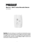
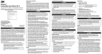
MACURCO GAS DETECTORS
CM-S1 INSTALLATION AND
OPERATION INSTRUCTIONS
GENERAL INFORMATION
The CM-S1 is a low voltage (12-24 VDC) all electronic detector of Carbon Monoxide (CO). The CM–S1 is designed for connection to UL Listed
alarm control panels (Fire or Fire/Burglar or Critical Process Management Equipment). NOTE: Any time the words “Control Panel” or “Alarm
Panel” or “Alarm Control Panel” are used in these instructions, what is meant is a UL Listed Fire or Fire/Burglar or Critical Process Management
Equipment. Alarm control panels that work on 12 or 24 VDC can provide battery backup to the CM-S1 detectors. This carbon monoxide detector is
designed to detect CO gas from ANY source of combustion. It is NOT designed to detect smoke, fire or any other gas.
LOCATION
There are two usual sources of CO in homes -- defective heat sources (furnaces or wood burning stoves) and automobiles running in adjoining
garages. The CM-S1 can provide protection from these sources, as well as any other sources of CO.
For best protection, mount a CM-S1 in the hallway near each bedroom area. In addition, another CM-S1 may be mounted just inside the door from
the adjoining garage. Consider placing another detector in a bedroom that is adjacent to a furnace room.
Do NOT mount the unit in the garage. Do NOT mount the CM-S1 where the normal ambient temperature is below 40° F (4.4° C) or exceeds 100° F
(37.8° C), or within 5 feet (1.5 meters) of a cooking appliance.
SPECIFICATIONS
Voltage: 12-24 VDC
Size: 3 1/8” x 5 1/8” x 1 ½”
Shipping Weight (each): One pound
Alarm Relay: SPDT, 1 Amp, 60 VDC, 60 VA
Alarm Setting: Per UL 2034
Color: White
Current (standby/alarm @ 12-24V): 20mA/40mA (250 mA peak for 14ms/sec)
Power (standby/alarm @ 12V): ¼ Watt / ½ Watt
Power (standby/alarm @ 24V): ½ Watt / 1 Watt
Operating Temperature Range: 32° to 120° F
Buzzer Rating: 85 dBA at 10 Feet
INSTALLATION
See wiring diagram on page 4 for information on connections of the CM-S1. Macurco recommends a minimum of 22 AWG wire for runs up to 200
ft., and 18 AWG wire for longer runs.
Mount the CM-S1 at the height that people breath: 4 to 5 feet (1.2 to 1.5 meters) above the floor. The unit can be placed vertically or horizontally on
a wall, so the information on the front of the CM-S1 can be read in a normal manner. The word UP and a directional arrow on the internal cover
indicate the correct mounting orientation of the detector.
A rear housing enclosure is included with the CM-S1 faceplate. This enclosure configuration allows the unit to mount-flush on a wall. Wiring is
routed through an access area on the base of the rear housing. A thin mid-plate enclosure component is also supplied with the CM-S1. This midplate component is used to mount the CM-S1 on a 2 x 4 single-gang, or “handy” electrical box, provided by the installer. The CM-S1’s faceplate
component (with the detector attached) is then mounted on the mid-plate component. Electrical connections to the CM-S1 are made via the supplied
five-conductor pigtail cable. The pigtail cable is first connected to the control panel wiring by means of wire nuts (refer to wiring diagram on page 4
for proper pigtail wiring). The pigtail cable’s connector then snaps into the mating connector on the back of the CM-S1 PCA, allowing easy
installation and replacement of it. For proper detector operation, ensure that the CM-S1 is connected to a continuous source of power (not controlled
by a wall switch). The CM-S1 power consumption figures represent worst-case conditions and will vary as the applied DC voltage varies.
The alarm relay of the CM-S1 is a dry contact and rated at 1 Amp, 60 VDC, 60 VA. It is not suitable for fan control use. When connecting the units
to remote buzzers or other devices (all buzzers or "other devices" must be UL approved), make sure that the load does not exceed the relay’s rating.
External buzzers must be capable of generating a sound output greater than 85 dBA at 10 ft.
Document #679-800-001
Page 1 of 4
Rev. 1.1, Jan 9, 2006
OPERATING INSTRUCTIONS
When the detector is first powered, the status light will alternate between RED and GREEN as the unit performs a 2-1/2 minute warm-up cycle and
self-test procedure. The buzzer on the CM-S1 will cycle twice, emitting its characteristic 4-chirp tone. At the end of this 2-1/2 minute cycle, the
status light will turn GREEN to indicate normal operation and safe air. The alarm relay is not energized during the 2-1/2 minute warm-up cycle.
The CM-S1 continuously monitors the air. If the CM-S1 measures levels of CO greater than the danger level, the RED light will turn on, the Alarm
Relay will switch to actuate the alarm circuits in the control panel, and the buzzer on CM-S1 units will sound. The computer in the CM-S1 is
programmed to alarm if the danger levels of carbon monoxide are exceeded, which are time and concentration-related. The alarm points are: 70 ppm
of CO after 60 to 240 minutes, 150 ppm of CO after 10 to 50 minutes, and 400 ppm of CO after 4 to 15 minutes, in accordance with the provisions of
UL Standard 2034.
WHEN AN ALARM OCCURS (INSTALLER NOTE: It is recommended the following information below be posted near the control/alarm panel
or a copy provided to the customer.)
!
1
2
3
4
WARNING: Actuation of your CO alarm indicates the presence of carbon monoxide
(CO) which can KILL YOU. If alarm signal sounds:
Operate the reset/silence button;
Call your emergency services (____________________) [fire department or 911];
Immediately move to fresh air - outdoors or by an open door/window. DO A HEAD COUNT TO CHECK THAT ALL
PERSONS ARE ACCOUNTED FOR. DO NOT RE-ENTER PREMISES NOR MOVE AWAY FROM THE OPEN
DOOR/WINDOW UNTIL THE EMERGENCY SERVICES RESPONDERS HAVE ARRIVED, THE PREMISES HAS BEEN
AIRED OUT, AND THE ALARM REMAINS IN ITS NORMAL CONDITION.
After following steps 1 - 3, if your alarm reactivates within a 24-hour period, repeat steps 1 - 3 and call a qualified
technician (____________________) to investigate for sources of CO from fuel burning equipment and appliances,
and inspect for proper operation of this equipment. If problems are identified during this inspection, have the
equipment serviced immediately. Note: Any combustion equipment not inspected by the technician, consult the
manufacturers' instructions or contact the manufacturer directly for more information about CO safety and the
equipment. Make sure that motor vehicles are not, and have not been operating in an attached garage or adjacent to
the residence.
CAUTION: This detector will only indicate the presence of carbon monoxide gas at the sensor. Carbon monoxide gas may be present in other areas.
Accommodation spaces should be well ventilated when household cleaning supplies or similar contaminants are used.
WARNING: This product is intended for use in ordinary indoor locations of family living units and office workspaces. The CM-S1 is not designed
to measure compliance with Occupational Safety and Health Administration (OSHA) commercial or industrial standards.
WARNING: Individuals with medical problems may consider using warning devices that provide audible and visual signals for carbon
monoxide concentrations below 30 ppm.
The following symptoms are related to CARBON MONOXIDE POISONING and should be discussed with ALL members of the household:
•
•
•
Mild exposure: Slight headache, nausea, vomiting, fatigue (often described as “Flu-like” symptoms).
Medium Exposure: Severe throbbing headache, drowsiness, confusion, fast heart rate.
Extreme Exposure: Unconsciousness, convulsions, cardio respiratory failure, and death.
Many cases of reported CARBON MONOXIDE POISONING indicate that while victims are aware they are not well, they become so disoriented
they are unable to save themselves by either exiting the building or calling for assistance. Young children and household pets may be the first
affected.
NOTICE: Transient CO situations can occur:
1.) Excessive spillage or reverse venting of fuel burning appliances caused by outdoor ambient conditions, such as:
a. Wind direction and/or velocity, including high gusts of wind. Heavy air in the vent pipes (cold/humid air with extended
periods between cycles).
b. Negative pressure differential resulting from the use of exhaust fans.
c. Simultaneous operation of several fuel-burning appliances competing for limited internal air.
d. Vent pipe connections vibrating loose from clothes dryers, furnaces, or water heaters.
e. Obstruction in or unconventional vent pipe designs, which can amplify the above situations.
2.) Extended operation of unvented fuel burning devices (range, oven, fireplace, etc.).
3.) Temperature inversions, which can trap, exhaust gasses near the ground.
4.) Car idling in an open or closed attached garage, or near a home.
The CM-S1 will automatically reset once the air clears.
Document #679-800-001
Page 2 of 4
Rev. 1.1, Jan 9, 2006
RESET/SILENCE SWITCH
The switch on the front of the CM-S1 labeled “TEST/RESET,” performs three functions.
1.) A short press of switch, less than 5 seconds long, will place the unit into self test mode with no alarm relay activation. The status light will turn
red for 5 seconds and then it will alternate slowly between green and amber while the self-test executes. The controlling software simulates a 3000
ppm CO environment and causes the unit to alarm after approximately one minute has elapsed. When this happens, the status light turns red and the
buzzer will sound two complete alarm cycles. The unit will then return to normal operation.
2.) A long press of switch, about 6 seconds long, will place the unit into self-test mode with alarm relay activation. Pressing and holding the switch
will cause the status light to turn red for 5 seconds and then switch to solid amber. The alarm relay will then be activated and the switch can be
released. After about 5 seconds, the alarm relay will turn off and the status light will alternate slowly between green and amber while the self test
executes The controlling software simulates a 3000 ppm CO environment and causes the unit to alarm after approximately one minute has elapsed.
When this happens, the status light turns red and the buzzer will sound two complete alarm cycles. The unit will then return to normal operation.
3.) If the CM-S1 is in an alarm condition due to the detection of carbon monoxide, one push of the switch will cause the alarm buzzer to mute for
five minutes. After the five-minute period, if CO is still present, the status light will again switch to RED, the alarm relay will close and the buzzer
will sound.
TROUBLE INDICATOR
The CM-S1’s status LED is normally illuminated with a green color. To indicate a “trouble” condition, the CM-S1 status LED will flash
AMBER and the CM-S1 buzzer will emit a short "chirp" every 50 seconds. See ERRORS below. The CM-S1 computer continuously monitors
various detector parameters. Failure of the CM-S1’s internal power supply, or a lack of power to the detector will result in the status light
remaining OFF (not illuminated). In this case, the most common cause of detector trouble would be a break in the wiring between the control
panel and the CM-S1. The CM-S1 does NOT provide a trouble signal to the alarm panel.
ERRORS
The computer in the CM-S1 continuously monitors various operating parameters. If a problem is found, the unit will switch to Trouble mode. See
TROUBLE INDICATOR above. To reset the unit for normal operation, press the TEST/RESET switch, or remove power to the unit, wait a few
seconds, then re-apply unit power. If this problem persists, your detector requires repair; contact the alarm panel installer or Macurco Tech Support
for advice. If repair is required, return the unit to manufacturer to comply with warranty.
MAINTENANCE
The CM-S1 should be tested monthly by pushing the TEST/RESET switch; see TEST/RESET switch, above. At the same time, the CM-S1 should be
cleaned using the soft brush attachment of your vacuum cleaner. The CM-S1 should be tested after cleaning to ensure the unit is operating normally.
There are no field calibration procedures for this unit.
SENSOR POISONS
The gas sensor in the detector is designed with extreme sensitivity to the environment. As a result, the CO sensor may be damaged if it is exposed to
a direct spray from aerosols such as paints, silicone vapors, etc., or to a high density of corrosive gases such as hydrogen sulfide or sulfur dioxide for
an extended period of time. The sensor may react to chemicals such as ammoniated cleaning agents, volatile solvents and hydrogen gas. In sufficient
concentration, these chemicals may cause a false alarm.
LIMITED WARRANTY
Aerion Technologies Inc. (ATI), manufacturer of Macurco products, warrants the CM-S1 gas detector will be free from defective materials and
workmanship for a period of five (5) years from date of manufacture (stamped on the unit), provided it is maintained and used in accordance with
ATI’s instructions and/or recommendations. If any component becomes defective during the warranty period, it will be replaced or repaired free of
charge, if the unit is returned in accordance with the instructions below. This warranty does not apply to units that have been altered or had repair
attempted, or that have been subjected to abuse, accidental or otherwise. The above warranty is in lieu of all other express warranties, obligations or
liabilities. THE IMPLIED WARRANTIES OF MERCHANTABILITY AND FITNESS FOR PARTICULAR PURPOSE ARE LIMITED TO A
PERIOD OF FINE (5) YEARS FROM THE PURCHASE DATE. ATI shall not be liable for any incidental or consequential damages for breach of
this or any other warranty, express or implied, arising out of or related to the use of said gas detector. Manufacturer or its agent's liability shall be
limited to replacement or repair as set forth above. Buyer’s sole and exclusive remedies are return of the goods and repayment of the price, or repair
and replacement of non-conforming goods or parts. (The Uniform Commercial Code applicable in the State of Colorado shall govern.)
RETURN INSTRUCTIONS
Call (303) 781-4062 for a Return Authorization number. After receiving a Return Authorization number, carefully pack the detector with a written
description of the nature of the return. Send the unit to the following address: Aerion Technologies Inc., Attn: Macurco Repair RA#_______,
6555 S. Kenton St., Ste. 304, Centennial, CO 80111.
Document #679-800-001
Page 3 of 4
Rev. 1.1, Jan 9, 2006
WIRING DIAGRAMS
ENSURE POWER IS OFF WHEN CONNECTING THE PIGTAIL CABLE TO THE CM-S1
!
TYPICAL CONNECTION OF TWO CM-S1's TO AN ALARM CONTROL PANEL
CM-S1
N.O. initiating
circuit
Battery-backed 12 or 24
VDC Power Supply. Fuse
or current limit at 0.5 A for
each CM-S1
SPDT
Alarm
relay
GND
12/24V
N.O. VIO
N.C. BLU
COM YEL
BLK
RED
12/24V GND
CM-S1
SPDT
Alarm
relay
GND
12/24V
N.O. VIO
N.C. BLU
COM YEL
BLK
RED
E.O.L.R.
UL Listed Alarm Control Panel
1.
The CM-S1 is for use with UL Listed Alarm Control Panels (Fire or Fire/Burglar type or Critical Process Management Equipment)
that have 12 to 24 VDC alarm initiating circuits.
2.
The Alarm Control Panel (Fire or Fire/Burglar type or Critical Process Management Equipment) must be dedicated to CO detection or
have alarm devices that provide a distinctive alarm for carbon monoxide detection. Do not connect the CM-S1 to Fire Alarm Circuits.
3.
The CM-S1 is intended for installation in buildings in non-hazardous locations such as residences, retail stores, office buildings and
institutional buildings.
4.
The CM-S1 is NOT intended for use in industrial applications such as refineries, chemical plants, etc. The CM-S1 is NOT intended
for use in parking garages, as the controller for exhaust systems.
5.
LOCATION: Place the unit at a level where people breathe: about 5 feet (1.5 meters) above the floor. Mount the CM-S1 in a vertical
position on a wall or column. Do NOT mount the CM-S1 in a corner.
6.
SPACING: Use the same spacing as for smoke detectors – 30 foot (9 meters) centers, 900 sq. feet (83 sq. meters) per detector.
7.
INSTALLATION: See page 1.
8.
The alarm control panel zone inputs must be terminated with end of line resistors (E.O.L.R.), which are provided with the panel.
9.
When using the CM-S1 with normally closed initiating circuits, use the "N.C." and "COM" alarm relay connections.
The CM-S1 has not been evaluated as a stand-alone unit by U.L.
CM-S1 CONTROLLING A REMOTE ALARM
CM-S1
SPDT
Alarm
relay
GND
12/24V
N.O. VIO
N.C. BLU
COM YEL
BLK
RED
Alarm Relay: SPDT,
1.0 Amps., 60VDC, 60 VA
dry contacts, no polarity
UL Listed Class 2
Power Source:
12-24 VDC, 1 VA
CM-S1
SPDT
Alarm
relay
GND
12/24V
UL
LISTED
12VDC
ALARM
N.O. VIO
N.C. BLU
COM YEL
BLK
RED
UL LISTED
12VDC
POWER SUPPLY
Document #679-800-001
Page 4 of 4
POWER
Rev. 1.1, Jan 9, 2006