1
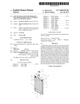
IPRO 310: Conversion of a Commercial-Grade Riding Lawnmower to Hydrogen Fuel Advisors: Dr. Said Al-Hallaj and Dr. Francisco Ruiz Team Leader: Steffany Evanoff Teaching Assistant: Kristofer Kiszynski Conversion Team Daniel Taulbee - Leader Preeti Abraham Steffany Evanoff Yewon Gim Lab Safety Team Joel Fenner – Leader Jason Neale Minsuk Jung Minjoong Kim Chungyun Kim Testing Team Nate Gates - Leader Nathan Knopp Melissa Lemons Jim Nihei Karen Sedacki Frank Costanzo Brett Schlimm IPRO Deliverables Groups Mid-Term Report: Preeti Abraham, Jim Nihei, Karen Sedacki Final Report: Melissa Lemons, Nate Gates, Nathan Knopp, Joel Fenner Poster: Chungyun Kim, Minjoong Kim, Frank Costanzo Presentation: Yewon Gim, Dan Taulbee, Minsuk Jung Recorder of Minutes: Jason Neale 2 Table of Contents Project Introduction………………………………………………………….. Pg. 3 Project Objectives……………………………………………………………. Pg. 3 Background Information……………………………………………………... Pg. 3 - 5 Research Methodology……………………………………………………….. Pg. 5 Assignments…………………………………………………………………... Pg. 5 – 6 Obstacles……………………………………………………………………… Pg. 7 – 8 Results………………………………………………………………………… Pg. 9 – 14 References and Acknowledgments…………………………………………… Pg. 15 - 16 Appendix 1……………………………………………………………………. Pg. 16 - 18 Appendix 2……………………………………………………………………. Pg. 19 – 21 Appendix 3……………………………………………………………………. Pg. 22 - 23 Appendix 4……………………………………………………………………. Pg. 24 - 28 Appendix 5……………………………………………………………………. Pg. 29 - 34 3 Project Introduction: IPRO 310 is responsible for researching the safe and efficient conversion of a gasoline-powered riding lawnmower to run on gaseous hydrogen. A lawnmower emits 10-12 times as many emissions as does a typical automobile. Due to the Bush administration’s push for alternative and more efficient fuel sources and the unacceptable lawnmower emissions, the Chicago Parks District (CPD) contacted the IPRO office two semesters ago and challenged them with the task of investigating a more environmentally friendly fuel option – gaseous hydrogen – and its possible application to lawnmowers. Project Objectives: The objective of this project was to asses the feasibility of converting a lawnmower to hydrogen fuel. This involved the revision of the previous semester’s conversion plan, proposal of a new, more realistic hydrogen tank mounting system, and preparation of the laboratory for testing. Background Information: Contributions from the last IPRO team included the performance of benchmark tests to verify the engine specifications provided by John Deere, formulation of a conversion methodology, and proposal of a mounting system for the hydrogen tanks on the lawnmower. The benchmark testing that took place last semester proved to be vague. The results of the testing attempt to show the gasoline consumption at different throttle settings. A graph of the findings is below. Gasoline Consumption 40 35 Min/Litre 30 25 20 15 10 5 0 Throttle 1 Throttle 2 Throttle 3 Blades Figure 1- Previous Semester Benchmark Testing Two problems arise after reviewing Figure 1. First of all, the throttle positions have no standard reference. Therefore, the tests cannot be duplicated. Secondly, the fuel consumption does not 4 supply an adequate description of engine performance. The engine needed to be assessed in such a way that an optimum efficiency is found. This is done by creating an engine fuel map. An example of a fuel map is shown in Figure 2. Figure 2- Example of an Engine Fuel Map In a fuel map, torque vs RPM’s and Power vs RPM’s is obtained. After various tests, a point along the graph develops which appears to be a point of intersection. At this point, the engine’s maximum efficiency is obtained. This point is the point where the comparison of the performance with each fuel will be made. The purpose of the Testing Team was to obtain these engine maps. A key component of this project was the research into converting the lawnmower engine to run on hydrogen fuel, and the eventual conversion of the engine. This required extensive thermodynamic modeling of the engine, as well as research into the feasibility and design of a hydrogen engine. Hydrogen powered engines have been produced in the past; however, no information is available on the conversion of a lawnmower. During the Fall 2005 semester, work was started on calculating the power output of the lawnmower, as well as the cost to benefit ratio for both gasoline and hydrogen fuel. A mounting system for the hydrogen tanks onto the lawnmower was also proposed. This mounting system is included in Figure 3. 5 Figure 3. Previously Proposed Mounting System Research Methodology: From the Project Plan (included in Appendix 1) created at the beginning of the semester, the objectives were to: Finish benchmark testing on the lawnmower Further research the safe storing and usage of hydrogen Develop guidelines to create and maintain a safe laboratory area Investigate avenues to decrease the overall conversion cost Perform the engine conversion Create a conversion manual as well as a lab safety manual The methods used to complete these objectives included extensive review of existing literature on the subject of hydrogen conversion and safety and investigation in the lab. Also, the expertise of professors and faculty was utilized for consulting purposes, especially regarding the testing and conversion aspects of the project. After assessing the state of the laboratory at the beginning of the semester, these objectives were somewhat altered, and another objective of repairing the laboratory equipment was added to the testing team objectives, resulting in the completion of the other objectives becoming questionable. Assignments: In order to complete the proposed objectives, the IPRO team was reorganized into three subteams, each charged with a unique aspect of the project. These sub-teams were the conversion team, the lab safety team, and the testing team. The conversion team was assigned the task of creating a methodology for converting the gasoline engine to hydrogen. The lab safety team was entrusted with the responsibility of maintaining a safe environment in the testing lab, as well as ensuring that the final converted lawn mower would be safe for use by the common consumer. This team was also designated the task of writing a hydrogen safety manual that could be referred to by future IPRO groups, as well as a training presentation. The testing team was 6 delegated the task of performing benchmark testing on the engine, converting the engine using the conversion team’s created procedure, and re-testing the engine after conversion. A more detailed description of each groups’ responsibilities is included below. Conversion Sub-Team Calculate the power output and compare the cost to benefit ratio for each type of fuel Research, select, and purchase the components necessary for the conversion process Develop detailed conversion guidelines that comply with the safety standards proposed by the lab safety sub-team Convert the engine to use gaseous hydrogen as its fuel Establish a testing and tuning procedure Integrate the converted engine with the lawnmower Design a safe and convenient tank mounting system Lab Safety Sub-Team Maintain a safe environment in the testing lab Research safety requirements for hydrogen use in motor vehicles Develop a thorough and complete safety code for hydrogen use both in the testing lab and on the lawnmower. Work closely with Testing and Conversion sub-teams to help implement safety codes and protocols in their work Install hydrogen detection and safety equipment in the testing lab Testing Sub-Team Remove the engine from the lawnmower and get it into the testing laboratory Learn how to operate and repair the DYNOmite 2000 Perform engine tests using the dynamometer to obtain a power curve and other useful parameters that will be compared to that of the converted engine Perform gas analyzer test to compare before- and after-conversion emissions Analyze the results obtained from testing and compare the results from the preconversion testing to those obtained after the conversion Throughout the semester, each sub-team was also responsible for keeping the entire team up to date on its progress through reports and presentations. Obstacles: Conversion Sub-Team One of the major obstacles encountered by the conversion sub-team was a lack of familiarity with the Otto Cycle. This resulted is several errors made during the early development of the thermodynamic models, such as impossibly high calculated temperatures inside the engine 7 during combustion. However, these errors were corrected with the help of Prof. Ruiz. Also, as the power loss factors are empirical and not theoretical in nature, it was difficult to find a reliable source for them. While researching conversion procedures, several obstacles were encountered. Not many companies make high-quality alternative fuel products, so choices were limited. Detailed information and price quotes were not readily available, and the companies had to be contacted by telephone during regular business hours. Alternative spark plugs and piston rings were difficult to find as they are not made for small engines. Locating a hydrogen supplier in the Chicagoland area, who meets the team’s requirements, was also very challenging. The technical specifications for the A360W hydrogen tanks provided by Luxfer Composites were not very clear about the tanks’ threading, so a technical representative at Luxfer Composites was contacted regarding this issue. This led to delays in placing the purchase order for the tanks with Luxfer Composites. It has been difficult to devise a tank mounting system. With a heavy-duty 25 hp motor, it is necessary to carry a substantial amount of compressed hydrogen gas to allow for lengthy runtimes between refilling. Therefore, the tanks ordered for the conversion are a bit bulky. The current layout of the lawnmower leaves little room for additional components. Even removing the old gas tank will not create sufficient additional room. This issue will need to be explored more fully, especially after the delivery of the tanks from Luxfer Composites. Connecting one component of the fuel delivery system to another is proving to be quite a difficult task. It is not easy to determine the tubing and adapter types needed to connect these parts together in a safe and reliable manner. Every company that the team spoke with was knowledgeable in the safety guidelines and best methods for delivering propane. However, the properties of the H2 molecule are much different from those of the propane molecule. Rubber hosing, which can be used for propane, was therefore not an option for this project. Lab Safety Sub-Team: Strict requirements for hydrogen use in confined spaces (from the codes reviewed) would have required major modifications to the testing lab if a large hydrogen quantity was to be kept there. As an alternative, by carefully controlling the amount of hydrogen stored in the lab, most of the hazardous issues that the lab modifications were meant to address can be avoided, thereby making it possible to safely use hydrogen in the lab without major modifications. Permanent hydrogen tanks, as opposed to rented tanks, pose a greater safety hazard as they must be refilled and inspected. These will likely be a necessity for the finished hydrogen lawnmower, as the gas supplier only offers one pressure-vessel size for rental. This issue is currently unresolved. With the present constraint on the quantity of hydrogen which can be stored in the lab, the theoretical run-time of the engine on a single charge of hydrogen is on the order of 5 minutes. This may be too short a time to obtain useful test data from the dynamometer in a single run. Should this constraint be a problem, it may be possible to move the equipment to another location (temporarily) where a larger quantity of hydrogen can be used. Safety codes 8 pertinent to the use of hydrogen specifically on motor vehicles have been somewhat vague thus far. The codes reviewed do provide a wealth of information about hydrogen safety in any environment, but it would be helpful to have more definitive information about the motor vehicle context. Testing Sub-Team The dynamometer was the most important and necessary piece of equipment to be used by the testing team. This instrument was designed to perform engine tests, collect experimental data from these tests, and input this data to a computer. However, the dynamometer was missing many necessary parts, and some parts had been destroyed. The torque arm probe, which allows the computer to communicate with the load cell, was completely destroyed. Also, the tachometer’s wires had been severed and some of its parts were missing. The load cell dial on the control panel, which was designed to allow the operator of the test to change the load being applied to the engine, was broken and would not move when attempts were made to turn it. Also, the piping system which would deliver the necessary water to apply the load was not working correctly and was leaking. It was discovered that the dynamometer had no probe for measuring the flow rate of air into the engine. An instrument designed to measure the flow rate had to be created by the testing team members. The testing team also experienced difficulty in determining how to start the engine while on the dynamometer. The starter system had not been removed along with the engine, so a starter system had to be designed in the laboratory. This was such a daunting task because the group members lacked experience with electrical engineering. Once the engine had been started on the dynamometer, it was discovered that the throttle linkage, which would allow the tester to control the engine’s throttle, was also not operational. A new throttle linkage had to be designed to replace this defective part. Results: Each sub-team worked diligently throughout the semester to reach their objectives and ultimately the final goal. Listed below are each of the sub-teams’ accomplishments. Conversion Sub-Team The conversion sub-team created thermodynamic models for the Kawasaki FH721D engine used by the John Deere lawnmower for both gasoline and hydrogen. These were developed using the Otto cycle (see Figure 1), which is the idealized internal combustion engine cycle, and taking into account power losses due to friction and appropriate heat losses. 9 Figure 4: The Otto Cycle To find the value of the ideal net work expected from the lawnmower engine, the formula for the thermal efficiency, th , of the Otto cycle, expressed by Equation 1, is used. th 1 1 r k1 Equation 1. Thermal Efficiency of the Otto Cycle In Equation 1, r is the compression ratio, which is the ratio of the greatest displacement to the least displacement in the cylinder, and k is the ratio of constant pressure specific heat of the airfuel mixture to the constant volume specific heat of the same mixture. However, thermal efficiency is also defined in a more general manner by Equation 2. th W net Qin Equation 2. General Form of Thermal Efficiency In Equation 2, W net is the net work output and Qin is the heat added to the cycle due to combustion. Combining Equations 1 and 2, an expression for net work output is obtained. Qin can be from the heat of combustion of the fuel and the quantity of the fuel in the cylinder calculated during combustion.. Thus, a value of net work output is obtained for both the gasoline and hydrogen powered engines. Net power output values are then calculated using the engine rpm (revolutions per minute) value at the peak power output as specified on the engine data sheet. 10 In order to calculate the real power outputs, empirical friction and heat loss factors found in reference materials from similar engines are used. The real values of the power outputs are 26.6 hp for the gasoline engine and 18.275 hp for the hydrogen engine. The predicted power output for the gasoline engine is close to 25 hp provided by Kawasaki specifications. This confirms the validity of the sub-team’s thermodynamic model. Despite hydrogen having a higher heat of combustion per unit mass, the hydrogen engine will have a lower power output than the gasoline engine because gasoline is much denser than hydrogen. After constructing the thermodynamic models, the conversion sub-team began researching engine conversion procedures that would result in a safe hydrogen engine that was approximately as powerful as the current gasoline engine. Some of the issues that needed to be addressed were hydrogen embrittlement, gaseous fuel delivery, improved cooling, abnormal combustion, and the management of combustion products. Hydrogen needs to be stored in special tanks, because it causes embrittlement in ordinary steel tanks or the gasoline tanks currently on the lawnmower. Hydrogen embrittlement occurs when hydrogen molecules, which are much smaller than the gasoline hydro-carbon molecule, are absorbed by surrounding material. Once the hydrogen enters metal crystal lattices, it reduces the ductility and load-bearing capacity of the material, making it susceptible to cracking and brittle failures at low stresses such as the normal vibrations of an operating lawnmower. Also, the hydrogen can eventually migrate all the way through surrounding metal into the air. The materials that can be used in contact with hydrogen safely are 316 and 304 Stainless Steels, aluminum, and composite materials. Aluminum is more resistant to embrittlement than the stainless steels, and it costs less and is stronger than composites. However, composites are safer and lighter than aluminum. Therefore the conversion sub-team decided on composite tanks for the actual converted lawnmower model. One of the largest problems associated with hydrogen-fuel engines is pre-ignition or backfire. This is when the fuel ignites before it is supposed to in the combustion cycle. The carburetor system used to regulate the air-fuel mixture needed to be adapted for use with a gaseous fuel. An adapter and various components between the hydrogen tanks and the carburetor are necessary. The new system also adds the hydrogen to the air closer to the cylinder to prevent backfire thus making the old fuel intake port useless. Also, as larger amounts of heat would be produced during hydrogen combustion, an improved cooling system would be helpful in preventing overheating, a precursor to pre-ignition. Another way of preventing backfire would be to use stainless-steel-tipped spark plugs instead of the platinum-tipped spark plugs that are currently used. Because hydrogen can explode at a variety of concentrations and even with small heat sources, a stainless-steel-tipped spark plug that will dissipate heat faster than a normal platinumtipped spark plug, preventing unwanted ignition in the cylinder. Furthermore, piston rings with a better seal between the piston wall and the cylinder would be needed to prevent leakage of the excess water produced during combustion into the oil pan and to prevent oil from seeping into the top of the cylinder, another condition encouraging pre-ignition. 11 After considering many options, the conversion sub-team decided on a tank mounting system that will consist of two side mounted tanks. The team had originally planned on mounting both tanks in the front of the mower near the feet of the operator, but the 10” diameter of the tanks would not allow for a good fit. This newly proposed mounting system is included in Figure 5. Figure 5. Hydrogen Tank Mounting System Lab Safety Sub-Team: The principal goal of the lab safety sub-team was to obtain information about the safe use of hydrogen in the context of a laboratory environment and in the more practical context of a motor vehicle. The lab safety sub-team has thoroughly reviewed five separate codes for hydrogen and compressed fuel gas safety: one from the National Aeronautics and Space Administration (NASA), one from the National Fire Protection Association (NFPA), one from the Occupational Safety and Health Administration (OSHA), and two from the International Code Council (ICC). Using the information from those five codes, a lab safety manual was created to inform future teams of the safety requirements directly applied to the use of gaseous hydrogen in the context of the conversion project. This manual is included in Appendix 5 of this report. Necessary safety equipment for the lab to detect hydrogen leakage and warn personnel in the event of a leak have been identified. The maximum safe quantity of hydrogen that may be kept in the lab at any given time to comply with safety codes has been determined. A training presentation, intended to familiarize any personnel working in the lab with the basic elements of hydrogen safety was prepared. As far as the specifics of hydrogen safety in the laboratory are concerned, the NASA and OSHA documents have proven most applicable. The codes specify strict restrictions on the volumetric concentration of hydrogen in the air (as hydrogen is likely to leak at some slight rate). For general purposes, no more than a 1% concentration of hydrogen by volume is permissible, this value being ¼ of the concentration required to pose a combustion hazard. To comply with this 12 restriction, members of the lab safety sub-team took measurements of the dimensions of the room and calculated the maximum safe quantity of hydrogen which, if leaked, would cause that 1% concentration to develop. This value was calculated as 0.41 pounds of hydrogen. Therefore, for the purposes of engine testing in the laboratory, no more than 0.41 pounds of hydrogen shall be allowed in the lab at any given time to prevent even the possibility of exceeding the 1% volumetric concentration in the event that all the hydrogen is inadvertently leaked. As a further safety concern in the lab, nearly all the codes specify the use of a hydrogen detector to warn personnel if the hydrogen concentration should reach the 1% volumetric threshold. The detector must give audible and visible warning so personnel may perform a shutdown of the hydrogen equipment and then evacuate the lab until the concentration drops to safer levels. The team has selected a detector and associated warning lights and alarms to be installed in the lab to comply with this specification. Some of the work of the lab safety sub-team has bearing on the work of the conversion team. This is very much the case as far as the issues of hydrogen embrittlement and diffusion are concerned. The various codes (particularly NASA and ICC) discuss the effects of hydrogen on metals. In general, the codes recommend the use of stainless steels or aluminum alloys as these substances tend to show the least effects of hydrogen embrittlement. The NFPA compressed gas codes, however, suggest that certain DOT certified grades of ordinary chromium-molybdenum steels are acceptable for pressure vessels, provided that those vessels are produced in compliance with DOT specifications. As an additional safety concern, the NASA codes point out that plastic deformations in metals tend to serve as an initiation mechanism for accelerated hydrogen embrittlement. For example, if a pressure vessel or a hydrogen-carrying component (pipe, pressure regulator, etc.) becomes dented or malformed in some way, hydrogen embrittlement is likely to become accelerated at the site of that damage. The insidious part of the problem is that the embrittlement will occur at the interface between hydrogen and metal (i.e., on the inside), making visual detection of crack development nearly impossible until a crack has propagated to the outside of the component. This means that any component damaged in use should be taken out of service and replaced because, if left in service, it may fail suddenly after a long period of time. While it is the goal of the lab safety sub-team to prevent any sort of hydrogen accident, the issue of a hydrogen fire should be considered. In the event that a hydrogen leak should develop and ultimately begin to burn in a controlled manner (like a gas torch or Bunsen burner), the safety codes insist that the utmost priority is to disable the hydrogen supply. In our case, this should simply entail closing off the supply valve from a hydrogen tank. Furthermore, while it may seem counter-intuitive, the safety codes indicate that it is unsafe to extinguish such a hydrogen fire if the hydrogen supply has not been disabled. The reasoning behind this is that a controlled fire is, in a certain sense, stable. If the hydrogen fire should be extinguished with the hydrogen supply still active, hydrogen gas may simply begin to concentrate in a cloud. If accidentally ignited, that hydrogen cloud may pose an explosion hazard, whereas the prior hydrogen flame posed no such explosion hazard. 13 Information regarding the safe use of hydrogen on motor vehicles is more vague. The codes are quite clear about the high diffusion rates of hydrogen in air. Hydrogen is lighter than air (as opposed to other fuel gases like propane or methane) and naturally diffuses upward. Hydrogen also naturally diffuses horizontally at high rates. These two factors suggest that hydrogen use in motor vehicles is somewhat safer (computer modeling presented in the NFPA codes confirms this) than other fuel gases as it is less likely to become concentrated in the event of a leak. Testing Sub-Team: The current accomplishments of the testing team subgroup include removal of the engine from the John Deere 757 ® Commercial Lawn Mower (see Figures 1 and 2 in Appendix 2), mounting the engine in order to make important measurements utilizing the DYNO-MITE 2000, and starting the engine. Removal of the Kawasaki type FH271B 25 hp engine, involved the simple technique of removing each bolt that connected the engine to the lawnmower, as well as disconnecting each belt on the engine that was connected to the lawnmower. Mounting the engine involved simply placing four bolts through both the engine stand and the engine mount that is on the DYNO-MITE 2000. The load cell was not securely in place on the Dyno, so braces were created to keep it securely in place. These braces were created not only for safety, but to ensure accuracy during testing as well. Starting the engine was a process solved by making the proper electrical connections with the engine and providing sufficient fuel to the engine. The proper connections for starting the engine were made after carefully analyzing the schematics of all the electrical leads (see Figure 3 in Appendix 2). As a result, the engine can be started using a set of switches. This project has required a large focus on repairing the testing equipment. First the load servo, a valve that allows water to flow through the Dyno to apply the load on the engine, was in need of repair. So, the servo was taken apart, cleaned, and a new O-Ring was added to it. Next, the torque arm had a severed wire. To fix the problem, a new connecter was bought and the torque arm was re-wired and soldered. Another problem with the testing equipment was that the throttle linkage, which allows the Dynamometer to control throttle on the engine, was not working properly. The linkage functioned properly when increasing the throttle, but when attempts were made to decrease the throttle, the linkage remained stuck in the high position. This was largely due to buckling in the cable. It was necessary that the cable remained taught to provide adequate force to return the throttle to rest. Plans were drawn up to reconstruct this linkage, which included adding restrictive copper tubing to increase the rigidity of the system and prevent buckling of the cable. The throttle now works through a series of cables which connect the throttle control to the engine throttle. The last major repair that needed to be made to the Dynamometer was the torque arm calibration. This was done by adding a known weight to the arm and then manually setting the computer to read out the correct torque. After the correct data was entered, the weight was removed and the torque arm “zeroed”. Unfortunately, this process was unsuccessful. It was determined that the strain gage on the load cell was faulty. This piece of equipment was far to complex to be repaired or replaced by the IPRO team. The load cell was sent to Land and Sea Corporation in order for the necessary repairs to be made. Repairs to the load cell dial are still in progress, preventing the team from completing a test. Two major instruments were created during the project, the first of which was a simple device which measures the flow rate of the air going into the engine. This was done using a paint drum, a manometer, and some piping. Holes of known diameter were cut out of the top of 14 the paint drum, with the hole designated for the engine air intake being significantly larger than the second hole. A manometer was mounted to the side of the drum, allowing the team to measure the pressure difference between atmosphere and the air entering the engine. Using the Bernoulli equation, a velocity for the air entering the engine was calculated. Multiplying this velocity by the area of the hole designated for the intake, the volume flow rate of the air entering the engine was determined. From this and the data from the fuel flow meter, an air-to-fuel ratio was derived. Next, a procedure was written on how to perform a fuel mapping test and thus create an engine map. This was done so that in the future, the engine map could be created very quickly. This procedure is included in Appendix 4 for future teams to reference. It was also necessary to perform a flow rate test to ensure that the water piping system would provide the necessary flow rate to apply the load. For a 25 hp engine, this necessary flow rate was 1.25 gal/min. To perform this test, an empty one gallon milk jug was filled with water while the elapsed time was measured using a stopwatch. Our piping system was able to deliver 1 gallon of water in 13 seconds, which exceeded the necessary flow rate specified by the dynamometer’s laboratory manual. References and Acknowledgments: Boles, Michael A., and Cengel, Yunus A. Thermodynamics: An Engineering Approach. New Delhi: Tata McGraw-Hill Publishing Company Limited, 2003. Francort, James. Hydrogen Internal Combustion Engine Vehicles. Idaho National Laboratory-Hydrogen Internal combustion. 26 Feb. 2006. <http://avt.inel.gov/> Guo, L.S., Li, J.D., and Lu, H.B. “A Hydrogen Injection system with solenoid valves for four-cylinder hydrogen fueled engine.” Journal of Hydrogen Energy. “Head Porting for Do-it- Yourself.” Standard Abrasives, Motor Sports Division. Inchley, William. Theory of Heat Engines. London, New York [etc.]: Longmans, Green & co., 1913. Industrial, Specialty and Medical Gases Shipped World Wide. 11 May 2004. Mittler Supplies. 10 April, 2006. <http://www.mittler.com/> International Code Council. (2003). International Fire Code [Electronic version]. International Code Council. (2003). International Fuel Gas Code [Electronic version]. Jan, Macek, Milos, Polasek, and Takats. “Hydrogen Fueled Engine – Properties of Working Cycle and Emission Potentials.” Michal Josef Božek Research Center, Czech Technical University in Prague. John Deere. Mid-Frame Z-TrakTM Mower 737 and 757 Technical Manual. Mar. 2005. 15 Land and Sea Incorporated. DYNO-MAX 2000 User’s Manual. New Hampshire: 2005. Land and Sea Incorporated. DYNOmite Owner’s Manual. New Hampshire: 2005. Maleev, V. L. Internal-Combustion Engines: Theory and Design. New York, London: McGraw-Hill Book Company, inc., 1945. National Aeronautics & Space Administration. (1997). NSS 1740.16 Safety Standard for Hydrogen and Hydrogen Systems. [Electronic version]. National Fire Protection Association. (2005). NFPA 54: National Fuel Gas Code. National Fire Protection Association. (2005). NFPA 55: Standard for the Storage, Use, and Handling of Compressed Gases & Cryogenic Fluids. Nave, C.R. The Otto Cycle. 2005. Georgia State University. 6 Feb. 2006 <http://hyperphysics.phy-astr.gsu.edu/Hbase/thermo/otto.html> Occupational Safety & Health Administration. (2004). OSHA 1910.103 Hydrogen [Electronic version]. Popplewell, W.C. An Elementary Treatise on Heat and Heat Engines : Specially Adapted for Engineers and Students of Engineering. Manchester : Technical Pub. Co., 1897. Ramachandran, S., Sapru, K., Sievers, P., and Tan, Z. “Hydrogen Internal Combustion Engine Two Wheeler with on-board Metal Hydride Storage.” Energy Conversion Devices, Inc. Riding Mowers. 2006. John Deere and Company. 5 March 2006. <http://www.deere.com/en_US/deerecom/usa_canada.html> Schroeder, Daniel V. An Introduction to Thermal Physics. Sierens, Roger. “The Development of a Hydrogen Fueled V-8 Engine.” University of Gent. Swartz, John. Technical Consultant. 15 Jan. – 30 April 2006. Taylor, Charles Fayette. The Internal-Combustion Engine in Theory and Practice. New York: Technology Press of the Massachusetts Institute of Technology and Wiley, 1960. 16 Appendix 1 17 Gannt Chart for the Semester 18 Appendix 2 Figure1. The engine removed from the John Deere Commercial Grade Lawnmower 19 Figure 2. Engine part locations from John Deere Lawn Mower manual 20 Figure 3. Electrical Schematic diagram of the John Deere Commercial Lawn Mower 21 Appendix 3 Conversion Team Equipment List Quote from Swagelok, Gas Technologies Item Part Number Quantity Union Elbow SS-600-9 1 Union Tee SS-600-3 1 Tubing SS-T6-S-049-20 20’ Flex Metal Hose SS-FM6TA6TA6-36 1 Flex Metal Hose SS-FM6TA6TA6-18 2 High-P Regulator KPR1JRF417A20010 1 Valve SS-43GS6 1 Unit Price 16.50 24.50 4.53 210.30 178.30 399.50 69.70 Amount 16.50 24.50 90.60 210.30 713.20 399.50 69.70 Quote from IMPCO Systems Item Part Number Low-P Regulator T60-G High-P Regulator HPR-3600 Lock-Off Solenoid 4004A-12V Venturi 200-1532 Load Adj. Elbow 42EA Quantity 1 1 1 1 1 Unit Price 93.23 223.88 29.83 36.13 8.65 Amount 93.23 223.88 29.83 36.13 8.65 Necessary for the actual conversion: Quote from Luxfer Composites Item Part Number 3000 PSI Tank A360W Quantity 2 Unit Price 578.00 Amount 1156.00 Subtotal: $2715.42 (plus the Cost of Hydrogen) Necessary for our purposes: Quote from Mittler Chemical Supplier Item Part Number Hydrogen Quantity 4200L Unit Price 0.30 Amount 1260.00 Subtotal: $3975.42 (including the Cost of Hydrogen) Lab Safety Team Equipment List Quote from All Electronics Corp. Item Part Number Strobe Warning Light-Red STROBE-3R Strobe Warning Light-Amber STROBE-3A Piezo Alarm SBZ-365 12V Switching Power Supply PS-1214 SPDT 30A Relay RLY-351 Relay Socket SRLY-2 SPST Momentary Toggle Switch STS-28 Quantity 1 1 2 1 2 1 1 Unit Price 8.95 8.95 3.95 12.75 2.40 2.00 2.00 Amount 8.95 8.95 7.90 12.75 4.80 2.00 2.00 22 20A AGC Fuses AGC Fuseholder FS-20 FHP-2 Quote from Aerion Technologies, Inc., Macurco. Item Part Number 12/24V Hydrogen Detector with HD-12 Low/High Relays Quote from Digi-Key. Item Economy ESD Wrist Strap Part Number 16-1021-ND 1 2 0.75 0.50 0.75 1.00 Quantity Unit Price 1 300 Amount 300 Quantity Unit Price 3 14.14 Amount 42.42 Subtotal: $391.52 Total: $4366.94 23 Appendix 4 Creation of an Engine Map Purpose The purpose of this experiment is to find the point at which an engine runs at its optimum efficiency. Equipment Engine Gas Analyzer Air Flow Measuring System Fuel Flow Measuring System Dynamometer Procedure Open the DynoMax software Enter in the engine specifications Make sure that all equipment is calibrated correctly (Load Cell, Torque Arm, Air Flow Measuring System, Fuel Flow Measuring System, Gas Analyzer) Make sure the Dyno is communicating with the computer Start the Engine While in DynoMax software: Go to Automated Test Set Up Wizard In the Automated Test Set Up Wizard, the remaining cells in the table are for your desired Air/Fuel Ratio entries. For each location that you want to test, enter a nonzero AFR # (i.e. 13.9). The AFR #’s are entered into the (fixed location) edit box near the upper left-hand corner of the table. Except for the low RPM idling cells and the Wide-Open-Throttle (rightmost) column, most cells will contain near stoicheometric (14.7 AFR) entries – for good economy. Typically the WOT cells are a bit richer (i.e. 13.0) for maximum power. In the setting time column, enter in the time in seconds that you would like to elapse between data points Cool down time specifies the number of seconds to pause (at idle) between each set of, higher load, throttle points. When using manual throttle control, the Fuel Mapping Console’s desired Throttle (load) % needle indicates that the operator should reduce the throttle in order for the engine to cool. DYNO-MAX automatically reduces your cool down time in the early part of the test, when the engine is not working as hard. 12seconds is the default entry – increase it for higher power or poorly cooled engines! RPM tolerance is a maximum percentage (of the dynamometers Scale RPM) that the actual Engine RPM may deviate from a cell’s desired test RPM. If the RPM error exceeds this amount, that test point will be skipped over. 24 TPI (MAP) channel’s Final Reading @ 100% scales the Console’s desired Throttle (load) % needle to your sensor and table column headings. The default of 100 works for most TPI sensors – because they also use a 0 – 100% scale. However, say an ECU’s tables are based on a MAP sensor scale of 0.0 – 2.0 BAR. In that case the factor should be changed to 2 (assuming the DYNOmite’s channel is correctly calibrated to match the engine’s ECU reading) and the column headings can be entered to match the ECU’s software (i.e. 0.0, 0.2, 0.4, 0.6…2.0). For reference, the actual Throttle % always displays in the small gray field near the upper left-hand corner of the table. Use Servo Throttle Control must be pressed if planning to use the DYNOmite’s optional Electronic Throttle Control to run the engine. The throttle’s feedback channel (see Configure DYNOmite Controls) calibration and formula must also be matched to the engine’s ECU readings. In Single Cell Entry Mode your desired AFR entries will live update the highlighted cell. The PC’s four Cursor Arrow Keys may be used to move the cursor during data entry. In Multiple Cell Entry Mode the Ctrl key may be held down, while clicking the mouse, to group select multiple individual cells. Similarly, the Shift key may be held down to group select multiple adjacent (in-line) cells. Shift key selections may be done vertically, horizontally, or diagonally. More than one group may be simultaneously selected for data input. Reselecting cells removes them from the group. All selected (blue highlighted) cells will simultaneously update as you change your desired AFR entry. If the PC’s four Cursor Arrow Keys are used while holding down the Ctrl or Shift key, then the additional cells (passed over) are added to the group, if you use the Arrow Keys without the Ctrl or Shift key held down only the single destination cell will remain highlighted. Running a Test Once all your desired RPM, TPI, AFR, and other settings are configured (described above), click OK for the Wizard to program the Fuel Mapping Auto Test. If the Emissions Lab – Fuel Mapping Console is not already visible, open it now. Press the Auto button to toggle into AutoTesting Mode. Assuming the engine is correctly installed and warmed up on the dynamometer, throttle the engine to match the white needle (throttle feedback %) to the magenta desired Throttle (load) % needle (of the large center gauge). Depending on your first table column’s heading value, this may only be 0% throttle. Press the Run Auto Test button to commence testing. For the duration of the test, the operator of the throttle must use it to keep the white (actual throttle/load) needle matched to the magenta (desired) needle’s position. The Console features a pair of cyan and yellow alarm lights that warn if MORE or LESS throttle is required. When the mapping is finished, Test Completed will display in the Console’s Status window. You can now save the run and/or print out the Graph's Data Points Listing (using the Fuel Mapping.gph files Fuel Map Correction Table tab to format the results). Data The air flow can be measured using the following procedure. 25 1. Set up a control volume that has an inlet of known cross sectional area that is open to the atmosphere and an exit that has an inlet of known cross sectional area that leads to the engine’s air intake. 2. Put a manometer at the inlet and the exit of the control volume. 3. Record the manometer readings at both the inlet and the exit of the control volume. 4. Calculate the mass flow rate using the equations below p gh Equation 1 p- pressure - density of the fluid in the manometer g- gravity h- height of fluid in manometer Equation 1 will get the pressure of the the air at the exit of the control volume. The pressure at the inlet should be atmospheric if the paint drum created this semester is used. From the Bernoulli Equation 2 P1 2 V P V 1 gz1 2 2 gz 2 2 2 Neglecting Changes in Height (valid because air is so small) and Assuming V (inlet velocity) is equal to zero p1 V2 p2 Equation 2 Equation 2 will get the velocity of the air that is going into the engine. . m VA Equation 3 Equation 3 gives the mass flow rate of the air going into the engine Next, the rate of fuel consumption must be measured. This may be analyzed using two different methods. The first of which involves a device on the Dynamometer, which takes readings of the amount of fuel that passes through a given control volume. If the device on the Dyno is broken, then the rate of fuel consumption can be found by: 1. Weighing the gas tank before testing. 2. Timing the test 3. Weighing the gas tank after testing. The mass flow rate of the fuel can be calculated as follows: 26 . m m2 m1 t Equation 4 In Equation 4, m2 is the mass of the gas tank after the test, m1 is the mass of the gas tank before the test, and t is the time of the test. The dynamometer will measure the following: Torque Load Rotations Per Minute of the Engine Throttle Setting (in percent) Each data reading should have a corresponding value for Torque, Load, RPM’s, and Throttle setting. To analyze the emissions, a gas analyzer is used. This is used to measure the amount of different types of gases in the emissions of the lawnmower. This device is placed at the exhaust pipe. Data Analysis When creating an engine map, the following must be found: Engine Work Output Efficiency of Engine Torque of Engine at a given time Rotations per minute of the Engine at a given time Load applied on the Engine at a given time Throttle Setting of the Engine at a given time Also, to analyze the engine more fully, we will need to calculate the air to fuel ratio. The work output of the engine can be calculated using Equation 5: . W T RPM Equation 5 . In Equation 5, W is the work output of the engine, T is the torque of the engine, and RPM is the rotations per minute of the engine. The efficiency of the engine can be calculated using Equation 6. . W . m LHV Equation 6 27 . In Equation 6, is the efficiency of the engine, m is the mass flow rate of the fuel and LHV is the Low Heating Value. According to <http://www.motorcycle.com/mo/mcnuts/rtfuel1.html>, the Low Heating value of Gasoline is 43 MJ/kg. The air to fuel ratio can be calculated using Equation 7. . A/ F mair . Equation 7 mfuel In other words, the air to fuel ratio is the mass flow rate of the air over the mass flow rate of the fuel. Creating the Map The actual creation of the map requires making a graph. The graph will have the Torque readings as the y-axis and RPM readings as the x-axis. The graph will contain plots of torque vs. RPM for different throttle settings. Applications of the Engine Map From the engine map, one will be able to see the optimum efficiency of the engine. In fact, the graph will “map” it out. 28 Appendix 5 Hydrogen Safety: Regulations And Proper Handling 29 Prepared By IPRO 310 Spring 2006 The NASA, OSHA, NFPA, and ICC safety codes, though extremely thorough and useful, are also quite long. Serving as something of a primer, the following document embodies the necessary information from those codes regarding the safe use of hydrogen systems as well as some pertinent recommendations made by the authors of this document. It is intended as a companion to the existing “Summary of Findings”, which is principally a safety checklist. For maximum comprehension of the issues pertinent to hydrogen safety, the original codes should still be consulted. Section 1: Hydrogen Hazards & Safety Limits Gaseous hydrogen poses certain hazards to humans in a work environment. Hydrogen is colorless, odorless, and generally non-toxic to humans. However, Hydrogen can act as an asphyxiant by displacing ambient air and thereby lowering the oxygen concentration in confined spaces. Hydrogen is also combustible in air in sufficient concentrations. For these reasons, the concentration of hydrogen in the air must be closely monitored and controlled in order ensure a safe working environment. Combustion becomes possible at a lower concentration than that required to cause asphyxiation or noticeable oxygen deprivation, and therefore it is the more severe hazard to protect against. A “Lower Flammability Limit” (LFL) is defined as the minimum concentration of Hydrogen in air required for combustion to occur in the presence of an initiating phenomenon. For general purposes, a concentration of about 4% by volume is regarded as the LFL at typical ambient temperature and pressure. At and above the LFL, combustion can be initiated by such phenomena as open flames or sparks. When working with Hydrogen in an indoor or enclosed environment, a threshold of 25% of the LFL is generally employed for safety purposes (i.e. a Hydrogen concentration of 1% by volume). To ensure that this threshold is not exceeded, a hydrogen detector should be used in conjunction with an adequate ventilation system. Section 2: Hydrogen Storage Methods Most typically Hydrogen is stored in one of three forms: gaseous Hydrogen in a pressure vessel, liquid hydrogen in a specially insulated pressure vessel (i.e. Dewar flask), or solid hydrogen in the form of metal hydrides. Solid Hydrogen storage (metal hydrides) is generally regarded as the safest form, as an initiation mechanism (i.e. electric current) is required to release the hydrogen into the gaseous state for use. It is, however, generally impractical because a large mass of storage metal is required to store a comparatively small mass of hydrogen. Liquid Hydrogen storage poses the greatest hazards, as extremely low temperatures must be maintained along with reasonable fluid pressures. However, it is generally the most “efficient” means of storage as a large mass of hydrogen may be kept in a comparatively small container. Gaseous Hydrogen storage is in between these two extremes in terms of safety, as gaseous Hydrogen must be stored under pressure and can leak, but does not pose such severe safety hazards as with liquid 30 Hydrogen (i.e. boiling, cryogenic burns, etc.). Gaseous Hydrogen storage is also the most common as it is generally the simplest and cheapest method to employ. Section 3: Pressure Vessels for Gaseous Hydrogen Any pressure vessel which contains Hydrogen (or any other compressed gas for that matter) must be handled with care. The vessel should be marked clearly and in plain sight, warning people of the possible hazards of the flammability of the gas. Examples include labels such as: HYDROGEN, or FLAMMABLE GAS. In use, such vessels should not be placed in a location where the Hydrogen is to be fed to a system over long distances. The vessel must be placed on a firm, noncombustible foundation, and any supports needed for the foundation or vessel must also be constructed of noncombustible materials. Additionally, the vessel must be grounded at all times unless being moved or replaced. This is to prevent against stray sparks due to static electricity which could serve as combustion initiators. It is also recommended that any personnel working with the pressure vessel be grounded under circumstances where the vessel is to be detached from its associated system. A safety relief device should also be present on the vessel, and should be connected to an outdoor vent. A protective barrier must also accompany the pressure vessel in order to ensure safety in the case of an unexplained failure of the vessel or hydrogen system. The requirements for this barrier are three-fold: it should prevent physical damage to the vessel in the event of an accident, it should protect personnel working near the vessel in case of vessel failure, and it should not cause a localized buildup of hydrogen gas. The location of the vessel relative to other objects in the workplace is also important. The vessel must be no less than 25 feet away from other hazardous, stored substances, open flames, electrical equipment, and large concentrations of people. The vessel must also be at least 50 feet away from compressed, flammable gases, and inlets to ventilation systems and/or air compressors. At ambient pressure and temperature, the total amount of hydrogen present in the vessel must not exceed 3,000 cubic feet. Gaseous Hydrogen storage vessels must also comply with specification 3AA of the United States Department Of Transportation codes. This is both a requirement for general safety (specification 3AA requires certification of the vessel material) and a requirement for transportation purposes (i.e. use in a vehicle). The following relaxations are proposed for an enclosed environment: Given a working environment of known volume, the 1% v/v concentration limit can be calculated as a volume of hydrogen in that environment at ambient temperature pressure. If the total quantity of compressed hydrogen stored in the room at any given time is restricted to a value that, when completely vented, will not cause the hydrogen concentration in the room to exceed the 1% concentration limit, it should be possible to relax some of the preceding code requirements. Specifically, a dedicated outdoor vent for the hydrogen vessel should not be 31 necessary, since it should be impossible for a combustion hazard to develop as a consequence of total leakage of stored hydrogen. Also, it should be possible to place the vessel closer to electrical equipment than 25 feet when in use. Section 4: Normal Leakage Hydrogen, because of its small nucleus, is an extremely small atom. Gaseous Hydrogen (H2) is therefore able to readily enter into the microstructure of most solid materials. One of the consequences of this fact is that Hydrogen is able to diffuse more readily through solid materials than other gases. As such, it becomes nearly impossible to completely prevent Hydrogen diffusion through the walls of storage vessels and associated systems. However, this diffusive leakage occurs at a very small rate, and should not constitute a hazard in and of itself. Another consequence of the small size of the Hydrogen atom is that it is able to leak more readily through small gaps and voids in solid materials. This is a concern since mechanical fittings for gas systems inherently involve gaps between mating components. Leakage through mechanical fittings can be kept to a minimum through careful installation and maintenance, but some small degree of leakage is unavoidable. Therefore, mechanical fittings should be avoided whenever possible in favor of welded or brazed fittings. Leakage through mechanical fittings is almost always greater than leakage by diffusion. Section 5: Hydrogen Embrittlement Hydrogen embritttlement is the weakening (and eventual failure) of a material due to exposure to hydrogen. Most metals and polymers are susceptible to hydrogen embrittlement as hydrogen atoms, due to their small size, are able to enter the microstructure of the material and weaken it. A great many factors control the rate at which hydrogen embrittlement affects a material and extent to which hydrogen embrittlement will ultimately affect a material. Generally speaking, Hydrogen embrittlement in metals is related to the yield strength of the material and the stress experienced by the material in service. Metals with higher yield strengths tend to be more susceptible to loss of strength due to Hydrogen embrittlement. High material stresses also increase the extent to which hydrogen embrittlement will affect a component. During the design and/or construction of components for a hydrogen system, it is recommended that one use more substantial components made of lower-strength material than lighter components made of higher-strength material to reduce the effects of Hydrogen embrittlement. Plastic deformation of metals is a special case, as it can serve as an initiation mechanism for embrittlement-driven cracking. For example, a localized plastic deformation (i.e. a dent) can experience accelerated hydrogen embrittlement, with cracks developing at the interface between metal and hydrogen. Often this interface is internal (i.e. the inner surface of a pipe) and cannot be readily inspected, allowing the cracks to grow until failure ultimately occurs. For this reason, plastic deformation of metals is often looked upon as an insidious cause of hydrogen embrittlement failure. It is recommended that plastically deformed components not be kept in service. 32 Hydrogen embrittlement is also influenced by the composition of the material exposed to hydrogen. Aluminum alloys are generally the least susceptible Hydrogen embrittlement. Certain stainless steels are also often recommended to Hydrogen service on account of the low susceptibility to embrittlement (principally AISI 304 and AISI 316 alloys). In the case of stainless steels, chromium oxide layers on the exposed surfaces (developed naturally from exposure to air) act to impede the diffusion of hydrogen into the crystal lattice of the metal itself, and thereby improve the embrittlement characteristics of the material. Section 6: Hydrogen Detection and Ventilation In closed spaces where hydrogen is stored or used, a hydrogen detector must be employed. Its principal purpose is to provide a warning if the 1% v/v concentration is exceeded. This warning must be both visible (i.e. a warning light) and audible (i.e. a siren). The hydrogen detector should also engage a ventilation system to remove hydrogen gas from the work environment and introduce fresh air in order to reduce the hydrogen concentration. It is best if there is continuous ventilation in the work environment (regardless of hydrogen concentration). Among hydrogen’s many interesting properties are it’s high buoyancy in air (being lighter than gases in the air, it rises rapidly) and its high lateral diffusivity in air (it diffuses parallel to the ground quite quickly). Both of these properties do serve to reduce the risks associated with actually developing dangerous local hydrogen concentrations at ground level. However, by the same mechanisms, hydrogen released into a confined space will rise to the highest point due to the buoyancy of the gas. This in turn means that detection of the maximum concentration of hydrogen in air is only possible at the highest point in a room. Furthermore, this also indicates that, in terms of the ventilation system, air should be removed from a room at its highest point, and fresh air introduced at its lowest point. Section 7: Plumbing Issues As previously mentioned, hydrogen leakage and hydrogen embrittlement are two primary concerns when working with the gas in a system. Most standards recommend the use of stainless steels, usually AISI 304 or AISI 316, because these alloys have generally proven themselves in hydrogen service. Also as previously mentioned, stainless steels naturally develop chromium oxide layers which are beneficial in hydrogen service. Aluminum is also recommended. However, it is best to consult a manufacturer for specific advice and information about using components or materials in a hydrogen environment. As a most important point, it should be noted that many codes strictly prohibit the use of cast iron for hydrogen service. While somewhat commonly used for compressed natural gas (methane) and/or propane, the use of cast iron in hydrogen systems is particularly problematic. This prohibition arises from many different causes. To begin with, cast iron, because of its excess carbon in the form of graphite flakes, tends to be rather brittle. The graphite also makes the metal slightly porous, potentially allowing greater internal exposure of the metal to hydrogen. One final important point should be stressed inasmuch as human contact with the hydrogen system is concerned. Whenever a hydrogen system is taken out of service, or components 33 replaced, it is generally recommended to purge the plumbing of the system with an inert gas to displace any residual hydrogen. Carbon dioxide and nitrogen are suggested for this purpose owing to their low cost and general availability. The reasoning behind this practice is to eliminate hydrogen concentrations within the plumbing which, given a combustion initiator, could be hazardous. Section 8: Hydrogen Use in Vehicles When hydrogen is to be used in a vehicle, such as a car or lawnmower, the greatest precaution to be dealt with is protection of the high-pressure elements, namely the tanks and associated plumbing. This is not so much a concern because of combustion hazards, but more a concern because of the hazards associated with depressurization. Gaseous hydrogen systems typically operate at high pressures, and any injury to such high-pressure components may result in hazardous fractures (producing shrapnel, etc). Such problems are inherent to any high-pressure system, regardless of the gas. Inasmuch as protection is concerned, barriers should be employed (as in the laboratory) to protect the high-pressure components from damage and to protect personnel in the event of an accident. As far as hydrogen combustion is concerned in the context of a vehicle, it is surprisingly safe. The previously mentioned high buoyancy and high diffusivity of hydrogen in air make it less of a concern that more conventional fuels. The reason for this is that hydrogen, when leaked, does not accumulate around the vehicle, but moves rapidly upward and away from the leak site. With more conventional fuels, like methane, the gas is heavier than air and concentrates around the leak site and vehicle, posing a far greater combustion hazard. These findings have been validated both by experiments with model vehicles (actual leak and ignition tests) and by computer modeling of gas diffusion. Section 9: Accident and Safety Procedures Before any type of work dealing with hydrogen is to be begun, a thorough inspection of the hydrogen system should be conducted. This is in order to ensure that there are no hydrogen leaks or hydrogen flames, and also to ensure that the equipment itself is undamaged and fit to be used. Due to the fact that hydrogen flames are nearly invisible, practice has shown that hydrogen flames (or leaks in general) are most easily detected by ear. A leak generally has a distinct “hissing” sound associated with it, as does a sustained hydrogen flame coming from a leak. As an additional precaution, a hydrogen system should be swept over with a form of probe to identify any possible hydrogen flames. An ordinary broom is often suitable for this task, as the broom will smolder in the presence of a flame. If a leak is discovered, the hydrogen supply should be immediately shut off the via the shutoff valve at the tank. In the case of more severe hydrogen fires or leaks, it should be determined if the personnel can control the situation or not. If the situation can be controlled, the hydrogen supply should be quickly disabled. No fire extinguishers should be used to fight the fire until the hydrogen supply has been disabled due to the fact that a stable hydrogen flame by itself is not an explosion hazard. The use of a fire extinguisher before disabling the hydrogen supply can allow dangerous concentrations of hydrogen gas to build up, which poses a greater hazard than the original flame. 34 If the situation is unable to be controlled safely, the premises should be immediately evacuated and building safety and the fire department contacted. If no ignition source is present, the hydrogen system should eventually run itself out, and with adequate ventilation, cease to be a hazard.