1
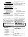
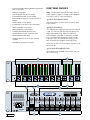
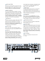
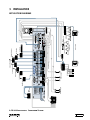
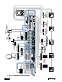
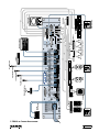
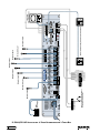
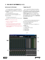
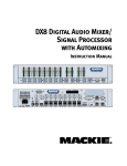
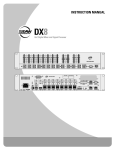
DX810 Digital Audio Mixer/
Signal Processor
Instruction Manual
OL
OL
OL
OL
OL
OL
OL
2
4
7
10
15
20
25
30
35
40
50
2
4
7
10
15
20
25
30
35
40
50
2
4
7
10
15
20
25
30
35
40
50
2
4
7
10
15
20
25
30
35
40
50
2
4
7
10
15
20
25
30
35
40
50
2
4
7
10
15
20
25
30
35
40
50
2
4
7
10
15
20
25
30
35
40
50
OL
15
12
9
6
3
2
4
7
10
15
20
25
30
35
40
50
0
3
6
9
12
15
DX8 DIGITAL MIXER
A
1
2
3
4
5
6
7
8
LO
EQ
HI
A
MASTER
B
LOCK
MODE
B
POWER
COMM PORT
1 2 3 4 5 6 7 8
SERIAL NUMBER
MANUFACTURING DATE
– +
DIRECT OUTPUTS
U
THE FOLLOWING ARE TRADEMARKS OR REGISTERED
TRADEMARKS OF MACKIE DESIGNS INC "MACKIE",
"MACKIE INDUSTRIAL", AND THE "RUNNING MAN" FIGURE
CONCEIVED, DESIGNED, AND MANUFACTURED
BY MACKIE DESIGNS INC WOODINVILLE • WA • USA
MADE IN USA • FABRIQUE AU USA • COPYRIGHT ©1999
U
+20
TRIM
BUS A
POWER
R
, 50/60Hz, 1A MAX
LISTED COMMERCIAL
AUDIO EQUIPMENT
9Z39
U
U
U
U
U
U
–
-20
+20
TRIM
BUS B
MIC
+ G
LINE
G +
C GAIN
MI
C GAIN
MI
C GAIN
MI
C GAIN
MI
C GAIN
MI
C GAIN
MI
C GAIN
MI
C GAIN
MI
60
0
-30dB +30dB
60
0
-30dB +30dB
60
0
-30dB +30dB
60
0
-30dB +30dB
60
0
-30dB +30dB
60
0
-30dB +30dB
60
0
-30dB +30dB
60
0
-30dB +30dB
TRIM
TRIM
TRIM
TRIM
TRIM
TRIM
TRIM
TRIM
MIC
MIC
MIC
MIC
MIC
MIC
MIC
MIC
1
2
3
4
5
6
7
G
8
–
G 11
INPUTS
OUTPUTS
A
LINE
LINE
LINE
LINE
LINE
LINE
LINE
D
1 +5V
G
1
B
1 2 3 4 5 6 7 8
LINE
C
H
G
+
E
F
–
REMOTE BUS
COMM PORT
OUTPUTS
ON
LINE
+ –
I
LOGIC I/O
PHANTOM POWER
48V DC
–
+
LINE
J
U
12
-20
INPUT
22-28V DC,
3A MAX
100 – 240V
U
G
•10e
DX8 DIGITAL MIXER
RECORD
A
G
+
–
B
G
+
–
CAUTION
AVIS
RISK OF ELECTRIC SHOCK
DO NOT OPEN
RISQUE DE CHOC ELECTRIQUE
NE PAS OUVRIR
CAUTION: TO REDUCE THE RISK OF ELECTRIC SHOCK
DO NOT REMOVE COVER (OR BACK)
NO USER-SERVICEABLE PARTS INSIDE
REFER SERVICING TO QUALIFIED PERSONNEL
ATTENTION: POUR EVITER LES RISQUES DE CHOC
ELECTRIQUE, NE PAS ENLEVER LE COUVERCLE. AUCUN
ENTRETIEN DE PIECES INTERIEURES PAR L'USAGER. CONFIER
L'ENTRETIEN AU PERSONNEL QUALIFIE.
AVIS: POUR EVITER LES RISQUES D'INCENDIE OU
D'ELECTROCUTION, N'EXPOSEZ PAS CET ARTICLE
A LA PLUIE OU A L'HUMIDITE
The lightning flash with arrowhead symbol within an equilateral
triangle is intended to alert the user to the presence of uninsulated
"dangerous voltage" within the product's enclosure, that may be
of sufficient magnitude to constitute a risk of electric shock to persons.
Le symbole éclair avec point de flèche à l'intérieur d'un triangle
équilatéral est utilisé pour alerter l'utilisateur de la présence à
l'intérieur du coffret de "voltage dangereux" non isolé d'ampleur
suffisante pour constituer un risque d'éléctrocution.
7. Heat — Locate the DX810 away from heat sources such as radiators, or other
devices which produce heat.
8. Power Sources — Connect the DX810 to a power supply only of the type described
in these operation instructions or as marked on the rear panel. If using an external DC
power supply or battery pack, be sure the voltage corresponds to the range indicated on
the rear panel, and that it is connected with the correct polarity.
9. Power Cord Protection — Route power supply cords so that they are not likely to be
walked upon or pinched by items placed upon or against them, paying particular attention
to cords at plugs, convenience receptacles, and the point where they exit the DX810.
10. Object and Liquid Entry — Do not drop objects into or spill liquids into the inside
of the DX810.
11. Damage Requiring Service — The DX810 should be serviced only by qualified
service personnel when:
A. The power-supply cord or the plug has been damaged; or
B. Objects have fallen, or liquid has spilled into the DX810; or
C. The DX810 has been exposed to rain; or
The exclamation point within an equilateral triangle is intended to
alert the user of the presence of important operating and maintenance
(servicing) instructions in the literature accompanying the appliance.
Le point d'exclamation à l'intérieur d'un triangle équilatéral est
employé pour alerter les utilisateurs de la présence d'instructions
importantes pour le fonctionnement et l'entretien (service) dans le
livret d'instruction accompagnant l'appareil.
1. SAFETY INSTRUCTIONS
1. Read Instructions — Read all the safety and operation instructions before
operating the DX810.
2. Retain Instructions — The safety and operating instructions should be kept for
future reference.
3. HEED ALL WARNINGS — Follow all warnings on the DX810 and in these operating
instructions.
4. FOLLOW ALL INSTRUCTIONS — Follow all operating and other instructions.
5. Water and Moisture — Do not use the DX810 near water – for example, near a
bathtub, washbowl, kitchen sink, laundry tub, in a wet basement, near a swimming
pool, etc.
6. Ventilation — This DX810 should be situated so that its location or position
does not interfere with its proper ventilation. For example, it should not be
situated on a bed, sofa, rug, or similar surface that may block any ventilation
openings, or placed in a built-in installation such as a bookcase or cabinet that
may impede the flow of air through ventilation openings.
WARNING — To reduce the risk of fire or electric
shock, do not expose this appliance to rain or moisture.
D. The DX810 does not appear to operate normally or exhibits a marked
change in performance; or
E. The DX810 has been dropped, or its chassis damaged.
12. Servicing — The user should not attempt to service the DX810 beyond those
means described in this operating manual. All other servicing should be referred to the
Mackie Service Department.
13. To prevent electric shock, do not use this polarized plug with an extension cord,
receptacle or other outlet unless the blades can be fully inserted to prevent blade
exposure.
Pour prévenir les chocs électriques ne pas utiliser cette fiche polariseé avec un
prolongateur, un prise de courant ou une autre sortie de courant, sauf si les lames
peuvent être insérées à fond sans laisser aucune pariie à découvert.
14. Grounding or Polarization — Precautions should be taken so that the grounding or
polarization means of the DX-810 is not defeated.
15. This apparatus does not exceed the Class A/Class B (whichever is applicable)
limits for radio noise emissions from digital apparatus as set out in the radio
interference regulations of the Canadian Department of Communications.
ATTENTION —Le présent appareil numérique n’émet pas de bruits radioélectriques
dépassant las limites applicables aux appareils numériques de class A/de class B (selon
le cas) prescrites dans le règlement sur le brouillage radioélectrique édicté par les
ministere des communications du Canada.
CAUTION — Internal lithium battery.
Danger of explosion if battery is incorrectly replaced.
Replace only with the same or equivalent type.
Using the REMOTE BUS Connection ............................. 16
TABLE OF CONTENTS
Using the LOGIC I/O ......................................................... 16
Front Panel Lock ............................................................... 17
1. SAFETY INSTRUCTIONS ............................................. 2
2.
INTRODUCTION ....................................................... 3
KEY FEATURES ................................................................... 4
Upgrading the Software .................................................. 17
5.
Installing the Software ..................................................... 18
FRONT PANEL FEATURES ................................................. 4
Connecting a PC ............................................................... 18
REAR PANEL FEATURES ................................................... 5
Overview ........................................................................... 18
SIGNAL-FLOW DIAGRAM ................................................. 6
3.
Menu Bar .......................................................................... 19
INSTALLATION ......................................................... 7
APPLICATION DIAGRAMS ................................................. 7
Connections ...................................................................... 12
Button Section .................................................................. 22
6.
OPERATION ............................................................. 14
Quick Start ........................................................................ 14
Using the Digital Signal Processors ............................... 15
Using the BUS A and B Inputs ........................................ 15
DX810 – 2
Using the RECORD Output .............................................. 16
OUTPUTS A and B ........................................................... 16
SPECIFICATIONS ..................................................... 30
DX810 Block Diagram ...................................................... 30
AC Power Considerations ................................................ 13
4.
DX-10E-PC SOFTWARE (v 1.00) .............................. 18
DX810 Specifications ....................................................... 31
7.
Service Information ................................................ 33
Appendix A: Logic Input Functions ........................................... 34
Appendix B: Logic Output Functions ........................................ 34
Appendix C: Selection Remote Predefined Functions ............ 34
Appendix D: Level Remote Predefined Functions ................... 35
2. INTRODUCTION
The DX810 is our popular DX8 stereo digital
audio mixer with the DX10e Expansion Kit installed.
This adds eight more balanced outputs and
converts it into a powerful matrix mixer/processor.
It is designed for use in a variety of installations
such as churches, courtrooms, convention centers,
and hotels. With eight inputs, ten outputs, and a
toolbox full of DSP, the DX810 fits most any
installed sound reinforcement application.
Each of the 10 outputs represents a discrete mix
of the eight inputs, resulting in a true 8x10 mixing
matrix with virtual faders at each crosspoint. It has
the ability to group any combination of gain
elements to one of 32 groups.
A new software interface provides intuitive
setup and operation via a PC. Third-octave and fiveband parametric EQs are provided on each output.
There is also a three band sweepable high and low
shelving EQ with a fully parametric mid-range control
on each input.
The processing power provided by the DX810
permits inserting a gate on each input, as well as a
compressor on each input and output. It also
permits inserting signal delay on each output, and
creating crossover groups with custom high, low, or
bandpass filters applied to each output. Up to five
outputs can be assigned to a crossover group.
Each of the eight input channels is terminated to
two Phoenix-type detachable connectors. Each
connector is optimized to accept either microphone
or line-level signals. Microphone preamplifiers utilize
Mackie’s proprietary XDR™ technology to offer
studio-class audio performance. Phantom power of
48 VDC is switchable individually on each input.
Two auxiliary line-level inputs with trim are provided,
allowing analog signals to be mixed with the A and
B master mixes. All main outputs deliver balanced
line-level signals to detachable Phoenix-type
connectors. The main A and B outputs also deliver
buffered unbalanced signals to RCA connectors
intended for recording.
The DX810 offers an intuitive front panel user
interface for the A and B outputs. It consists of
dual-function LED bar graph meters for each input
and the A and B outputs. Input meters indicate the
presence of signal before signal processing (prefader). Output meters indicate the actual level at
output (post-fader). Levels are set by means of UP/
DOWN pushbuttons dedicated to each input and
output. A MODE button is used to select between
Mix A and B. This allows adjustment of levels to
both mix outputs from the same set of input
controls. A third function of the MODE button
allows the user to LOCK the front panel controls
until a security unlock code is entered.
The DX810 offers flexible interface options
through dedicated inputs and outputs for control
and programming purposes. Two independent
RS232 connectors are provided, one on the front
panel and one on the rear, for connection to a
computer or control system. A multi-pin (DB25F)
connector on the rear panel allows interface among
the 10 Logic Inputs and 10 Logic Outputs. This
interface connects to switches, LEDs, and other
devices, enabling hardware control and indication
from custom control panels. All logic inputs and
outputs are programmable in software. A proprietary
remote control bus allows connection of the
optional wired remotes over three-conductor cable.
Remotes are available in Volume Control (DX-RVC)
and 4-Switch (DX-SW4) versions and may be
combined in any configuration.
The DX810 is supplied with DX-10E-PC software
that allows access to all of the system’s settings
and configurations. The software provides access to
the 3-band input EQ, 31-band graphic EQ, compressors, gates, delays, and crossover configuration. In
addition, it allows saving and recalling up to 32
presets, configuration for 32 control groups, for
input force on/force off functions with priority, and
for the logic input and output connections. All
settings and text labels are retained in the DX810 as
well as stored on the computer's local drive.
The DX810 is UL and CE approved and designed
for continuous use in professional fixed installation
systems. An internal auto-ranging power supply
allows connection to mains voltages from 90-240 VAC
at 50/60 Hz. This is without requiring jumper or
switch setting changes. A 24 VDC input is
provided for applications where backup power is
required. Switchover to backup power is automatic
and silent.
KEY FEATURES
•
32-bit DSP and 24-bit Analog/Digital Conversion
•
8 balanced XDR™ Mic/Line inputs with trim
•
2 balanced Line inputs direct to mix buses A and B
•
10 Independent Mix Buses and balanced Outputs
•
2 unbalanced Record Outputs
•
8 unbalanced Direct Channel Outputs
•
Individual Level/Peak (PPM) metering on each Input
Part No. 0001335 Rev. A1 03/02
© 2002 All Rights Reserved. Mackie Industrial.
DX810 – 3
•
2-band sweepable shelving EQ with a parametric
mid on each Input
FRONT PANEL FEATURES
•
Gating on each Input
•
31-band Graphic EQ on each Output
•
5-band Parametric EQ on each Output
Note: The front panel controls only apply to the A
and B outputs. Outputs C through J are controlled
with the DX-10E-PC software interface.
•
Fully variable Compressor on each Input and
Output
•
Variable delay on each Output
•
Configurable crossover for up to five bands
•
10 Programmable Logic Inputs
•
10 Programmable Logic Outputs
•
2 independent RS-232 interface ports
•
48 VDC Phantom Power switch per input
•
24 VDC Backup Power input
•
Hardware Expansion Port accepts optional
modules
•
PC Software application included
INPUT UP/DOWN BUTTONS
Use these buttons to adjust the mix level for each
input channel.
INPUT LED DISPLAY
This indicates the signal level after the mic preamp
stage, just after the A/D converter, but prior to any
digital signal processing. When any input UP/
DOWN button is pressed, all the meters (except
EQ) switch from level metering to level setting
indication. After five seconds, the meters switch
back to normal peak program metering (PPM).
When the 10 and 7 LEDs are both lit, the gain is set
to unity (0 dB).
EQ LO/HI UP/DOWN BUTTONS
These buttons are disabled in the DX810 (they are
for DX8 use only).
OL
OL
OL
OL
OL
OL
OL
2
4
7
10
15
20
25
30
35
40
50
2
4
7
10
15
20
25
30
35
40
50
2
4
7
10
15
20
25
30
35
40
50
2
4
7
10
15
20
25
30
35
40
50
2
4
7
10
15
20
25
30
35
40
50
2
4
7
10
15
20
25
30
35
40
50
2
4
7
10
15
20
25
30
35
40
50
1
2
3
4
5
6
3
6
9
12
15
7
8
LO
-20
+20
TRIM
BUS A
POWER
INPUT
22-28V DC,
3A MAX
100 – 240V
R
DX810 – 4
, 50/60Hz, 1A MAX
LISTED COMMERCIAL
AUDIO EQUIPMENT
9Z39
–
MIC
+ G
G
LINE
+
-20
+20
TRIM
BUS B
HI
A
MASTE
MANUFACTURING DATE
10e
DX8 DIGITAL MIXER
DIRECT OUTPUTS
THE FOLLOWING ARE TRADEMARKS OR REGISTERED
TRADEMARKS OF MACKIE DESIGNS INC "MACKIE",
"MACKIE INDUSTRIAL", AND THE "RUNNING MAN" FIGURE
CONCEIVED, DESIGNED, AND MANUFACTURED
BY MACKIE DESIGNS INC WOODINVILLE • WA • USA
MADE IN USA • FABRIQUE AU USA • COPYRIGHT ©1999
EQ
SERIAL NUMBER
U
2
4
7
10
15
20
25
30
35
40
50
0
1 2 3 4 5 6 7 8
U
OL
15
12
9
6
3
U
U
U
U
U
U
U
U
C GAIN
MI
C GAIN
MI
C GAIN
MI
C GAIN
MI
C GAIN
MI
C GAIN
MI
C GAIN
MI
C GAIN
MI
60
0
-30dB +30dB
60
0
-30dB +30dB
60
0
-30dB +30dB
60
0
-30dB +30dB
60
0
-30dB +30dB
60
0
-30dB +30dB
60
0
-30dB +30dB
60
0
-30dB +30dB
TRIM
TRIM
TRIM
TRIM
TRIM
TRIM
TRIM
TRIM
MIC
MIC
MIC
MIC
MIC
MIC
MIC
MIC
LINE
LINE
LINE
LINE
LINE
LINE
LINE
LINE
1
2
3
4
5
6
7
8
–
–
+
LINE
LINE
17 for more information on locking and unlocking
the DX810.
EQ LED DISPLAY
This display is disabled in the DX810 (it is for DX8
use only).
MASTER A/B UP/DOWN BUTTONS
These buttons adjust the output level for the A and
B output buses.
MASTER OUTPUT LED DISPLAY
This indicates the signal level after the digital signal
processing and MASTER A and B gain stage, just
prior to the D/A converter. When any MASTER UP/
DOWN button is pressed, all the meters switch
from level metering to level setting indication. After
five seconds, the meters switch back to normal
peak program metering (PPM).
COMM PORT
This is an RS-232 port on a 9-pin D-Sub connector.
It connects to a personal computer or other
compatible control system for external control of
the DX810 settings. A second COMM port on the
rear panel duplicates this function, for permanent
connection to an installed controller.
POWER
Use the POWER switch to turn the DX810 on
and off.
REAR PANEL FEATURES
MODE
This switch changes the front panel operation
between Bus A and Bus B operation. In addition,
the LOCK position disables the front panel controls
to prevent unauthorized changes to the settings. A
security code must be entered to enable the front
panel controls when the DX810 is locked. See page
INPUTS 1-8
Each of the eight analog inputs has separate
balanced mic and line input connectors that use
Mackie’s acclaimed XDR mic preamps. These are
3-pin Phoenix-type connectors. Use either the MIC
or LINE input, but only one can be used per channel.
TRIM
This rotary analog control is used to trim
the gain of the input signal for optimum
signal-to-noise ratio in the preamp stage.
For mic-level signals, it provides from 0 to
+60 dB of gain. For line-level signals, it
provides from –30 dB to +30 dB of gain.
Unity (0 dB) is at the center position. This
control accepts a maximum input signal of
+18 dBu before clipping (at unity gain).
OL
2
4
7
10
15
20
25
30
35
40
50
DX8 DIGITAL MIXER
A
A
MASTER
B
LOCK
PHANTOM POWER
MODE
B
POWER
COMM PORT
BUS A/B INPUTS
TURING DATE
– +
G
J
I
H
G
•10e
U
N
C GAIN
MI
G
12
0
0dB
INPUTS
+ –
C
D
1 +5V
G
E
+
F
–
60
0
-30dB +30dB
TRIM
8
G 11
MIC
OUTPUTS
1
REMOTE BUS
LOGIC I/O
PHANTOM POWER
48V DC
These switches apply phantom power
(+48 VDC) to pins 2 and 3 of the selected
mic input connectors. Put the PHANTOM
POWER switch in the UP position for an
individual channel when using a
condenser microphone.
COMM PORT
These analog inputs accept balanced linelevel signals and route the signal to the
internal A and B buses. These inputs may
serve as additional zone inputs for program
devices. There is no DSP processing on
these inputs.
OUTPUTS
A
B
A
G
+
–
B
G
+
–
ON
1 2 3 4 5 6 7 8
LINE
RECORD
DX810 – 5
of each logic input and output can be programmed
via software to suit individual applications. See
page 13 for the Logic I/O pinouts.
BUS A and B TRIM
These rotary analog controls are used to trim the
gain of the inputs to the A and B buses. This trim
control provides from –20 dB to +20 dB of gain,
with unity (0 dB) at the center-detent position.
REMOTE BUS
DIRECT OUTPUTS
This 15-pin D-Sub connector supplies an analog,
unbalanced line-level signal from each of the eight
program inputs, post-preamp and pre-processing.
Use these outputs to connect to another mixing
console for additional zone coverage, a telephone
system for music-on-hold, or a multi-track recorder.
See page 12 for the Direct Output pinouts.
RECORD Out
These RCA connectors supply unbalanced line-level
signals from the A and B outputs. Use these
outputs to connect to the inputs of a recorder. They
can also act as additional line-level outputs to
connect to an external power amplifier. The signals
are the same as the main outputs.
OUTPUTS A/B
These 3-pin Phoenix-type connectors supply a
balanced line-level signal from OUTPUTS A and B.
LOGIC I/O
This 25-pin D-Sub connector provides 10 logic
control inputs and 10 logic control outputs (opencollector). These inputs can be used to control a
wide variety of DX810 functions via external
switching. The outputs can be used to provide
status levels for external indicators for a number of
internal settings and conditions. They can also
control switching to external devices. The function
This 3-pin Phoenix-type connector can be used to
attach optional remote controls to the DX810.
Several remote controls can be connected to each
other in a daisy-chain fashion to extend the remote
control functionality of the DX810.
COMM PORT
This is identical to the COMM PORT on the front
panel. Use this to connect to an RS-232 serial port
on a personal computer or third-party controller (i.e.,
show controller) for external control of the DX810.
DX10e Expansion Panel
The DX10e provides eight additional independent
balanced output mixes, (C-J).
24 VDC POWER
The DX810 can be powered using a 24 VDC power
supply. This can serve as the primary power supply
for the DX810, or as a backup supply in case of an
AC power failure. The DX810 seamlessly switches
to the backup supply if there’s a power loss. When
both AC power and 24 VDC power are connected,
the AC power is used and no current is drawn from
the DC supply.
IEC AC Socket
Connect the supplied AC linecord to the IEC
AC socket.
1 2 3 4 5 6 7 8
SERIAL NUMBER
DIRECT OUTPUTS
U
THE FOLLOWING ARE TRADEMARKS OR REGISTERED
TRADEMARKS OF MACKIE DESIGNS INC "MACKIE",
"MACKIE INDUSTRIAL", AND THE "RUNNING MAN" FIGURE
CONCEIVED, DESIGNED, AND MANUFACTURED
BY MACKIE DESIGNS INC WOODINVILLE • WA • USA
MADE IN USA • FABRIQUE AU USA • COPYRIGHT ©1999
U
+20
TRIM
BUS A
POWER
R
DX810 – 6
, 50/60Hz, 1A MAX
LISTED COMMERCIAL
AUDIO EQUIPMENT
9Z39
–
-20
+20
U
U
U
TRIM
BUS B
MIC
+ G
LINE
G +
U
U
U
U
C GAIN
MI
C GAIN
MI
C GAIN
MI
C GAIN
MI
C GAIN
MI
C GAIN
MI
C GAIN
MI
60
0
-30dB +30dB
60
0
-30dB +30dB
60
0
-30dB +30dB
60
0
-30dB +30dB
60
0
-30dB +30dB
60
0
-30dB +30dB
60
0
-30dB +30dB
TRIM
TRIM
TRIM
TRIM
TRIM
TRIM
TRIM
TRIM
MIC
MIC
MIC
MIC
MIC
MIC
MIC
MIC
2
3
G
J
+
–
C
4
5
6
7
G
8
–
G 11
INPUTS
OUTPUTS
A
LINE
LINE
LINE
LINE
LINE
LINE
LINE
G
1
B
1 2 3 4 5 6 7 8
LINE
H
G
+
E
F
–
REMOTE BUS
COMM PORT
OUTPUTS
ON
LINE
D
1 +5V
LOGIC I/O
PHANTOM POWER
48V DC
–
+
LINE
I
U
C GAIN
MI
60
0
-30dB +30dB
1
– +
•10e
12
-20
INPUT
22-28V DC,
3A MAX
100 – 240V
MANUFACTURING DATE
DX8 DIGITAL MIXER
RECORD
A
G
+
–
B
G
+
–
4-Track Recorder
LISTED COMMERCIAL
AUDIO EQUIPMENT
9Z39
, 50/60Hz, 1A MAX
Mix Minus Outputs
R
100 – 240V
–
+
THE FOLLOWING ARE TRADEMARKS OR REGISTERED
TRADEMARKS OF MACKIE DESIGNS INC "MACKIE",
"MACKIE INDUSTRIAL", AND THE "RUNNING MAN" FIGURE
CONCEIVED, DESIGNED, AND MANUFACTURED
BY MACKIE DESIGNS INC WOODINVILLE • WA • USA
MADE IN USA • FABRIQUE AU USA • COPYRIGHT ©1999
24VDC
Power Supply
POWER
INPUT
22-28V DC,
3A MAX
+20
U
LINE
LINE
+
G
–
MIC
+ G
–
BUS A
TRIM
-20
+20
U
1
LINE
MIC
TRIM
0
60
-30dB +30dB
C GAIN
MI
U
MIC
LINE
LINE
LINE
–10
–8
–6
–3
0
– 5
– 10
– 15
– 20
– 25
– 30
– 40
Judge
Video Switcher
Security Monitoring
4
TRIM
MIC
3
TRIM
MIC
2
TRIM
5
LINE
MIC
TRIM
0
60
-30dB +30dB
C GAIN
MI
C GAIN
MI
0
60
-30dB +30dB
C GAIN
MI
U
U
0
60
-30dB +30dB
U
0
60
-30dB +30dB
C GAIN
MI
U
DX8 DIGITAL MIXER
Mix Minus Outputs
LINE
BUS B
TRIM
-20
DIRECT OUTPUTS
1 2 3 4 5 6 7 8
Camera 2
+
Camera 3
Judge's Microphone
Clerk's Microphone
Camera 4
–
Prosecution's Microphone
Witness's Microphone
Camera 1
Defense's Microphone
6
VCR
LINE
MIC
TRIM
0
60
-30dB +30dB
C GAIN
MI
U
SERIAL NUMBER
7
LINE
MIC
TRIM
0
60
-30dB +30dB
C GAIN
MI
U
C GAIN
MI
U
8
LINE
MIC
TRIM
1 2 3 4 5 6 7 8
ON
PHANTOM POWER
48V DC
G 11
12
OUTPUTS
INPUTS
•10
0e
RECORD
+
–
G
1
1 +5V
B
G
– +
D
+
–
E
H
G
+
–
REMOTE BUS
G
I
OUTPUTS
A
C
J
B
Remote Controls
G
+
–
COMM PORT
F
G
Clerk
–10
–8
–6
–3
0
– 5
– 10
– 15
– 20
– 25
– 30
– 40
Cassette Deck
Laptop with
DX-10E-PC Application
UP4061 Gallery
AM4160
Paging Feed/Witness Call
A
LOGIC I/O
Ceiling Speakers
0
60
-30dB +30dB
MANUFACTURING DATE
Tape Playback
Jury's Microphone
Defendant's Microphone
3. INSTALLATION
APPLICATION DIAGRAMS
A: DX-810 Application: Courtroom System
DX810 – 7
B: Typical Community Center Application
DX810 – 8
–
Music On Hold
24VDC
Power Supply
–10
–8
–6
–3
0
– 5
– 10
– 15
– 20
– 25
– 30
– 40
R
100 – 240V
–
+
LINE
–
MIC
+ G
LINE
G +
–
BUS A
M1400i
POWER
INPUT
22-28V DC,
3A MAX
+20
U
+20
LINE
TRIM
–10
–8
–6
–3
0
– 5
– 10
– 15
– 20
– 25
– 30
– 40
BUS B
-20
U
DIRECT OUTPUTS
1 2 3 4 5 6 7 8
TRIM
-20
Gymnasium
Two-Way
Stereo System
M1400i
LISTED COMMERCIAL
AUDIO EQUIPMENT
9Z39
, 50/60Hz, 1A MAX
THE FOLLOWING ARE TRADEMARKS OR REGISTERED
TRADEMARKS OF MACKIE DESIGNS INC "MACKIE",
"MACKIE INDUSTRIAL", AND THE "RUNNING MAN" FIGURE
CONCEIVED, DESIGNED, AND MANUFACTURED
BY MACKIE DESIGNS INC WOODINVILLE • WA • USA
MADE IN USA • FABRIQUE AU USA • COPYRIGHT ©1999
+
Digital Satellite Service
U
LINE
MIC
3
TRIM
0
60
-30dB +30dB
C GAIN
MI
Weight Room
MR4T
UP4161
LINE
MIC
MIC
LINE
TRIM
TRIM
2
0
60
-30dB +30dB
0
60
-30dB +30dB
1
U
C GAIN
MI
U
C GAIN
MI
DX8 DIGITAL MIXER
CD Player
U
U
UP4161
LINE
MIC
5
TRIM
0
60
-30dB +30dB
C GAIN
MI
SERIAL NUMBER
LINE
MIC
6
TRIM
0
60
-30dB +30dB
C GAIN
MI
U
–10
–8
–6
–3
0
– 5
– 10
– 15
– 20
– 25
– 30
– 40
VAC
LINE
MIC
7
TRIM
0
60
-30dB +30dB
C GAIN
MI
U
C GAIN
MI
8
Pool - MR4T
G 11
12
PHANTOM POWER
48V DC
A
+ –
G
1
1 +5V
B
G
RECORD
LOGIC I/O
OUTPUTS
INPUTS
•10
0e
– +
D
+
–10
–8
–6
–3
0
– 5
– 10
– 15
– 20
– 25
– 30
– 40
–
E
H
G
+
–
REMOTE BUS
G
I
OUTPUTS
A
C
J
Meeting Room B - MR4T
1 2 3 4 5 6 7 8
ON
UP4161
LINE
MIC
TRIM
0
60
-30dB +30dB
MANUFACTURING DATE
U
Telephone Paging
Contact
Line Input From Gym
Telephone Paging
Feed
Paging Mic
Lobby Ceiling Speakers
LINE
MIC
4
TRIM
0
60
-30dB +30dB
C GAIN
MI
Cassette or DAT Recorder
Wireless Microphone
Receivers
VAC
Visual
Paging
Indicator
Zone Page
Select Buttons
G
+
–
–10
–8
–6
–3
0
– 5
– 10
– 15
– 20
– 25
– 30
– 40
Remote Controls
Meeting Room A - MR4T
B
COMM PORT
F
G
Laptop with
DX-10E-PC Application
C: DX810 in Church Application
DX810 – 9
–
24VDC
Power Supply
–10
–8
–6
–3
0
– 5
– 10
– 15
– 20
– 25
– 30
– 40
PA121
R
100 – 240V
PA121
M1400i
LISTED COMMERCIAL
AUDIO EQUIPMENT
9Z39
, 50/60Hz, 1A MAX
–
+
THE FOLLOWING ARE TRADEMARKS OR REGISTERED
TRADEMARKS OF MACKIE DESIGNS INC "MACKIE",
"MACKIE INDUSTRIAL", AND THE "RUNNING MAN" FIGURE
CONCEIVED, DESIGNED, AND MANUFACTURED
BY MACKIE DESIGNS INC WOODINVILLE • WA • USA
MADE IN USA • FABRIQUE AU USA • COPYRIGHT ©1999
+
G
LINE
LINE
+
–
PA180SW
–
MIC
+ G
M2600
POWER
INPUT
22-28V DC,
3A MAX
+20
BUS A
TRIM
-20
U
+20
LINE
TRIM
BUS B
-20
U
DIRECT OUTPUTS
1 2 3 4 5 6 7 8
MR4T
Delay 1
UP4061
LINE
MIC
MIC
LINE
TRIM
TRIM
2
0
60
-30dB +30dB
0
60
-30dB +30dB
1
U
C GAIN
MI
U
3
LINE
MIC
TRIM
0
60
-30dB +30dB
C GAIN
MI
U
U
4
LINE
MIC
TRIM
0
60
-30dB +30dB
C GAIN
MI
UP4061
DX8 DIGITAL MIXER
C GAIN
MI
Wireless Microphone
Receiver
Pulpit Microphone
Lectern Microphone
U
C GAIN
MI
5
–10
–8
–6
–3
0
– 5
– 10
– 15
– 20
– 25
– 30
– 40
MR4T
Delay 2
LINE
MIC
TRIM
0
60
-30dB +30dB
Baptismal Microphone
6
LINE
MIC
TRIM
0
60
-30dB +30dB
C GAIN
MI
U
SERIAL NUMBER
7
U
8
LINE
MIC
TRIM
0
60
-30dB +30dB
C GAIN
MI
1 2 3 4 5 6 7 8
ON
PHANTOM POWER
48V DC
G 11
12
+
–
G
1
1 +5V
D
+
–
E
H
+
B
G
+
–
COMM PORT
F
G
Cassette Deck
Laptop with
DX-10E-PC Application
Remote Controls
–10
–8
–6
–3
0
– 5
– 10
– 15
– 20
– 25
– 30
– 40
PACX81 Floor Monitors
M1400i
G
–
REMOTE BUS
G
I
OUTPUTS
A
C
J
AM4160
B
G
– +
RECORD
Fellowship Hall Ceiling Speakers
((( )))
A
LOGIC I/O
OUTPUTS
INPUTS
•10
0e
Mackie 24•4 Mixer
Hearing Assistance Transmitter
LINE
MIC
TRIM
0
60
-30dB +30dB
C GAIN
MI
U
MANUFACTURING DATE
CD Player
Choir Microphone
D: DX810/DX-10E Application : 8-Track Recording with 2-Track Mix
DX810 – 10
–
24VDC
Power Supply
LISTED COMMERCIAL
AUDIO EQUIPMENT
9Z39
, 50/60Hz, 1A MAX
–
+
POWER
INPUT
22-28V DC,
3A MAX
+20
LINE
LINE
+
G
–
MIC
+ G
–
BUS A
TRIM
-20
U
LINE
TRIM
+20
BUS B
-20
U
DIRECT OUTPUTS
1 2 3 4 5 6 7 8
Monitor 2-track mix through phones
connected to 2-track recorder.
2- Track Recorder
R
100 – 240V
THE FOLLOWING ARE TRADEMARKS OR REGISTERED
TRADEMARKS OF MACKIE DESIGNS INC "MACKIE",
"MACKIE INDUSTRIAL", AND THE "RUNNING MAN" FIGURE
CONCEIVED, DESIGNED, AND MANUFACTURED
BY MACKIE DESIGNS INC WOODINVILLE • WA • USA
MADE IN USA • FABRIQUE AU USA • COPYRIGHT ©1999
+
Microphone Input 1
U
3
LINE
MIC
TRIM
0
60
-30dB +30dB
C GAIN
MI
8-Track Recorder
LINE
MIC
MIC
LINE
TRIM
TRIM
2
0
60
-30dB +30dB
0
60
-30dB +30dB
1
U
C GAIN
MI
U
C GAIN
MI
DX8 DIGITAL MIXER
Microphone Input 2
Microphone Input 3
Microphone Input 4
U
4
LINE
MIC
TRIM
0
60
-30dB +30dB
C GAIN
MI
U
5
LINE
MIC
TRIM
0
60
-30dB +30dB
C GAIN
MI
–10
–8
–6
–3
0
– 5
– 10
– 15
– 20
– 25
– 30
– 40
6
LINE
MIC
TRIM
0
60
-30dB +30dB
C GAIN
MI
U
SERIAL NUMBER
7
U
8
LINE
MIC
TRIM
0
60
-30dB +30dB
C GAIN
MI
1 2 3 4 5 6 7 8
ON
PHANTOM POWER
48V DC
G 11
12
A
+
–
G
1
1 +5V
B
G
– +
RECORD
LOGIC I/O
OUTPUTS
INPUTS
•10
0e
D
+
–
E
H
G
+
–
REMOTE BUS
G
I
OUTPUTS
A
C
J
Remote Controls for Group Level Control and Preset Recall
LINE
MIC
TRIM
0
60
-30dB +30dB
C GAIN
MI
U
MANUFACTURING DATE
Microphone Input 8
Microphone Input 7
Microphone Input 6
Microphone Input 5
B
G
+
–
COMM PORT
F
G
–10
–8
–6
–3
0
– 5
– 10
– 15
– 20
– 25
– 30
– 40
Laptop with
DX-10E-PC Application
Applications
A: DX-810 Application: Courtroom System
This example employs seven microphones
connected to the MIC inputs of the DX810. All
microphones in all examples can be any combination of
dynamic and/or condensor microphones. Phantom
Power is selected for the appropriate inputs that use
condensor microphones. This applies to all the following
examples also.
A cassette tape playback signal is routed to Input 8.
A 4-track recorder taps off of four of the input signals
via the DIRECT OUTPUTS jack.
Remote Control functions are provided to the Judge
and Clerk, each shown with a DX-SW4 and DX-RVC.
These could be configured to mute inputs or outputs and
adjust volumes of selected gain elements.
Logic Outputs control a video switcher for camera
selection to the VCR, which derives its audio feed from
Outputs I and J.
Outputs A through E are routed to a series of
amplifiers and speakers for Mix Minus distribution for
feedback control throughout the courtroom. Output F is
routed to a Security Monitoring location. Output G is
routed to a Mackie Industrial UP4061amplifier that feeds
the Gallery ceiling speakers. Output H is a paging feed to
the Witness Call ceiling speakers.
B: DX-810 Application: Community Center System
This example employs several music sources, (a
satellite system, a CD player, and a cassette player
connected to Line Inputs 1, 2, and 3). It also uses two
wireless microphones, and a paging microphone
connected to MIC inputs 4, 5 and 6. A telephone system
paging output is connected to Input 7. Line Input 8
shows an auxiliary signal feed from the Gymnasium (to
provide a signal from an external mixer, for instance).
A Music On Hold feed to the telephone system is
shown being tapped off of a Direct Output.
Five sets of remotes, consisting of a DX-SW4 and
DX–RVC are shown connected to the Remote Bus.
These could be configured to select different input
sources and adjust volume levels in different zones.
Logic Inputs are shown as paging control contacts
closures. One is from the telephone system, and the
rest are for routing the paging microphone input to
different zones of the system.
A Logic Output is shown as controlling a visual
paging indicator.
Outputs A and B are connected to a pair of Mackie
M-1400i amplifiers. This feeds a stereo bi-amped
speaker system in the Gymnasium. Output D is routed
to a Mackie Industrial UP4161. This feeds a 70-Volt
distributed speaker system in the Weight Room. It uses
several Mackie Industrial Monitor 4T speakers. Output F
is shown feeding the lobby ceiling speakers via a 70-Volt
output of a Mackie Industrial UP4161. Outputs G and H
are routed to two Mackie Industrial AM4060 mixeramps. These amps then feed four Monitor 4T speakers
each in Meeting Rooms A and B. The AM4060 allows
for local microphone inputs in each meeting room. There
is also a feed from the main system with separate
volume controls. Output I shows a series of Monitor 4T’s
being powered by a UP4161 in the Pool area.
C: DX810 Application: Small Church System
This example employs five microphones connected
to MIC inputs 1 through 5 of the DX810. MIC input 1 is a
wireless lavalier mic, inputs 2, 3, and 4 are stand
mounted hand-held mics, and input 5 is an overhead mic
for the choir.
A CD player output is routed to Input 6.
The stereo output of a Mackie SR24•4 mixer is
shown being routed to inputs 7 and 8.
Outputs A and B of the DX810 feed a Mackie
M•1400i amplifier which is powering a pair of Mackie
Industrial Vision Series PA121 speakers. Output D feeds
a Mackie M•2600 in bridged mode, powering a Mackie
Industrial Vision Series PA180SW subwoofer. Outputs E
and F show two Mackie Industrial UP4061 amplifiers
powering four Monitor 4T speakers each on a 70-Volt
speaker line. Each of these outputs is processed through
the Delay processors in the software of the DX810.
Outputs G and H are routed to a Mackie M•1400i. The
M•1400i feeds four Vision Series PACX81 speakers that
are used as floor monitors with the capability of two
separate monitor mixes. Output I feeds a Mackie
Industrial AM4160 mixer/amp that powers ceiling
speakers in the Fellowship Hall. The AM4160 has its
own microphone inputs. Therefore, this system also
functions as a stand-alone PA system for the Fellowship
Hall, when needed. Output J feeds the Hearing
Assistance transmitter.
Record Outputs A and B are routed to the inputs of a
cassette recorder.
DX-SW4 and DX-RVC remotes connect to the
Remote Bus for remote selection of presets. They also
provide various muting options and volume control in
different areas of the church.
D: DX810/DX-10E Application
8-Track Recording with 2-Track Mix
This example employs eight microphones connected
to the MIC inputs of the DX810. Signal processing for
each input can be selected as needed by using the
DX-10E software, or by selecting preprogrammed
presets via the software or from a DX-SW4 Remote.
Grouping of inputs and/or outputs can be assigned and
controlled via software or with DX-RVC remotes.
In this example, outputs A and B are being used to
send a mix of all eight channels to a two-track recorder.
Headphones connected to this recorder can be used to
monitor this mix as it is being recorded. Outputs C-J are
routed to the analog inputs of an 8-track recorder.
Variations on this application can be easily made to
accommodate any combination of up to eight
microphone and/or line level inputs.
DX810 – 11
Connections
DIRECT OUTPUTS
SIGNAL RETURN
SIGNAL RETURN
SIGNAL RETURN
SIGNAL RETURN
SIGNAL RETURN
SIGNAL RETURN
SIGNAL RETURN
Connecting Balanced Sources
Use high-quality three-conductor cable for
balanced connections, such as Star Quad by
Belden, Canare, or Mogami, etc. The better the
shield, the better the audio signal is protected from
induced EMI and RFI.
Note: With screw-down connectors, it's best to
use stranded wire that is not tinned. Solder can
"flow" under the pressure of the screw-down
terminal and cause the connection to become loose.
To connect a balanced mic or line-level signal:
Strip the wire back about 1/4" inch. Insert the
wire as far as it will go into the appropriate hole in
the supplied Phoenix-type connector. Tighten down
the screw with a small slot-head screwdriver. It is
recommended that you use 20 or 22 gauge wire
with the Phoenix-type connectors. The connectors
are wired as follows:
Pin 1 = Ground (Shield)
Pin 2 = Hot (+)
1 2 3
Pin 3 = Cold (–)
Balanced Connection (Line Input Shown)
Gnd
+
–
Note: To connect to the MIC inputs, turn the
connector upside-down relative to the LINE input
connector. Double check the wiring with the wiring
graphics indicated on the rear panel.
15
8
9
1
INPUT 1 HOT (+)
INPUT 2 HOT (+)
INPUT 3 HOT (+)
INPUT 4 HOT (+)
INPUT 5 HOT (+)
INPUT 6 HOT (+)
INPUT 7 HOT (+)
INPUT 8 HOT (+)
DIRECT OUTPUTS Pinout Connection
Connecting the RECORD Outputs
These are RCA-type unbalanced connectors. Use
high-quality shielded cable with RCA-type plugs for
these connections.
Connecting the Bus A and B Outputs
These are 3-pin Phoenix-type connectors that
provide a balanced line-level output signal from Bus
A and Bus B. Use high-quality, three-conductor
shielded cable for these connections.
Strip the wire back about 1/4" inch. Insert the
wire as far as it will go into the appropriate hole in
the supplied Phoenix-type connector. Then tighten
down the screw with a small slot-head screwdriver.
It is recommended that you use 20 or 22 gauge
wire with the Phoenix-type connectors. The
OUTPUT connectors are wired as follows:
Pin 1 = Ground (Shield)
Pin 2 = Hot (+)
Pin 3 = Cold (–)
Connecting the Bus C-J Outputs
Connecting Unbalanced Sources
It may be necessary to connect a 2-conductor
unbalanced input to a balanced input on the DX810.
To connect an unbalanced line-level signal:
Follow the instructions for connecting a balanced
line-level signal above, but wire the connector
as follows:
Pin 1 = Ground (Shield)
Pin 2 = Hot (+)
1 2 3
Pin 3 = Ground
Unbalanced Connection
Gnd
+
Outputs C-J are on the DX•10e connector panel.
– +
G
J
I
H
G
+ –
C
D
E
F
•10e
G
The DX•10e Expansion Kit includes two 12position Phoenix-type connectors for connecting to
the DX•10e connector panel. These are wired as
indicated on the connector panel. Notice that the
top connector is wired the same way as the bottom
connector; however, it is turned upside-down when it
is plugged into the unit.
Connecting the DIRECT OUTPUTS
DX810 – 12
D
G
+
–
+
E
–
G
+
–
F
+
–
G
+
–
+
G
nd
C
G
nd
+ –
G
nd
G
G
nd
This is a 15-pin D-Sub connector. The signals on
the DIRECT OUTPUT are unbalanced. Use shielded,
twisted pairs for the DIRECT OUTPUT cable to ensure
the best rejection of external noise (EMI and RFI).
The DIRECT OUTPUT connector is wired as follows:
–
G
+
–
+
–
Connecting the LOGIC I/O
This is a 25-pin D-Sub connector. There are 10 logic
inputs and 10 logic outputs. They are all active-low
circuits. Use 22 gauge wire for these connections.
Note: Pins 12, 13, and 24 are not used at this
time. They are reserved for future updates. Do not
connect anything to these pins.
Connecting the REMOTE BUS
LOGIC I/O
25
GROUND
N/C
LOGIC OUT 10
LOGIC OUT 9
LOGIC OUT 8
LOGIC OUT 7
LOGIC OUT 6
LOGIC OUT 5
LOGIC OUT 4
LOGIC OUT 3
LOGIC OUT 2
LOGIC OUT 1
13
14
1
N/C
N/C
LOGIC IN 10
LOGIC IN 9
LOGIC IN 8
LOGIC IN 7
LOGIC IN 6
LOGIC IN 5
LOGIC IN 4
LOGIC IN 3
LOGIC IN 2
LOGIC IN 1
+5VDC
LOGIC I/O Pinout Connection
The logic inputs are active-low with internal pullup resistors connected to +5 VDC. Use a normally
open switch connected between the logic input and
ground (pin 25). When the switch is closed, the
logic input is active. Depending on the function
assigned to the logic input, a toggle switch or a
momentary switch may be used.
LOGIC INPUT
GROUND
25
14
13
N/C
N/C
LOGIC IN 10
LOGIC IN 9
LOGIC IN 8
LOGIC IN 7
LOGIC IN 6
LOGIC IN 5
LOGIC IN 4
LOGIC IN 3
LOGIC IN 2
This is a 3-pin Phoenix-type connector
specifically for connecting the optional remote
control peripherals. Use a high-quality threeconductor shielded cable to make this connection,
such as Belden 8451, 9451, or equivalent. The
lower the nominal capacitance of the wire, the more
distance you can have between the remote control
and the DX810. This is in order to avoid
transmission losses.
Strip the wire back about 1/4" inch. Insert the
wire as far as it will go into the appropriate hole in
the supplied Phoenix-type connector. Then tighten
down the screw with a small slot-head screwdriver.
It is recommended that you use 18, 20, 22, or 24
gauge wire for the remote control connections. The
guage used depends on the distance between the
DX810 and the remotes.
The REMOTE BUS connector is wired as follows:
Pin 1 = Ground (Shield)
Pin 2 = Data + (with +24 VDC power)
Pin 3 = Data – (with +24 VDC power)
Note: See the instructions with the remote
control for more information.
AC Power Considerations
LOGIC IN 1
1
LOGIC INPUT Connection
The logic outputs are active-low, open-collector
outputs with internal pull-up resistors. Connect the
indicator or activation circuit between the logic
output and +5 VDC (pin 1). When the output is
active, the output is 0 VDC. The logic outputs can
supply up to 10 mA of current each.
The DX810 can accept an AC voltage ranging
from 90 V to 240 V without having to reconfigure
the primary wiring. This is due to the sophisticated
design of the switching power supply. Each DX810
draws an average of 1 amp of AC line current at
120 VAC.
Warning: Always use a 3-conductor AC power
cord with a safety ground connection. Never
remove the ground pin or attempt to bypass it. This
is very dangerous.
LOGIC OUT
10mA Maximum
GROUND
N/C
LOGIC OUT 10
LOGIC OUT 9
LOGIC OUT 8
LOGIC OUT 7
LOGIC OUT 6
LOGIC OUT 5
LOGIC OUT 4
LOGIC OUT 3
LOGIC OUT 2
LOGIC OUT 1
25
14
13
+5VDC
1
LOGIC OUTPUT Connection
DX810 – 13
4. OPERATION
Quick Start
Reading the instruction manual is the only way
to fully understand the features and functions of the
DX810. However, this Quick Start section provides
a quick overview to get the DX810 set up and
working fast.
Make sure the power switch is off while setting
up and making connections to the DX810.
Make the Connections
MIC
Determine which inputs to use for
– + G
program sources and which to use for
microphones. Follow the wiring
diagram on the rear panel to make
the connections.
Make use of the PHANTOM POWER
LINE
G + –
switches if any of the microphones
require phantom power. Phantom power is present
when the switch is in the UP position.
Make use of the supplied Phoenix connectors
with appropriate wiring to connect the DX810
outputs to the amplifier inputs. Connect the power
amplifier outputs to speakers appropriate for the
amplifier’s specified output power.
Connect a personal computer loaded with the
DX-10E-PC control software to the COMM PORT on
the DX-810. This is for maximum control and ease
of use. The RS-232 serial port from the computer
can be connected to either COMM PORT on the
DX-810 (front or rear panels).
Set the Levels
MIC and LINE Input Trim
The analog trim controls on the rear panel are
not adjustable via the control software. This is
because these are in the analog domain, prior to the
A/D converters. To adjust the MIC and
LINE TRIM controls:
1. Start the program source playback for Input 1 or, if
a microphone is connected, have someone speak
into the microphone at a normal volume.
2. Adjust the Input 1 TRIM control so the meter
indication is at or around –10 dB. The peaks should
regularly hit, and occasionally exceed the –10 dB level.
This provides plenty of headroom for transient peaks.
Input Mix Levels
After setting the MIC and LINE TRIM controls as
instructed above, adjust the input mix levels to unity
gain (Ctrl + click on the fader to set it to unity gain).
Adjust the input faders on the eight input channels
individually to achieve a balanced mix.
Output Levels
Before adjusting the output faders, turn on the
power amplifier.
If the power amplifier has level controls:
1. Turn the amplifier level controls all the way down.
2. Adjust the output faders to unity “U” on-screen.
Have the program sources playing. The peaks on
the master output meter should regularly hit, and
occasionally exceed the –10 dB level. This provides a
nominal +4 dBu level at the OUTPUTS.
Start Up
Before turning on the DX810, set the TRIM
controls all the way down.
Turn on the DX810 power switch. Open the DX10E-PC control software on the computer and click
On Line. This begins the communication between
the DX810 and the computer.
Configure the DX810 for the current application.
Download the appropriate plug-ins, if installed. Set
all the EQ controls flat. Adjust the input faders and
the output faders all the way down.
Tip: To speed things up, select Output A and set
all the Input faders down. Select Copy Mix Levels
from the Edit menu. Select Output B and select
Paste Mix Levels from the Edit menu. Repeat for
outputs C-J.
DX810 – 14
3. Slowly increase the amplifier level controls to
attain the volume level desired. If the volume gets
too loud too fast, adjust the output level controls to
–15 dB or –20 dB. If the volume level isn’t loud
enough, adjust the output faders to –5 or –10. Be
careful that the peak level doesn't hit the OL
(overload) indicator on the meter, as this may run
the risk of driving the output into clipping.
If the power amplifier doesn’t have level
controls:
1. Slowly adjust the output faders until the –10 and –7
dB LED indicators light (or to unity “U” on-screen).
They may also be adjusted until the desired
volume level is attained. If the volume level isn’t
loud enough, adjust the output faders to –5 or –10.
Be careful that the peak level doesn't hit the OL
(overload) indicator on the meter, as this may run
the risk of driving the output into clipping.
Using Inputs 1-8
Bus A and B Input Trim
There is no metering after the BUS A and B input
TRIM controls. These controls must be adjusted by
ear. Start the program source playback for all
sources connected to the BUS A or BUS B input.
Slowly increase the TRIM control to the center
position (12 o'clock), which is unity gain. Then
adjust the TRIM control up or down to attain a
balance within the total mix at the A and B outputs.
Using the Digital Signal Processors
The DX810 has five powerful floating-point 32-bit
digital signal processors (DSPs) to implement the
digital audio processing functions.
•
Input 3-Band Shelving EQ With Parametric
Mid-Range Control
•
Output 5-Band Parametric EQ
•
Output 31-Band 1/3 Octave Graphic EQ
•
Input/Output Compressor
•
Input Gate
•
Output Delay
•
Crossover
Plug-Ins
A number of software plug-ins will be available to
download to the DX810 via the COMM PORT
connection to a PC. Plug-ins can be used along
with the EQs and compressor described above.
Check the Mackie Industrial website at
www.mackieindustrial.com for availability.
Connect the microphones or program sources to
Inputs 1-8. Examples of program sources include a
CD player, tape deck, tuner, satellite feed, TV audio,
jukebox, or other audio source. Each input has a
separate Phoenix-type connector for a mic or linelevel input.
TRIM
Use the TRIM control to adjust the gain of the input
preamp stage according to the level of the input signal.
Refer to the "Quick-Start" section (Set the Levels) for
instructions on how to set the TRIM controls.
LEVEL
The up/down arrow buttons on each channel are
used to adjust the mix level for each channel going
to the A and B outputs (use the on-screen faders for
outputs C-J). Use these to fine tune the mix or
relative loudness of each input signal that is
connected to the DX810.
When adjusting these buttons, the channel
meter indicates the gain of the channel relative to
the maximum gain of +10 dB. After 5 seconds, the
meter reverts back to indicating the actual input
signal level of the channel. This metering is pre-EQ
and pre-LEVEL control.
Unity gain is indicated when the –10 and –7 dB
LEDs are both lit on the meter (or "U" on-screen).
EQ
Each Input 1-8 has a 3-band shelving EQ with a
parametric mid. This is adjustable from the PC only.
It provides 15 dB of boost or cut with user
selectable corner and center frequencies (LO: 20 Hz500 Hz; MID: 20 Hz-20 kHz HI: 500 Hz-20 kHz).
DIRECT OUTPUTS
The DIRECT OUTPUTS provide an unbalanced
line-level signal from each of the 8 Input channels.
This signal comes from the output of the preamplifier
stage on each input channel, prior to the A/D
converter and subsequent digital signal processing.
Use the DIRECT OUTPUTS to connect a continuous
music source (e.g., satellite feed, prerecorded background music, or multi-disc CD player). This may connect
to a telephone system music-on-hold input. It may
provide a feed to a multi-track recorder (for recording), or
a mixing console (for additional zone coverage).
DX810 – 15
Using the BUS A and B Inputs
These inputs provide a direct analog connection
to the BUS A and B buses. These input points are
post-DSP and post-D/A converter, and accept a
balanced analog line-level signal. Use these to connect
an additional program source to a zone, or to connect
the Zone A and B outputs from another DX810.
This remote device is designed to select
functions such as preset selection, mute, and forceon/off. Each of the four buttons controls a single
function and its associated LED displays the current
state of the function.
Refer to Appendix C for a list of the predefined
functions available for the Selection Remote Control.
DX-RVC Level Remote (2-Button/12-LED)
TRIM
Use the TRIM control to adjust the signal level
at the BUS A and B inputs. Typically, this control
would be set to the center detent position (unity
gain). However, it can be adjusted up or down by
20 dB to achieve a balance between the signal at
the BUS A and B inputs, and the signal on the
internal A and B buses.
Using the RECORD Output
The A and B output signals are provided at the
RECORD output jacks, which are industry standard
unbalanced RCA connectors. Connect these to the
Tape Input jacks on a tape deck or other recording
device to record the mix at the A and B outputs.
OUTPUTS A Through J
These outputs provide a balanced line-level
signal. Connect these outputs to the inputs of a
power amplifier.
Using the REMOTE BUS Connection
Connect one or up to nine remote controls to the
REMOTE BUS connection. Each remote control has
an 8-position DIP switch that must be set to a
unique ID. When the DX810 is first turned on, it
polls the REMOTE BUS and identifies the remote
controls connected to it by each unique ID.
There are two remote control versions available:
DX-SW4 Selection Remote (4-Button/4-LED)
This remote device can control a level,
preselected via the 8-position DIP switch, and
display the selected level on the LED meter. The
predefined functions include Input 1A-8J level,
OUTPUT A through J, and Group 1-32 level. Note
that the remote control indicates the gain setting of
the channel, and not the signal level in real time.
Refer to Appendix D for a list of the predefined
functions available for the Level Remote Control.
Connecting One or More Remote Controls
The remote control devices are connected to
the DX810 using a 3-wire half-duplex interface
with +24 VDC phantom power. The REMOTE BUS
connection can provide power for up to nine
remotes. Provision is made to connect local power to
the remote controls if required in certain applications.
The maximum distance between the DX810 and
the remotes depends on the type of cable selected
and type of remote controls used. Generally, with
22 gauge wire (at 0.014 Ω/ft. and 34 pF/ft), one
remote can be up to 3000 feet away. Five remotes
can be up to 2500 feet away, and eight remotes can
be up to 500 feet away. This is to prevent transmission losses from becoming a factor. (See the instructions with the remote control for more information).
Using the LOGIC I/O
The DX810 has 10 general-purpose logic inputs
and 10 general-purpose logic outputs. The inputs
are active low with internal pull-up resistors. The
outputs are active low open-collectors with internal
pull-up resistors. With the inputs or outputs
DX810 – 16
unconnected or inactive, the logic voltage level is
high (+5 V). The active state is defined as voltage
low (0 V or ground).
The logic functions assigned to each individual
logic input and output are configured using the
DX-10E-PC application. In addition, each logic input
and output can be assigned a descriptive name (up
to 32 characters) for easier identification within the
PC application.
Note: Logic I/O functions are set from the PC only.
Logic Inputs
A number of functions can be activated by the
logic inputs:
Force-on/Force-off
This provides a means to temporarily increase or
decrease the gain of a channel with an external
switch. These are momentary functions and are
active only when the logic input pin is active (held
low). It affects a single input (only if the selected
input has no priority assigned). This is defined when
configured in the DX-10E-PC software application. It
forces the input fader level to the fader on level or
fader off level selected for that channel. See “Audio
In” on page 22 for more information about the Forceon and Force-off function.
Mute
This function can be activated in one of three
ways:
•
Momentary: The mute function is continuously active while the
logic input is continuously active.
•
Latching: The mute function is activated or deactivated when the
logic input goes from inactive to active. Mute activation or
deactivation is specified during configuration.
•
Toggling: The mute function will toggle its state when the logic
input toggles between inactive and active.
Preset Recall
This function can be activated as a momentary
function or as a latching function. When activated
as a momentary function, the preset state is
recalled only when the logic input is active. When
the logic input is inactive, the DX810 returns to its
base state as long as no other momentary function
is in force. Normally, the base state is the state the
DX810 was in prior to activating the preset state.
When activated as a latching function, the preset
state is recalled when the logic input goes from
inactive to active. See “Presets” on page 21 for
more information about the preset recall function.
Logic Outputs
The logic outputs indicate the state of a number
of different conditions.
Signal Present
A logic output can indicate whether a signal
greater than –40 dB is present on an input or an
output. Select the channel from the DX-10E-PC
application.
Preset Active
A logic output can indicate when a particular
preset is active. Choose the preset to be indicated
by the logic output from the DX-10E-PC application.
Priority Inactive
A logic output can indicate whether an Input
Force-on Priority is active. This is selected from the
DX-10E-PC application.
Front Panel Lock
The MODE button on the front panel is used to
disable the front panel controls by selecting LOCK.
The LOCK LED blinks for about five seconds before
it engages. When the LED lights steadily, the front
panel controls are disabled.
The Lock Code can be changed using the
DX-10E-PC application (see page 20, "Set Lock
Code"). To unlock the DX810 from the front panel,
press the bottom "Down" buttons on the front panel
in the correct numerical sequence. Use the
following chart:
Input 1 Down = 1
Input 2 Down = 2
Input 3 Down = 3
Input 4 Down = 4
Input 5 Down = 5
Input 6 Down = 6
Input 7 Down = 7
Input 8 Down = 8
Low EQ Down = 9
Hi EQ Down = 0
Note: The default Lock Code is "1234."
Upgrading the Software
From time to time, Mackie Industrial will release
upgrades for the internal operating software in the
DX810. This can be downloaded from our website
(www.mackieindustrial.com) to a PC-compatible
computer. Use the serial port on the computer to
connect to the COMM PORT on the DX810. Then
transfer the data to the on-board flash memory with
the DX-10E-PC software.
DX810 – 17
5. DX-10E-PC SOFTWARE (v 1.11)
Installing the Software
Connecting a PC
A PC-based Windows-style graphical interface
software application is provided on a CD-ROM. This
is to control and configure the DX810 at the point of
installation.
Check our website at
www.mackieindustrial.com/Downloads/
Downloads.html for software upgrades as they
become available.
Use a standard DB9 (male/female) computer
cable to connect a PC to the DX810. The DX-10E
PC application uses COM1 on the PC by default.
You can select a different COM port by clicking on
Advanced in the top menu bar and selecting
Configure COM Ports. Refer to “Configure COM
Ports” on page 20 for more information. Connect
the COM port on the PC to one of the COMM PORTs
on the DX810 (front or rear).
To install the software on a PC:
It is necessary to install the DX-10E software on
your PC.
1. Insert the DX-10E CD into your PC’s CD drive.
2. Make sure no other applications are running.
3. Click Start, then click Run.
4. Type <drive>:\DX-10E-PC\Setup in the command line (where
<drive> is the letter assigned to the CD drive, i.e., D drive).
5. Setup will install the DX-10E-PC application onto your PC. You
can accept the default directory, or specify a different location to
install the application.
Overview
The DX-10E software application provides real
time control and configuration editing for the
DX-810 using a laptop or other
PC-compatible computer.
The graphical user interface is divided into six
sections:
1. Top Section
2. Button Section
3. Crosspoint Matrix Section
4. Input Section
5. Output Section
6. Group Section
Top
Button
Crosspoint
Matrix
Output
Input
DX810 – 18
Group
Caution: To adjust a fader, click on the fader knob to
select it. If you click above or below the knob, it will
jump to the point where you clicked. This is useful
to move the fader quickly to where you want it to be.
However, be careful not to inadvertently click above
a fader knob. A sudden jump in volume will occur.
Edit
Top Section
The Top Section includes the Menu bar, the
Active Logic Input and Output indicators, and Preset,
On Line, and Panel Lock controls.
Menu Bar
The following menus are available in the Menu
bar at the top of the screen:
File
Copy Crosspoint (Ctrl+C)
Copies the gain setting of the selected
crosspoint to the clipboard. Click the (S) in the
crosspoint box to select it, then select
Copy Crosspoint.
Copy Mix Levels (Ctrl+M)
Copies the gain settings of all the inputs for the
selected output to the clipboard. Click the
associated letter button (A-J) in the Output Section
to select an output.
Paste Crosspoint (Ctrl+P)
Pastes the gain setting from the clipboard to the
selected crosspoint. Click the (S) in the crosspoint
box to select it, then select Paste Crosspoint.
Paste Mix Levels (Ctrl+L)
Load Unit Settings from File... (Ctrl+O)
Opens a previously saved session. The Select
Workspace File dialog box opens and allows you to
select a session to open. Select a file and click
Open, or double-click on the file to open it.
When offline, this loads the new settings into
the application only, allowing you to edit and save
them without being connected to the DX810.
When online, this loads the new settings into the
application and the connected DX810, overwriting
the existing settings in the DX-10E.
Caution: Make sure all downstream power
amplifiers and powered speakers from the DX810 are
OFF before loading new settings from a file into
the DX-10E.
Save Unit Settings to File...
Saves the current session. Use this to save the
session when you have made a change to it or to
create a new session file. The Save the Session As...
dialog box opens and allows you to save the
settings under the current session name, or enter a
new file name. Enter the new name and click Save.
Note: The extension (.dx8) is automatically
appended to the filename. Use up to 20
alphanumeric characters.
Pastes the input gain settings from the clipboard
to the selected output. Click the associated letter
button (A-J) in the Output Section to select an
output, then select Paste Mix Levels.
Advanced
DX810 Unit Info
This opens a dialog box that contains the
following information about the DX810 that is
currently connected:
Quit (Ctrl+Q)
Closes the DX-10E–PC application. The DX810
will continue to operate with the current settings.
DX810 – 19
Firmware Upgrade
This allows you to select an OS upgrade file to
upload to the DX-10E as they become available.
Click Select File in the Firmware Upgrade window
and the Select OS Upgrade File dialog box opens.
Browse to the location of the OS upgrade file (with
a .pkt extension) on your hard drive or floppy drive
and click Open, then click Upgrade. You can monitor
the progress in the Firmware Upgrade window.
Set Lock Code
Select this to view and change the four-digit
locking code for the DX810. The code must consist
of four digits. Use the Panel Lock button in the Top
Section to lock and unlock the front panel controls,
or use the MODE button on the front panel to lock
the controls. Refer to pages ?? and ?? in this
DX-810 Instruction Manual for more information on
using the Lock mode.
Configure COM Ports
The DX–10E–PC application uses COM1 on the
PC by default. If necessary, you can change the
COM port used by the application. Click the PC Com
Port pull-down box in the COM Port Setup window
and select the desired COM port.
DX810 – 20
Note: The DX–10E–PC application defaults to
COM1 whenever it is restarted. This is regardless
of whether another COM port was selected in a
previous session. To permanently change the
default COM port setting, you must open the file
named DX-810.ini (located in the System folder
where the DX-10E–PC application is located) with
NotePad. Change the line “dspport:0” to
“dspport:1” to change to COM2, “dspport:2” to
change to COM3, and so on.
The DX–10E–PC application uses 115.2k baud
transmission speed by default. Some third-party
control systems require a lower baud rate. If using
one of these systems, the DX810 rear COMM PORT
baud rate should be changed. You can change the
baud rate in the COM Port Setup window. The front
panel COMM PORT still operates at 115.2k baud.
Note that when the rear COMM PORT baud rate is
changed from 115.2k baud, the PC application no
longer communicates with the DX810 via this port.
You must use the front COMM PORT with the
PC application.
Windows
About
XOver
This provides information about the DX–10E–PC
software application, including the version and
personnel credits.
This toggles the Crossover window open and
closed. It duplicates the function of the X-Over
button in the Button Section.
Options
The Options window is reserved for
future upgrades.
Audio Input
This toggles the Audio Input window open and
closed. It duplicates the function of the Audio In
button in the Button Section.
Logic Input
This toggles the Logic Input window open and
closed. It duplicates the function of the Logic In
button in the Button Section.
Logic Output
This toggles the Logic Output window open and
closed. It duplicates the function of the Logic Out
button in the Button Section.
Close Window (Esc)
This closes the window that is currently selected
(front-most) on-screen.
Close All (Ctrl+/)
This closes sub-windows that are currently open
on the screen, leaving just the main window open.
Input EQ
This toggles the Input EQ window open and
closed. It duplicates the function of the Input EQ
button in the Button Section.
Graphic EQ
This toggles the Graphic EQ window open and
closed. It duplicates the function of the Graph EQ
button in the Button Section.
Parametric EQ
This toggles the Parametric EQ window open
and closed. It duplicates the function of the Param
EQ button in the Button Section.
Compressor
This toggles the Compressor window open and
closed. It duplicates the function of the Compress
button in the Button Section.
Gate
This toggles the Gate window open and closed. It
duplicates the function of the Gate button in the
Button Section.
Delay
This toggles the Delay window open and closed.
It duplicates the function of the Delay button in the
Button Section.
Indicators/Presets/Control
Active Logic Inputs
These light to indicate when a logic input is
active (e.g., contact closure).
Active Logic Outputs
These light to indicate when a logic output
is active.
Presets
The DX–10E–PC stores up to 32 presets, which
can be selected via the Presets pull-down box.
Select a preset in the pull-down box and the
settings are instantly recalled from memory.
Save To Preset
Click this button to save the current mixer,
processor, and group assignment settings to
a preset.
The Save To Preset window opens. Enter a name
for the preset, then click the Save To Preset button
to save it.
Clear Edits
If changes are made to a stored preset, and you
want to return to the original settings, click this
button. This restores the settings for the currently
selected preset.
On Line
Click this button to initiate communication with
the DX810. This button lights to indicate when
there is active communication between the DX810
and the DX–10E–PC application. Click this button
again to terminate communication.
Panel Lock
Indicates front panel lock status. Click this
button to lock and unlock front panel control. Note
that the lock code is not required to use this control.
It doesn’t affect the PC application’s controls.
DX810 – 21