1
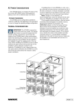
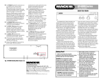
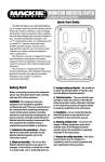
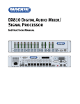
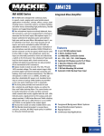
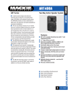
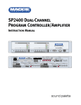
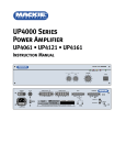
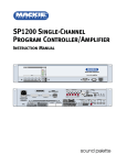
The SP-DSP1 is a
real-time digital
signal processor that
can be installed in
the SP1200 or
SP2400. It uses a
proprietary algorithm
to sense noise in a
room and adjust the
gain of the program
source accordingly.
This unique approach effectively "nulls out"
the music sensed at the ambient microphone,
allowing the DSP to measure the actual
ambient noise level in the room. As the noise
level increases, the gain of the music
automatically increases to compensate for the
increased noise.
U8
U12
U3
U9
U6
U13
DSP
U15
U5
U17
U11
J2
U7
U18 J4
J1
+5V
GND
+5V
U2
J3
U16
U10
TXD
L/R
RXD
GND
+5V
U4
U1
U14
EEPROM
Safety First!
Before installing the SP-DSP card, please
read this Quick-Start Guide carefully and keep
it for future reference.
CAUTION! This circuit board is
static sensitive, and is packed in
an anti-static bag. Please use
anti-static precautions when
handling the SP-DSP card, such as the use of
an electrically grounded wrist band and antistatic mat.
WARNING! These servicing
instructions are for use by
qualified personnel only. To
avoid electric shock, do not
perform any servicing other than that
contained in the Operating Instructions
unless you are qualified to do so. Refer all
servicing to qualified service personnel.
Make sure the power is off and the power cord
disconnected before removing the top cover to
gain access to the inside of the SP2400.
Mackie Industrial strongly recommends that
this circuit board be installed only by a
professional technician, sound installer, or
contractor with electronic servicing experience.
1. Never open the SP1200/SP2400 with the
power supply on.
2. After installing the SP-DSP1 card, and before
applying power to the SP1200/SP2400,
make sure the cover is properly installed
and that no wires are pinched between the
cover and chassis.
Installing the SP-DSP1 Card
Note: These instructions describe how to install one SP-DSP1 into the Zone A side of the SP2400.
A second SP-DSP1 may be installed in the Zone B side. The instructions for Zone B are the same
unless otherwise indicated.
S1
S4
S3
J7
+18
J9
J10
J11
J12
J4
ON
J3
J2
F2
F1
S5
R261
R263
J5
J13
J3
U16
OFF
J8
U14
–18
S2
REAR PANEL
U9
J6
1 2 3 4 5 6 7 8
U12
1 2 3 4 5 6 7 8
U8
U3
ON
P1
ON
R262
SP
S
-D
U10
U13
SP2400 INPUT BOARD
U15
U18 J4
J2
J1
1
3
2
J10
J4
1
R67
1
3
2
3
2
R110
2
C7
C9
J4
1
1
3
J3
J2
C8
C10
C7
C9
C17
C11
1
2
J1
2
2
C4 C5 C6
3
2
R68
3
1
J9
R67
1
3
2
2
JP2
C15
J10
JP1
C18
C15
2
2
J9
3
3
J6
C1 C2 C3
C4 C5 C6
C8
JP2
3
1
1
J3
C10
C17
C18
SP2400 AMP-2 BOARD
JP1
3
2
3
1
J6
C1 C2 C3
3
2
J5
2
3
1
J2
1
1
1
J1
3
J15
J11
C11
R68
J1A
+5V
GND
+5V
TXD
L/R
RXD
GND
+5V
J15
3
2
SP2400 AMP-1 BOARD
1
C62
C62
SP2400 AMP-1 BOARD
J11
U7
R110
U6
J1B
U2
U17
EPROM
U11
J5
U5
DSP
U4
U1
SP2400 AMP-2 BOARD
®
MACKIE DESIGNS. ™
© 2000
C1
J2
055-286-00 REV:__
SP2400:SOFT START
R1
J1
J4
J3
R5
J9
R6
F1
JP1
J6
K1
R4
J13
C2
R2
J8
J5
D2
+
J7
J10
BROWN
4A SB 250V
D1
R3
J11
RISK OF FIRE! REPLACE WITH FUSE AS MARKED
J14
BLUE
J12
C3
SP2400 POWER SUPPLY BOARD
FRONT PANEL
Remove cover.
Install SP-DSP1 Board
1. Remove 12 screws from the top of the
cover using a #2 Phillips-head screwdriver.
These screws are all one size.
4. Using a pair of needlenose pliers,
carefully remove the jumper from J4 pins
10 and 11 on the Filter board (rear of unit,
closest to the bottom).
L7
L6
R132
C92 C93 R148
J9 R147 R142
S2
R146
R145
L9
C91
J6
R96
R97
L3
R121
R149
3
2
1
C94
C95
J10
C96
R134
R131
J11
R127
R128
R129
R137
L5
J8
R143
R133
R136
L10
R150
3. Remove two additional screws on each
side of the unit. These screws are all one
size.
C89
2. Remove the front rack mount brackets and
rear support brackets by removing three
screws per bracket. These screws are all
one size.
SP2400 FILTER BOARD
U25
J4
J5
J3
Note: Remember which screws are used for
the top, brackets, and sides so that you can
properly reinstall the top cover.
Remove Jumper and
Install Ribbon Cable (040-470-00)
5. Install the ribbon cable (040-470-00) onto
J4. Make sure the tab on the connector
lines up with the notch in the socket.
2
6. Snap the square end of the four nylon
standoffs into the four square holes on the
input board. Avoid flexing the circuit board
by supporting the outer edge of the board
while pressing down on the standoffs.
Install Power Supply Expansion
Board
10. Remove two screws from the main Power
Supply board, nearest the front of the unit.
Place the Power Supply Expansion board
so the angle brackets align with the holes
on the power supply. Reinstall the screws
through the holes in the angle brackets
and the main Power Supply board.
REAR PANEL
S1
3
S4
S2
1 2 3 4 5 6 7 8
ON
S5
J8
J9
J10
J11
J12
J4
J13 R146
R145
S1
L5
J8
L7
L3
L2
L6
C91
J6
Q1
1
R149
J10
C94
R263
C95
C96
R131
R127
J11
R128
R129
R97
R96
3
2
R261
J5
S2
C92 C93 R148
J9 R147 R142
R132
L9
R121
R134
L4
J7
R143
C89
R133
R136
R137
L10
R150
1 2 3 4 5 6 7 8
ON
R262
SP2400 INPUT BOARD
STANDOFFS
SP2400 FILTER BOARD
C54
C40
B
J1A
U25
C23
D22
J4
D3
J5
J3
J2
J1
MACKIE DESIGNS. ™
© 2000
R1
J1
J3
J7
J10
J13
R3
C3
J8
C2
R2
J5
D2
+
D1
4A SB 250V
J11
RISK OF FIRE! REPLACE WITH FUSE AS MARKED
J14
BLUE
J12
S1
3
S4
S2
J8
J9
J10
J11
J12
J4
R145
S1
L5
J8
L4
J7
L7
L3
L2
L6
R132
C91
Q1
J6
3
2
1
C54
C40
J13 R146
C92 C93 R148
J9 R147 R142
L9
B
C94
S5
R261
C95
J10
C96
J11
R131
R127
R128
R129
D3
J3
J1A
J4
J5
J2
J1
8. Insert the four 1" screws through the holes
in the top of the DSP board and into the
four standoffs. Use a #1 Phillips-head
screwdriver to secure the screws into the
standoffs.
12. Connect one end of the 3-conductor cable
that came with the SP-DSP1 kit to J2 on
the Power Supply Expansion board.
Connect the other end of the cable to J2
on the DSP board. Route the cable
between the two heatsinks.
Warning: Do not press down while tightening
the screws or you could inadvertently crack
the Input board. Use one hand to support the
Input board from the bottom while tightening
the screw with the other hand.
Connect the COMM PORT
13. Connect the 9-conductor cable that came
with the SP-DSP1 kit to J4 on the LED
board. On the other end of the cable,
connect the 5-wire 5-pin connector to J4
on the Zone A DSP board. Connect the 3wire 5-pin connector to J4 on the Zone B
9. Connect the ribbon cable from J4 on the
Filter board to J1 on the DSP board. Make
sure the tab on the connector lines up
with the notch in the socket.
REAR PANEL
F2
F1
J9
J10
J11
J12
J4
R145
S1
L5
J8
L4
J7
L7
L3
L2
L6
R132
L9
J9 R147 R142
C91
J6
Q1
1
3
2
C94
C54
S5
R261
C95
J10
C96
J1B
J4
U25
C23
TXD
L/R
RXD
GND
+5V
D22
R263
J5
S2
R149
J11
R131
R127
R128
R129
D3
J1A
J2
ZONE B POSITION
C40
J13 R146
C92 C93 R148
U15
J3
J2
J8
U18 J4
J3
+5V
GND
+5V
+18
–18
S2
SP2400 INPUT BOARD
U17
J2
J1
J4
J2
J1
Connect Ribbon Cable to J1
TO POWER SUPPLY
EXPANSION BOARD
S1
DSP
STANDOFFS
SP2400 FILTER BOARD
U7
S4
R97
R96
J5
U6
S3
J3
U11
U2
J7
U16
R121
U13
1 2 3 4 5 6 7 8
R143
R134
R137
U5
C89
R133
R136
U14
EEPROM
U10
U4
U1
ON
U9
L10
R150
U3
1 2 3 4 5 6 7 8
U12
ON
R262
U8
J6
R263
J5
S2
R149
U25
C23
D22
TXD
L/R
RXD
GND
+5V
F1
K1
R4
U15
R6
JP1
J6
J1
+5V
GND
+5V
J9
U18 J4
J4
R96
R97
U17
J2
J1
11. Locate the pair of blue wires exiting the
toroidal transformer that aren’t connected to
anything. Plug the connector on the end of
the blue wires into the two-pin connector
(J1) on the Power Supply Expansion board.
The lip on the connector faces the tab on J1.
SP2400 INPUT BOARD
STANDOFFS
SCREWS
SP2400 FILTER BOARD
U7
C1
R121
U6
BROWN
J3
DSP
U11
U2
J2
ON
U16
1 2 3 4 5 6 7 8
R143
R134
R137
U13
U5
C89
R133
R136
U14
EEPROM
U10
U4
U1
1 2 3 4 5 6 7 8
U9
L10
R150
U3
ON
R262
U12
J2
055-286-00 REV:__
SP2400:SOFT START
R5
REAR PANEL
U8
®
TO POWER
TRANSFORMER
TO DSP BOARD
7. Place the SP-DSP1 circuit board on top of
the four standoffs so the four holes in the
DSP board align with the standoffs. The
large square multi-pin integrated circuit
should be on the right side of the board
when facing the front of the unit. Make
sure the ribbon connector (from step 5) is
sticking straight up so that it clears the
front edge of the DSP board.
TO LED BOARD
3
DSP board (leave disconnected if installing
only one DSP card). Route the cable
between the two heatsinks.
Installing the Software
The SP-DSP1 is designed to run under the
Palm™ OS. The SP-Control™ Palm
application is included on a 3.5" floppy disk,
and it can also be downloaded from the
Mackie Industrial website
(www.mackieindustrial.com).
Copy the "SP-Control.prc" file from the
floppy disk to the hard drive on your computer
where the Palm Desktop Application is
installed. Double-click on the "SP-Control.prc"
file, and the "Install Tool" dialog box opens to
let you know that the file will be installed on
your handheld Palm the next time you
perform a HotSync operation.
TO DSP BOARD
TO CPU BOARDS
J4
LED BOARD
FRONT PANEL
Reinstall the Top Cover
14. When placing the top cover back onto the
chassis, be sure all the wiring is properly
routed between and beside the heatsinks
to avoid pinching the wires between cover
and chassis. Replace the screws in the
same order in which they were removed.
Using the SP-Control Application
Once the "SP-Control.prc" file has been
installed on the Palm, you can connect the
Palm to the COMM PORT on the SP2400. Use
the supplied 9-pin “null-modem” adapter
between the Palm’s HotSync cable and the
SP2400’s COMM PORT. This switches pins 2
and 3 (RXD and TXD) on the RS-232
connection so the two devices can
communicate properly.
Select the "SP-Control" application on the
Palm to launch it, and the main SP-Control
window appears on the screen. Click the
“Connect” box to begin communication
between the application and the SP-DSP1.
There are six user-adjustable parameters and
four bar graphs indicating relevant levels.
Using the SP-DSP1 Card
It is important to understand that the
SP-DSP1 does not add gain to the signal path,
but rather attenuates the signal at its input by
a user-adjustable amount, and then applies
less attenuation to the signal to achieve an
increase in volume as determined by the
Ambient Noise Sensing Algorithm.
The default Minimum Gain setting is –40 dB,
so the signal level is 40 dB lower with the
SP-DSP1 card installed than it is without the
card installed (or with the circuit bypassed).
At first, you may wonder why the signal level is
so low when you first turn on the SP2400
because of this additional attenuation.
However, after the parameters are properly
adjusted and you run the Auto Calibration
procedure, the SP2400 will operate with
sufficient volume.
Note: The SP-DSP1 requires connecting a
microphone to the AMBIENT MIC connection
on the rear panel of the SP2400. We
recommend using the Mackie Industrial
MT-3100 omnidirectional condenser
microphone. However, if the installer
determines that a directional microphone is
better suited to the application, such as the
Mackie Industrial MT-3200 semi-cardioid
condenser microphone, it may be used as well.
Be sure to move the AMP ADDRESS switch
#8 up to activate the ambient microphone.
4
Adjustable Parameters
parameter defines the time it takes for the
Program Gain to decrease by 40 dB. These
parameters have a maximum value of 300
seconds (5 minutes). A short Attack Time
allows the program level to respond to every
shift in noise level. Increasing the Attack Time
allows the algorithm to “average” the noise
level and provide a relatively constant
Program Gain over time. To keep impulsive
bursts of noise from affecting the program
level, a good setting might be Attack = 20
seconds and Release = 20 seconds.
MG (Minimum Gain)
This control defines the lowest level to
which the system can attenuate the program
signal. It has a minimum setting of –40 dB
and a maximum setting of 0 dB.
GR (Gain Range)
This control defines the amount of gain
change allowed by the Automatic Level Control.
It has a minimum setting of 0 dB and a maximum setting of 40 dB. The Gain Range setting
can never be greater than the Minimum Gain
setting, because the system gain from the
input to the output of the SP-DSP can never be
greater than 0 dB. Because of this, the Gain
Range control “re-scales” itself if the Minimum Gain control is increased toward 0 dB.
As an example of how these controls work
together, if the user wanted his music levels
to operate in a range ±10 dB around –15 dB
down from the input level, he would set
MG = –25 dB and GR = 20 dB.
Bar Graphs/Metering
PI (Program Input)
This indicates the input level into the DSP.
It is important that the Program Input signal
level is sufficient prior to running the Auto
Calibration procedure. The input level should
be between 0 and –10 dB during the loudest
portions of the program material. Adjust the
level with the front panel up/down buttons.
MI (Microphone Input)
This indicates the ambient microphone
input level into the DSP. Again, it is important
that the ambient microphone signal level is
sufficient prior to running the Auto Calibration
procedure. The input level should be between
0 and –10 dB for the loudest noise plus
program expected.
It may be necessary to adjust the gain of
the ambient microphone. A good way to set
the MI level is to click the “Bypass” box on the
main screen. You may need to turn down the
program level if there is a lot of attenuation
set with the Minimum Gain (MG) control, or the
music will become very loud in bypass mode.
There is a trim pot located through an unmarked hole just above the AMBIENT MIC
connector on the rear panel of the SP2400.
Use a nonconductive alignment tool to adjust
the pot until the meter indication is between
0 and –10 dB for the loudest noise plus
program expected.
NT (Noise Threshold)
This control sets the point at which the
noise level “triggers” the Automatic Level
Control to begin working. It has a minimum
setting of –80 dB and a maximum setting of 0
dB. The lower the Noise Threshold setting, the
more sensitive the algorithm is to ambient
noise levels in the room.
NR (Noise Range)
This control adjusts the ratio of how much
the program level changes as a function of
how much the noise level changes. It has a
minimum setting of 1 dB and a maximum
setting of 60 dB.
For example, if you set the Noise Range to
20 dB and the Gain Range to 30 dB, then a 20
dB change in the noise level causes a 30 dB
change in the program output level (assuming
the noise level has crossed the Noise
Threshold). These settings represent a 2:3
noise level to program level change. For every
2 dB change in noise level, the output level
changes by 3 dB. However, if you accept the
default settings of NR = 40 dB and GR = 40
dB, the settings represent a 1:1 noise level to
program level change. For every 1 dB change
in noise level, the output level changes by 1 dB.
PG (Program Gain)
This indicates the amount of gain the algorithm applies to the program input. This can
never exceed the Minimum Gain (MG) setting.
PO (Program Output)
This indicates the output level from the
SP-DSP1. The Program Output is equal to the
Program Input (PI) level plus the Program
Gain (PG).
Attack Time and Release Time
The Attack parameter defines the time, in
seconds, it takes for the Program Gain to
increase by 40 dB. Likewise, the Release
5
have a CAL value closer to 0 dBr, indicating a
lower rejection due to room reflections.
Any of the user parameters can be adjusted
after the Auto Calibration procedure is
completed (MG, GR, NT, NR, Attack Time,
Release Time). These settings do not affect
the calibration of the SP-DSP1. However, if the
placement of the ambient microphone or
speakers should change for any reason, you
should run the Auto Calibration procedure
again to allow the SP-DSP1 to reevaluate the
room transfer function.
Likewise, if any level
changes are made in the
signal chain after the SP-DSP1
card, the noise sensor
perceives this as an acoustic
noise disturbance, and the
Auto Calibration procedure
should be performed again.
Note that all the level
controls in the SP2400 are
before the SP-DSP1 and have
no effect on the calibration.
Additional Main Screen Options
Preset Save/Recall
The SP-Control has the ability to save up to
10 presets in the SP-DSP1 EEPROM. A preset
consists of the following parameters:
Minimum Gain (MG), Gain Range (GR), Noise
Threshold (NT), Noise Range (NR), Attack Time,
and Release Time.
To save or recall a preset, click the arrow
next to the Preset button to select which
preset number to save, then click the Preset
Save or Preset Recall button.
DSP1/2
The SP2400 can support
two SP-DSP1 cards; one for
each zone. Click this button
to toggle control between
DSP1 and DSP2.
Auto Calibration Function
Click on the "SP-Control"
button at the top of the main
screen and a drop-down
menu appears. Select "Auto
Calibration" to begin the Auto Calibration
procedure. This should be performed once the
ambient microphone and the loudspeakers
are in their fixed positions, and the
microphone gain and input levels have been
properly adjusted. For best results, the Auto
Calibration procedure should be performed
when the room noise is at a minimum.
During the calibration, a countdown timer is
initiated at 90 seconds and a progress meter is
displayed. If the algorithm finds that adaptation
improvements are possible, the timer resets to
90 seconds. A typical calibration period is 2-3
minutes. It is advised to monitor the main four
meter levels during calibration to ensure that all
levels are in their target range. If you find that the
microphone and input levels are too low or too
high, you may want to "Abort" the calibration by
selecting the appropriate button and then
readjust the levels accordingly. There is also an
“End & Save” button if the user finds that
calibration is taking too long or music breaks are
causing countdown timer resets.
Once the calibration is complete, the CAL
value will update. At default, this value is +10
(with a range of +20 to –80 dBr). This number
is a measure of how much of the program
material is getting rejected in the environment
that the Auto Calibration was performed. The
closer the number is to +10, the less the
rejection. A CAL value = –15 dBr would be an
excellent rejection value, which would be
expected in a small room. A larger room would
Factory Restore
Select Factory Restore from the drop-down
menu to restore all the settings in the SPDSP1 to their default values.
Upload/Download From/To EEPROM
Occasionally, it is necessary to backup
SP-DSP1 presets and parameters or to transfer
settings from one DSP to another. To copy the
contents of the EEPROM, simply select
“Upload from EEPROM” from the drop-down
menu. The EEPROM contents are stored in
your Palm. If you would like to copy contents
of the Palm into another SP-DSP1 card, select
“Download to EEPROM.” This will completely
erase the existing contents of the EEPROM
and replace it with what was stored in the
Palm. It is advised that you do an “Upload
from EEPROM” before doing a “Download to
EEPROM” to ensure that the current settings
are saved in the Palm.
[email protected]
www.mackieindustrial.com
16220 Wood-Red Road NE Woodinville, WA 98072
TEL +888.337.7404, FAX +425.487.4337
UK +44.1268.570.808, FAX +44.1268.570.809 [email protected]
ITALY +39.0522.354.111, FAX +39.0522.332.294 [email protected]
FRANCE +33.3.8546.9160, FAX +33.3.8546.9161 [email protected]
GERMANY +49.2572.96042.0, FAX +49.2572.96042.10 [email protected]
Part No. 910-300-20 Rev. A 12/00
© 2000 Mackie Industrial. All Rights Reserved. Printed in the USA.
6