1
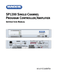
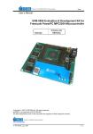
Button Section
The Button Section includes the assignment
buttons (Audio In, Logic In, Logic Out, Groups, Input
Proc, Out Proc, Mute Ind) and the DSP buttons
(Input EQ, Graph EQ, Param EQ, Compress, Gate,
Delay, X-Over).
Assignments
Audio In
Click this button to open the Audio Input window.
Name: Enter a name for each channel with the
keyboard. It will accept up to 32 characters.
Force On: Assign a force-on level to each input,
from OFF to +10 dB. Click and drag in the Force On
Level box to change the force-on level setting. The
force-on action is always relative to the current
mix level.
DX810 – 22
Force Off: Assign a force-off level to each input,
from OFF to +10 dB. Click and drag in the Force Off
Level box to change the force-off level setting. The
force-off action is always relative to the current mix
level.
Force On Priority: Assign a priority level from 1
(highest) to 8 (lowest) for each channel’s force-on
function. The default setting is None.
Logic In
Click this button to open the Logic Input window.
Make the following settings and assignments in the
Logic Input window:
Name: Enter a name for each Logic Input, up to
32 characters.
Function: Select one of 7 different functions in
this drop-down box. The functions include Inactive,
Force-on, Force-off, Mute Input, Mute Output, Mute
Group, and Preset Recall.
Action: Select whether the particular function
selected is momentary, latch on, latch off, or
toggling. The selections will vary depending on the
function selected for the Logic Input.
Affected I/O: Select which Input or Output is
affected by the Logic function. The selections will
vary depending on the function and action selected
for the Logic Input.
See Appendix A for a chart of the Logic Input
functional combinations available.
Logic Out
Click this button to open the Logic Output
window. Make the following settings and
assignments in the Logic Output window:
Name: Enter a name for each Logic Output, up to
32 characters.
Function: Select one of 5 different functions in
this drop-down box. These functions include
Inactive, Input Signal Present, Output Signal Present,
Preset Active, and Priority Inactive.
Parameter: Select the input, output, or other
parameter that is being monitored by the Logic
Output. The selections will vary depending on the
function selected for the Logic Output.
Condition: Displays the particular condition that
must be satisfied for the Logic Output to become
active. The condition will vary depending on the
function and parameter selected for the
Logic Output.
See Appendix B for a chart of the Logic Output
functional combinations available.
Groups
Click this button to view group assignments for
crosspoints and outputs. The gain readout boxes
change to a blue background and display the
assigned group for the crosspoint or output. This is
true of the Crosspoint Matrix and Output Sections.
DX810 – 23
Input Proc
Click this button to view the processors (Gate,
Compressor, Input EQ) that are active for each input
in the Crosspoint Matrix Section. Lit buttons show
processors that are turned on. Click the buttons to
turn the processors on and off for each
individual input.
Mute Ind
Click this button to view the Active Mute Groups
indicator in the upper left corner of the screen. If a
group mute button is active, the associated
indicator lights up in the Active Mute Group indicator.
DSP
Input EQ
Click this button to view the Input 3-band EQ
controls, superimposed over the Crosspoint
Matrix Section.
Out Proc
Click this button to view the processors that are
active for each output in the Crosspoint Matrix
Section. These processors include Graphic EQ,
Parametric EQ, X-Over, Delay, and Compressor. Lit
buttons show processors that are turned on. Click
the buttons to turn processors on and off for each
individual output.
Each input strip has a 3-band EQ comprised of:
1. A high-frequency shelving EQ with adjustable gain
(±15 dB) and frequency (500 Hz–20 kHz).
2. A mid-frequency parametric EQ with adjustable
gain (±15 dB), frequency (20 Hz–20 kHz), and
bandwidth (0.1–6.0 octaves).
3. A low-frequency shelving EQ with adjustable gain
(±15 dB) and frequency (20 Hz–500 Hz).
4. An ON button to turn the EQ on and off.
Click and drag up and down on the control knob
to change the setting. Note: You can not directly
enter a numeric value with the mouse and
keyboard. Note that the EQ settings apply to all the
outputs to which the input is assigned.
Use the arrow keys on the keyboard to make
fine adjustments to a selected control, and the Page
Up/Down keys to make course adjustments. Use
the Tab key to quickly move the selection to
adjacent controls.
Note that if two or more outputs are linked via
the Crossover window, only one button appears.
This is true of the Graphic EQ, Parametric EQ, and
X-Over output processors, as shown in outputs A, B,
and C above.
DX810 – 24
Graph EQ
Click this button to view the 31-band 1/3-octave
Graphic EQ controls for a selected output. Click the
output letter buttons (A-J) to select an output.
Click the On button to activate the Graphic EQ
for the selected output. The Reset button returns all
the sliders to their center (0 dB) positions.
Each band is on an ISO center frequency ranging
from 20 Hz to 20 kHz, with ± 15 dB gain on
each band.
Click and drag on a slider knob to adjust the EQ.
Use the arrow keys on the keyboard to make fine
adjustments to a selected control. Use the Page
Up/Down keys to make course adjustments. The
selected band’s GAIN and BAND (frequency) are
displayed at the top of the window.
Click the right mouse button over the processor
display. This brings up a menu allowing you to cut,
copy, or paste the processor settings to
another output.
Param EQ
Click this button to view the 5-band Parametric
EQ controls for a selected output. Click the output
letter buttons (A-J) to select an output.
Click the On button to activate the Parametric
EQ for the selected output. The Reset button
returns all the controls to their center positions.
Each band has adjustable gain (± 15 dB),
frequency (20 Hz–20 kHz), and bandwidth
(0.1–6.0 octaves).
Click the right mouse button over the processor
display. This brings up a menu allowing you to cut,
copy, or paste the processor settings to
another output.
Compress
Click this button to view the Compressor for a
selected input or output. Click an input SELECT
button to select an input. Then click the output
letter buttons (A-J) to select an output.
Click the On button to activate the Compressor
for the selected input or output. The Reset button
returns all the controls to their default positions.
The Compressor has five knobs: Attack, Release,
Output, Threshold, and Ratio. Click and drag on the
individual knobs to adjust each parameter. An
analog-style meter indicates the amount of
compression applied in decibels.
Click the right mouse button over the processor
display. This brings up a menu allowing you to cut,
copy, or paste the processor settings to
another channel.
About Compression:
A compressor is used to reduce or limit transient
peaks in a signal. As the input level to the
compressor increases, the output level increases
linearly until the threshold point is reached. After
that point, the output level no longer increases
linearly. Instead, it increases at a reduced rate
determined by the ratio setting.
This compressor features ‘soft-knee’
compression. The input signal level approaches and
crosses the threshold. Simultaneously, the
compressor gradually starts compressing. This
increases the ratio to the required setting smoothly.
• Threshold: This control determines the level around
which the compressor begins to act on the incoming signal. It is calibrated in decibels, with a range
from –60.0 dBFS to –1.0 dBFS.
• Attack: This determines how fast the compressor
reacts once the threshold has been exceeded. It is
calibrated in milliseconds, with a range from
0.1 ms to 2500 ms (2.5 seconds) per 20 dB of gain
change.
• Release: This determines how fast the compressor
turns off once the signal falls below the threshold.
It is calibrated in milliseconds, with a range from 10
ms to 2500 ms (2.5 seconds) per 20 dB of gain
change.
• Ratio: This determines the change in output level. It
is a function of the change in input level (at full
compression), once the threshold has been fully
exceeded. It is calibrated in decibels, with a range
DX810 – 25
from 1.0:1 (off) to 20:1. Thus, if it is set to 10:1, an
increase in input level of 10 dB results in a 1 dB
increase in output level. This assumes the input is
above the threshold level.
Generally, use ratio settings from 1.5:1 to 5.0:1 for compressor
use. Settings from 10:1 to 20:1 are more useful for limiting
purposes. This is because in that range the output level changes
very little as the input increases.
•
Output: This determines the overall gain of the compressor from
input to output (as measured with the signal below the threshold
level). You can use this control to compensate for the loss of gain
caused by the action of the compressor. It is calibrated in
decibels, with a range from 0 dB (unity) to +20.0 dB.
Gate
Click this button to view the Gate for a selected
input. Click an input SELECT button to select
an input.
Click the On button to activate the Gate for the
selected input. The Reset button returns all the
knobs to their default settings.
The Gate has four knobs: Hold, Release,
Threshold, and Range. Click and drag on the
individual knobs to adjust each parameter. An
analog-style meter indicates the input signal level
for the selected channel.
Click the right mouse button over the processor
DX810 – 26
display to bring up a menu that allows you to cut,
copy, or paste the processor settings to
another channel.
About Gating:
A gate is used to duck or mute a channel when the
signal level drops below a certain point. This can
reduce the overall noise level in your mix by muting
unused or noisy channels.
Note: When we say the gate opens, it means the
gate is not acting on the signal and the signal is
allowed to pass. When the gate closes, the gate
acts on the signal by attenuating it.
• Threshold: This determines the level below which the gate
closes (and above which it opens). It is calibrated in decibels,
ranging from –60 dBFS to –1 dBFS.
•
Hold: This determines how long the gate remains open after the
input signal has fallen below, and remains below, the threshold
before closing. It is calibrated in milliseconds, ranging from 0 ms
to 2550 ms (2.55 sec).
•
Release: This determines how fast the gate closes after the hold
time has expired. It is calibrated in milliseconds, ranging from 10 ms
to 2500 ms (2.5 sec) per 20 dB of gain change.
•
Range: This determines the amount of attenuation of the input
signal when the gate is closed. It is calibrated in decibels, ranging
from –100 dB to –1 dB.
Delay
Click this button to view the Delay settings for a
selected output. Click the output letter buttons (A-J)
to select an output.
Click the On button to activate the Delay Line.
Click the Metric button to change the settings from
inches/feet/Fahrenheit to mm/meters/Celsius. Click
the Reset button to return all the knobs to their
default settings.
The Delay Line has three knobs: Temp, Coarse,
and Fine. Click and drag on the individual knobs to
adjust each parameter.
Temp: The speed of sound varies with air
temperature. Therefore it is necessary to enter the
ambient air temperature. This is in order to
accurately calculate the time delay required as a
function of distance traveled. This control is
calibrated in degrees, ranging from –40°F to 122°F
(–40°C to 50°C).
Coarse: This control adjusts the delay in 1
millisecond increments, with a range from 0 ms to
200 ms. The equivalent distance the sound travels
in the selected amount of time is displayed. Use
this control when setting up a delay between two
speakers, as in a delay tower.
Fine: This control adjusts the delay in small
increments (22.7 µs), with a range from 0 µs to 997
µs. The equivalent distance the sound travels in the
selected amount of time is displayed. Use this
control to adjust for offsets between drivers in a
stack. For example, use this control to time-align a
horn’s compression driver and a woofer’s voice coil.
Click the right mouse button over the processor
display. This brings up a menu allowing you to cut,
copy, or paste the processor settings to
another channel.
X-Over
Click this button to view the 1 to 5-Band
Crossover. The crossover window has a graphic
display to indicate the number of bands and
crossover points selected. Up to five outputs can be
selected, which become linked to a single row of
inputs. In other words, each of the eight inputs has
just one mix level to the combined outputs in the
crossover. This is reflected in the Crosspoint Matrix
Section by “blanking out” all but the top row of
crosspoints for the linked crossover outputs. Note
that only contiguous outputs may be linked to
create a crossover.
Linking outputs together for the crossover
automatically links those outputs in the Parametric
EQ and the Graphic EQ processors.
The equalizers are located prior to the crossover
in the signal chain, so all the outputs assigned to
the crossover are affected by the EQ settings.
With the first band active (red active button lit),
click the On button to turn the crossover on and off.
When the crossover is turned off, all the outputs
assigned to the crossover pass a full-range signal.
Click the Reset button to return all the knobs for the
currently active band to their default settings.
Output: Select the first output for the crossover
(A-J). It appears in the first Output box. Click the
arrow next to the box to select an output in the
pull-down list.
Polarity: The Polarity button reverses the polarity
of the output by 180°.
Edit: Click the Active button under Edit to adjust
the settings for the selected output. Then use the
Frequency, Filter Slope, Alignment, and Filter
Type controls.
Filter Type: Use this control to select high-pass
(HP), low-pass (LP), or band-pass (BP) filters for the
selected output. Notice that the Frequency control
selection changes to High Freq and Low Freq when
BP is selected.
Alignment: This switch selects either LinkwitzRiley (L) or Butterworth (B) characteristics for the
selected Filter Type.
Filter Slope: Use this control to choose the rolloff curve for the frequencies above or below the
cutoff frequency. When Butterworth alignment is
selected, 12, 18, and 24 dB/octave slopes are
available. When Linkwitz-Riley is selected, 12 and
24 dB/octave are available.
Frequency: This selects the cutoff frequency for
the selected filter, with a range from 20 Hz to 20
kHz. When a bandpass filter is selected, High Freq
and Low Freq controls are available.
Option
This button is reserved for future upgrades.
DX810 – 27
Crosspoint Matrix Section
This section provides a view of all the input-tooutput crosspoints in the mixing matrix. It has a
numerical and graphical indication of the gain setting
for each crosspoint.
Click the associated letter button (A-J) in the
Output Section to select an output and the
horizontal row of input crosspoints is highlighted.
The input faders in the Input Section now control
the gain settings and mix for the selected output.
Either click on the fader or click on the horizontal
mini-fader indicator bar in the crosspoint to adjust
the gain for the input.
Click the select (S) button to select the
crosspoint for copying or pasting the level.
Otherwise, when a group is selected, use it to
assign the crosspoint to the selected group.
Input Section
This section includes the eight input faders along
with their associated bargraph input level meters;
Select, and Mute buttons; and name box.
DX810 – 28
The fader adjusts the mix level from the input to
the output selected in the Crosspoint Matrix
Section (indicated by the highlighted row). The
numerical display for the level is shown at the
crosspoint in the Crosspoint Matrix section. Use
the arrow keys on the keyboard to make fine
adjustments to the level. Use the Page Up/Down
keys to make course adjustments.
The input level meter indicates the level of the
input signal as it comes out of the analog to digital
converters and shows the level in dBFS. If the red
0 dB portion is lit, then the signal level is above –
2 dBFS and may be clipped. Note that the meter
indicates the signal level before any processing or
digital gain stages. If the signal is clipping, or is too
low, adjust the signal level at the source, or use the
trim pots on the rear panel of the DX810.
Click the SELECT button when a group is
selected to assign the input to the selected group.
The assigned group fader then affects the signal
level for that input to all ten outputs. Click the
SELECT button when the gate or compressor
windows are showing to adjust the processing
options for that input.
Click the MUTE button to mute the input signal to
all ten outputs.
Use the name box at the bottom of the Input
Section to enter a name for the input (e.g., CD Left,
CD Right, Vocal, Guitar, etc.), up to 32 characters.
Output Section
The Output Section includes the ten output
faders along with their associated bargraph output
level meters. This section also includes numerical
gain display, mute and solo buttons, and name box.
Use the output faders to adjust the final output
level of the signal. Adjust the output faders so that
the associated output meter indicates around the
–10 and –7 dB positions when a normal signal is
going to that output. This provides the best signalto-noise ratio for the output stage. It’s okay for the
–4 and –2 LEDs to blink occasionally on musical
peaks. However, avoid allowing the red 0 dB
indicator to light, which indicates that the signal is
within 2 dB of clipping.
Note that the meter indicates the signal level
after the output signal processing (i.e., Graphic EQ,
Parametric EQ, Compressor, Crossover). If
adjustments are made to the output processors, the
output fader may need to be readjusted. This is to
compensate for an increase or decrease in gain
through the processors.
Click the (M) button to mute the output signal.
Click the (S) button to solo the output. This
mutes all the outputs except the soloed output.
This is useful for troubleshooting and listening to
each output individually.
Click the letter button (A-J) when a group is
selected to assign the output to the selected group.
Click the letter button when a processing window is
showing (except Gate and Input EQ) to adjust the
processing options for that output.
Use the box to the right of the Output Section to
enter a name for the output (e.g. Main Left, Control
R), using up to 32 characters.
Group Section
This section includes the 32 control groups.
Eight groups are displayed at one time. However,
the horizontal fader at the bottom allows you to
scroll through all the control groups.
To assign or unassign a crosspoint or output to
a group:
1. Click the select (S) button for the desired group. If any
crosspoints or outputs are assigned to the selected group, their
select buttons light.
2. Click the select (S) button for the crosspoints you want to assign
to the selected group. The group fader affects the mix level for
each crosspoint to a single output.
3. Click the SELECT button in the Input Section to assign the input
fader to the selected group. The group fader affects the mix level
for each input to all the outputs.
4. Click the associated letter button (A-J) in the Output Section to
assign an output to the selected group. The group fader affects a
single output level.
5. Click the Groups button in the Top Section to view and verify
group assignments.
Group assignments are saved in each preset.
This allows different combinations of crosspoints,
inputs, and outputs to be assigned to the same
group number in separate presets. This is useful for
room combining applications.
Click the (M) button to mute the group. This
mutes all crosspoint, inputs, and outputs assigned
to the group. Click the Mute Ind button to view the
Active Mute Groups indicator.
The group fader controls the relative level for all
the crosspoints, inputs, and outputs assigned to it.
At the unity gain position (U), all the levels are at
their assigned values and the group fader has no
effect. Reduce the group fader 10 dB, and all the
levels assigned to that group are reduced 10 dB,
relative to their assigned value. Note that the group
fader can increase the level 10 dB. However, if an
assigned level is already at +10 dB, it will not
change. The maximum overall gain available for any
crosspoint, input, or output is +10 dB.
Use the box at the bottom of the Group Section
to enter a name for the group (e.g., Voc, Drum),
using up to 32 characters.
There is a mute and select button associated
with each Control Group.
DX810 – 29
DX810 – 30
LINE
CHANNEL 1
MIC
+48 VDC
PC
OR OTHER
CONTROL
DEVICE
(OPTIONAL)
LOGIC
IN
(1 OF 10)
DIRECT
OUTPUT
PHANTOM POWER
+5V
FRONT PANEL
COMM PORT
TRIM
ADC
24-BIT
CONTROL
PROCESSING
GATE
32-BIT DSP
INPUT METER
COMPRESSOR
REMOTE
CONTROL
REAR PANEL
COMM PORT
+5V
CHANNELS 2-8
(IDENTICAL TO CH 1)
3-BAND INPUT EQ
REMOTE
CONTROL
(OPTIONAL)
TO ADDITIONAL
REMOTE CONTROLS
(OPTIONAL)
D
C
B
A
MUTE
MUTE
MUTE
MUTE
BUS B
INPUT
BUS A
INPUT
31-BAND GRAPHIC EQ
31-BAND GRAPHIC EQ
31-BAND GRAPHIC EQ
31-BAND GRAPHIC EQ
BUSES E-J
(IDENTICAL TO A-D)
DELAY
DELAY
DELAY
DELAY
5-BAND PARAMETRIC EQ
5-BAND PARAMETRIC EQ
5-BAND PARAMETRIC EQ
5-BAND PARAMETRIC EQ
TRIM
TRIM
X-OVER
X-OVER
X-OVER
X-OVER
COMPRESSOR
OUTPUT METER
COMPRESSOR
OUTPUT METER
COMPRESSOR
OUTPUT METER
COMPRESSOR
OUTPUT METER
DAC
24-BIT
DAC
24-BIT
DAC
24-BIT
DAC
24-BIT
INTERNAL ANALOG
BUSES
A B C D E F G H I J
A
B
MACKIE INDUSTRIAL
DX8 w/DX•10e Installed
BLOCK DIAGRAM
(#9/24/01 DF)
DX810 Block Diagram
REMOTE
CONTROL
(OPTIONAL)
PC
OR OTHER
CONTROL
DEVICE
(OPTIONAL)
LOGIC
OUT
(1 OF 10)
MUTE
INTERNAL DIGITAL
BUSES
A B C D E F G H I J
A
OUTPUT
–
+
G
–
+
G
–
+
G
–
+
G
–
+
G
–
+
G
–
+
G
–
+
G
–
+
G
G-J
OUTPUTS
C-F
OUTPUTS
B
OUTPUT
RECORD
OUTPUTS
–
+
G
6. SPECIFICATIONS
DX810 Specifications
SIGNAL PROCESSING
INPUTS / OUTPUTS
Inputs 1-8:
Balanced, Phoenix-type terminals
Bus A and B:
Balanced, Phoenix-type terminals, Direct to
Mix Buses
Outputs A-J:
Balanced, Phoenix-type terminals
Record Outputs A/B:
Unbalanced, RCA
Direct Outputs 1-10:
Unbalanced on DB15
(bottom row is signal return)
Logic Inputs:
10 Inputs on DB25
Series resistance: 570Ω
Internal pull-up: 47 kΩ to +5 VDC
Input voltage:
+5.5 VDC maximum
Active voltage: +1.0 VDC maximum
Logic Outputs:
Serial Ports:
10 open-collector Outputs on DB25
Series resistance: 550 Ω
Internal pull-up: 10 kΩ to +5 VDC
Active current:
10 mA maximum
Active voltage: +0.8 VDC max @ 1 mA
General:
Five 32-bit floating-point DSPs
24-bit A/D and D/A converters
512Kx16 Flash ROM
128Kx32 SRAM (with battery backup)
Inputs:
3-band shelving EQ with parametric mid
Gain: ±15 dB
Corner Frequency:
LO: 20 Hz-500 Hz variable
HI: 500 Hz-20 kHz variable
Center Frequency:
MID: 20 Hz-20 kHz variable
Gate on each Input
Threshold: –60 dBFS to –1 dBFS
Hold:
0 ms to 2500 ms
Release: 10 ms to 2500 ms
Range:
–100 dB to –1 dB
Outputs:
2 RS-232C on DB9 (COMM PORTS)
Crossover
Polarity: 0º, 180º
Filter Type: High-Pass, Low-Pass,
Band-Pass
Alignment: Linkwitz-Riley,
Butterworth
Filter Slope: 12 dB/oct, 18 dB/oct,
24 dB/oct (Butterworth only)
Frequency: 20 Hz-20 kHz
PANEL CONTROLS
Input Trim:
8 Rotary Potentiometers
Input Gain:
2 Pushbuttons per Input
EQ:
2 Pushbuttons for Low, 2 for High
Master Output Gain:
2 Pushbuttons per Output
Mode Select:
1 Pushbutton
Power:
Rocker Switch
1/3-Octave Graphic EQ on each Output
Gain: ±15 dB
ISO-Centered Frequencies: 20, 25,
31.5, 40, 50, 63, 80, 100, 125, 160,
200, 250, 315, 400, 500, 630, 800, 1 k,
1.25 k, 1.6 k, 2 k, 2.5 k, 3.15 k, 4 k,
5 k, 6.3 k, 8 k, 10 k, 12.5 k, 16 k, 20 k
Phantom Power Select: 8 DIP Switches
PANEL INDICATORS
Input Levels:
12-segment LEDs per ch.
Output EQ Levels:
12-segment LEDs per ch.
Mode Status:
3 LEDs; A/B/LOCK
Output Levels:
12-segment LEDs per ch.
Volume Setting:
12-segment LED Bar Graph
5-Band Parametric EQ on each Output
Gain: ±15 dB
Center Frequency:
20 Hz-20 kHz variable
Bandwidth: 0.1 octave to 6 octaves
Compressor/Limiter on each Input and Output
Threshold: –60.0 dB to –1.0 dB
Attack: 1 ms to 2500 ms
Release: 10 ms to 2500 ms
Ratio: 1:1 to 20:1
Output: 0 dB to +20.0 dB
LED METER VALUES
1.
2.
3.
4.
5.
6.
7.
8.
9.
10.
11.
12.
Red (scale: OL):
Yellow (scale: 2):
Yellow (scale: 4):
Yellow (scale: 7):
Green (scale: 10):
Green (scale: 15):
Green (scale: 20):
Green (scale: 25):
Green (scale: 30):
Green (scale: 35):
Green (scale: 40):
Green (scale: 50):
>
>
>
>
>
>
>
>
>
>
>
>
–2 dB full-scale (> 16 dBu)
–4 dB full-scale (> 14 dBu)
–7 dB full-scale (> 11 dBu)
–10 dB full-scale (> 8 dBu)
–15 dB full-scale (> 3 dBu)
–20 dB full-scale (> –2 dBu)
–25 dB full-scale (> –7 dBu)
–30 dB full-scale (> –12 dBu)
–35 dB full-scale (> –17 dBu)
–40 dB full-scale (> –22 dBu)
–50 dB full-scale (> –32 dBu)
–60 dB full-scale (> –42 dBu)
Delay on each Output
Temp:
–40ºF to 122ºF
(40ºC to 50ºC)
Coarse:
0 ms to 200 ms
Fine:
0 µs to 997 µs
Audio
Noise
(20 Hz-20 kHz bandwidth, Master Out, channel Trims @ unity gain,
channel EQs flat, all odd channels panned left, even channels
panned right):
Master level @ unity, channel levels @ unity: –82 dBu
Single channel to Master Out:
–100 dBu
(referenced to 1% THD+N)
DX810 – 31
Total Harmonic Distortion (THD+N)
(1 kHz @ +10 dBu (unity level) 20 Hz-20 kHz):
Mic in to Master Out:
< 0.005%
PHYSICAL
Dimensions (HxWxD):
3.5"/2 RU (89mm) x 19" (483mm) x
13.25" (337mm)
Crosstalk
(1 kHz relative to 0 dBu, 20 Hz-20 kHz bandwidth, any line input to
adjacent Direct Out):
Trim to unity:
< –90 dB
Net Weight:
12.9 lbs. (5.9 kg)
Frequency Response
Mic input to any output:
AC Power:
90–240 VAC, 50/60 Hz, 1.0 A
DC Power:
24 VDC, 3 A
Phantom Power:
+48 VDC, current limited to 7 mA
per input channel
Common Mode Rejection (CMR)
Mic in to Direct out, max gain, 1 kHz signal:better than 80 dB
Fuse Ratings:
1.6 A Slo Blo, 250 V
Maximum and Nominal Levels and Ranges
Mic inputs:
+18 dBu, +4 dBu,
0 to 60 dB gain
PC SYSTEM REQUIREMENTS
20 Hz–20 kHz, ±0.5 dB
Equivalent Input Noise (EIN)
Mic in to Direct out, max gain, 150 ohm termination:
–129.5 dBm unweighted
Line inputs:
+18 dBu, +4 dBu,
–30 to +30 dB gain
ELECTRICAL
OS:
Windows® 95, 98 or NT®
Processor:
Pentium® or faster
RAM:
16 MB minimum
32 MB recommended
Bus A/B inputs:
+18 dBu, +4 dBu,
–20 to +20 dB gain
Storage:
10 MB free disk space
All outputs:
+18 dBu, +4 dBu
Display:
800x600 pixels, 256 colors minimum
Impedances
Mic inputs:
Line inputs:
All other inputs:
All outputs:
1.3K ohms
40K ohms
10K ohms or greater
120 ohms
DX-810
DX810 – 32
Disclaimer
7. Service Information
Mackie Industrial continually engages in research
related to product improvement, new materials, and
production methods. Design refinements are
introduced into existing products without notice as
a routine expression of that philosophy. For this
reason, any current Mackie Industrial product may
differ in some respect from its published
description, but will always equal or exceed the
original design specifications unless otherwise
stated.
Mackie Industrial is a trademark or registered
trademark of Mackie Designs Inc.
All other brand names mentioned are trademarks
or registered trademarks of their respective holders,
and are hereby acknowledged.
In the event that your DX810 should require
servicing, please follow these instructions:
© 2002 All Rights Reserved.
Mackie Industrial.
1. Call Mackie Industrial Tech Support at 1-888-3377404, 8 am to 5 pm PST (Monday-Friday). Verify
the problem and obtain a Return Authorization
(RA) Number. Be sure to have the serial number of
the unit when you call. You must have a Return
Authorization Number in order to obtain warranty
service at the factory or at an authorized service
center.
2. Pack the unit in its original packaging. This is very
important. Mackie Industrial is not responsible for
any damage that occurs during shipping due to
non-conventional packaging. Original packaging
helps to minimize the possibility of shipping
damage.
3. Include a legible note stating your name, return
shipping address (no P.O. boxes), daytime phone
number, and Return Authorization Number. Give
us a detailed description of the problem, including
how we can duplicate it.
4. Write the Return Authorization Number in BIG
BOLD PRINT on the top of the box.
5. Ship the unit to us. We suggest insurance for all
forms of cartage. Ship to this address:
Mackie Industrial
Service Department
16140 Wood-Red Road NE, Suite 5
Woodinville, WA 98072
DX810 – 33
Appendix A: Logic Input Functions
Logic Input
Function
Inactive
Force-On
Force-Off
Mute Input
Mute Output
Mute Group
Preset Recall
Action
None
Momentary
None
Momentary
None
Momentary
Latch On
Latch Off
Toggling
Momentary
Latch On
Latch Off
Toggling
Momentary
Latch On
Latch Off
Toggling
Momentary
Latch On
Affected I/O
None
Input 1 to Input 8
Input 1 to Input 8
Input 1 to Input 8
Input 1 to Input 8
Input 1 to Input 8
Input 1 to Input 8
Input 1 to Input 8
Input 1 to Input 8
Output A to J
Output A to J
Output A to J
Output A to J
Mute Group 1 to Mute Group 32
Mute Group 1 to Mute Group 32
Mute Group 1 to Mute Group 32
Mute Group 1 to Mute Group 32
Preset 1 to Preset 32
Preset 1 to Preset 32
Appendix B: Logic Output Functions
Logic Output
Function
Inactive
Inp Sig Present
Out Sig Present
Preset Active
Priority Inactive
Parameter
None
Input 1-8
Output A-J
Preset 1-32
None
Condition
None
Input Signal > –40 dB
Output A Signal > –40 dB
Preset Active
No priority input forced on
Appendix C: Selection Remote Predefined Functions
DX-SW4 Remote Switch Control (4-button/4-LED)
Switch Positions
ID
1 through 8
0
00000000
1
10000000
2
01000000
3
11000000
4
00100000
5
10100000
6
01100000
7
11100000
8
00010000
9
10010000
10
01010000
11
11010000
12
00110000
13
10110000
14
01110000
15
11110000
16
00001000
17
10001000
18
01001000
19
11001000
20
00101000
21-255
DX810 – 34
Function
Mute Input 1-4
Mute Input 5-8
Mute Output A-D
Mute Output E-H
Mute Output G-J
Mute Group 1-4
Mute Group 5-8
Mute Group 9-12
Mute Group 13-16
Mute Group 17-20
Mute Group 21-24
Mute Group 25-28
Mute Group 29-32
Preset Recall 1-4
Preset Recall 5-8
Preset Recall 9-12
Preset Recall 13-16
Preset Recall 17-20
Preset Recall 21-24
Preset Recall 25-28
Preset Recall 29-32
For Future Updates
Control 1
Mute Input 1
Mute Input 5
Mute Output A
Mute Output E
Mute Output G
Mute Group 1
Mute Group 5
Mute Group 9
Mute Group 13
Mute Group 17
Mute Group 21
Mute Group 25
Mute Group 29
Preset Recall 1
Preset Recall 5
Preset Recall 9
Preset Recall 13
Preset Recall 17
Preset Recall 21
Preset Recall 25
Preset Recall 29
Control 2
Mute Input 2
Mute Input 6
Mute Output B
Mute Output F
Mute Output H
Mute Group 2
Mute Group 6
Mute Group 10
Mute Group 14
Mute Group 18
Mute Group 22
Mute Group 26
Mute Group 30
Preset Recall 2
Preset Recall 6
Preset Recall 10
Preset Recall 14
Preset Recall 18
Preset Recall 22
Preset Recall 26
Preset Recall 30
Control 3
Mute Input 3
Mute Input 7
Mute Output C
Mute Output G
Mute Output I
Mute Group 3
Mute Group 7
Mute Group 11
Mute Group 15
Mute Group 19
Mute Group 23
Mute Group 27
Mute Group 31
Preset Recall 3
Preset Recall 7
Preset Recall 11
Preset Recall 15
Preset Recall 19
Preset Recall 23
Preset Recall 27
Preset Recall 31
Control 4
Mute Input 4
Mute Input 8
Mute Output D
Mute Output H
Mute Output J
Mute Group 4
Mute Group 8
Mute Group 12
Mute Group 16
Mute Group 20
Mute Group 24
Mute Group 28
Mute Group 32
Preset Recall 4
Preset Recall 8
Preset Recall 12
Preset Recall 16
Preset Recall 20
Preset Recall 24
Preset Recall 28
Preset Recall 32
Appendix D: Level Remote Predefined Functions
DX-RVC Remote Volume Control (2-button/12-LED)
ID
0
1
2
3
4
5
6
7
8
9
10
11
12
13
14
15
16
17
18
19
20
21
22
23
24
25
26
27
28
29
30
31
32
33
34
35
36
37
38
39
40
41
42
43
44
45
46
47
48
49
50
51
52
53
54
55
56
57
58
59
60
Switch Positions
1 through 8
00000000
10000000
01000000
11000000
00100000
10100000
01100000
11100000
00010000
10010000
01010000
11010000
00110000
10110000
01110000
11110000
00001000
10001000
01001000
11001000
00101000
10101000
01101000
11101000
00011000
10011000
01011000
11011000
00111000
10111000
01111000
11111000
00000100
10000100
01000100
11000100
00100100
10100100
01100100
11100100
00010100
1001010
01010100
11010100
00110100
10110100
01110100
11110100
00001100
10001100
01001100
11001100
00101100
10101100
01101100
11101100
00011100
10011100
01011100
11011100
00111100
Function
In/Out
Input Level 1A
Input Level 1B
Input Level 1C
Input Level 1D
Input Level 1E
Input Level 1F
Input Level 1G
Input Level 1H
Input Level 1I
Input Level 1J
Input Level 2A
Input Level 2B
Input Level 2C
Input Level 2D
Input Level 2E
Input Level 2F
Input Level 2G
Input Level 2H
Input Level 2I
Input Level 2J
Input Level 3A
Input Level 3B
Input Level 3C
Input Level 3D
Input Level 3E
Input Level 3F
Input Level 3G
Input Level 3H
Input Level 3I
Input Level 3J
Input Level 4A
Input Level 4B
Input Level 4C
Input Level 4D
Input Level 4E
Input Level 4F
Input Level 4G
Input Level 4H
Input Level 4I
Input Level 4J
Input Level 5A
Input Level 5B
Input Level 5C
Input Level 5D
Input Level 5E
Input Level 5F
Input Level 5G
Input Level 5H
Input Level 5I
Input Level 5J
Input Level 6A
Input Level 6B
Input Level 6C
Input Level 6D
Input Level 6E
Input Level 6F
Input Level 6G
Input Level 6H
Input Level 6I
Input Level 6J
Input Level 7A
ID
Switch Positions
1 through 8
61
10111100
62
01111100
63
11111100
64
00000010
65
10000010
66
01000010
67
11000010
68
00100010
69
10100010
70
01100010
71
11100010
72
00010010
73
10010010
74
01010010
75
11010010
76
00110010
77
10110010
78
01110010
79
11110010
80
00001010
81
10001010
82
01001010
83
11001010
84
00101010
85
10101010
86
01101010
87
11101010
88
00011010
89
10011010
90
01011010
91
11011010
92
00111010
93
10111010
94
01111010
95
11111010
96
00000110
97
10000110
98
01000110
99
11000110
100
00100110
101
10100110
102
01100110
103
11100110
104
00010110
105
10010110
106
01010110
107
11010110
108
00110110
109
10110110
110
01110110
111
11110110
112
00001110
113
10001110
114
01001110
115
11001110
116
00101110
117
10101110
118
01101110
119
11101110
120
00011110
121
10011110
122-255
Function
In/Out
Input Level 7B
Input Level 7C
Input Level 7D
Input Level 7E
Input Level 7F
Input Level 7G
Input Level 7H
Input Level 7I
Input Level 7J
Input Level 8A
Input Level 8B
Input Level 8C
Input Level 8D
Input Level 8E
Input Level 8F
Input Level 8G
Input Level 8H
Input Level 8I
Input Level 8J
Output Level A
Output Level B
Output Level C
Output Level D
Output Level E
Output Level F
Output Level G
Output Level H
Output Level I
Output Level J
Group Level 1
Group Level 2
Group Level 3
Group Level 4
Group Level 5
Group Level 6
Group Level 7
Group Level 8
Group Level 9
Group Level 10
Group Level 11
Group Level 12
Group Level 13
Group Level 14
Group Level 15
Group Level 16
Group Level 17
Group Level 18
Group Level 19
Group Level 20
Group Level 21
Group Level 22
Group Level 23
Group Level 24
Group Level 25
Group Level 26
Group Level 27
Group Level 28
Group Level 29
Group Level 30
Group Level 31
Group Level 32
Reserved for future
updates
DX810 – 35
DX810 Digital Mixer
Mackie Industrial
16220 Wood-Red Rd. NE • Woodinville, WA 98072 • USA
888/337-7404 • Outside the U.S.: 425/487-4333
Fax: 425/487-4337 • www.mackieindustrial.com