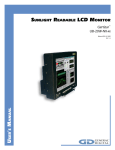
Download Lucas Industries EM-C061 User's Manual
Transcript
Lucas Control Systems Deeco Systems EM-C061 14" Flat Panel Display Embedded Computer Module USER MANUAL Manual P/N: 15062 Manual Revision: 1.0 Manual Revision Date: June 1997 How to contact Deeco Systems for sales or technical support: Lucas Control Systems, Deeco Systems 31047 Genstar Road Hayward, California USA 94544-7831 Phone: 1-800-376-1154 or 510-471-4700 FAX: 510-489-3500 General E-mail: [email protected] Internet: http://www.deeco.com Technical Support E-mail: [email protected] Technical Support BBS: 510-471-5402 Baud Rate: Data Bits: Parity: Stop Bits: Flow Control: Emulation: up to 14400 Baud 8 None 1 XON/OFF ANSI Europe Phone: 49-7024-9712-14 Europe FAX: 49-7024-9712-40 For Returns - Contact Deeco Systems’ customer service for a Return Authorization (RA) number prior to shipping product to the factory. Freight to the factory is prepaid by the customer. Freight return to the customer is paid by Deeco Systems. Ship product in its original packaging or equivalent to prevent transit damage. Copyright 1997, Lucas Automation and Control Engineering, Inc. (L.A.C.E., Inc.) All rights reserved. Deeco is a registered trademark of LACE, Inc. All other trademarks are the property of their respective owners. Information furnished by Deeco Systems is believed to be accurate and reliable. However, no responsibility is assumed by Deeco Systems for its use, nor for any infringements of patents or other rights of third parties which may result from its use. No license is granted by implication or otherwise under any patent rights of LACE, Inc. Printed in the USA. Warning!! Grounding circuit continuity is vital for safe operation of the machine. Never operate the machine with the grounding conductor disconnected. See installation instructions before connecting to the supply. The computer system contains voltages capable of producing a dangerous electrical shock. Only properly trained and authorized personnel should access the computer. CAUTION: DISCONNECT POWER BEFORE SERVICING. Table of Contents 1.0 OVERVIEW............................................................................................................................. 1 1.1 PRODUCT SUMMARY............................................................................................................ 1 1.2 INDUSTRIAL COMPUTERS ................................................................................................... 2 1.3 SINGLE BOARD COMPUTER ................................................................................................ 2 1.4 ORDERING INFORMATION.................................................................................................... 3 1.5 SPECIFICATIONS ................................................................................................................... 5 1.6 DISPLAY.................................................................................................................................. 6 2.0 INSTALLATION .................................................................................................................... 7 2.1 UNPACKING ........................................................................................................................... 7 2.2 MOUNTING............................................................................................................................. 8 2.3 APPLYING POWER................................................................................................................. 8 2.4 POWER REQUIREMENTS ....................................................................................................... 9 3.0 SINGLE BOARD COMPUTER OPERATION ................................................................... 11 4.0 TOUCH SYSTEM................................................................................................................. 13 5.0 INPUT/OUTPUT INTERFACE PORTS............................................................................... 15 5.1 SERIAL COMMUNICATIONS PORT..................................................................................... 15 5.2 PARALLEL COMMUNICATIONS PORT............................................................................... 15 5.2.1 Port Address Selection....................................................................................................... 15 5.2.2 Parallel Port Connector .................................................................................................... 16 5.3 KEYBOARD PORT................................................................................................................. 17 5.4 NETWORK COMMUNICATIONS PORT............................................................................... 17 5.4.1 10 BASE-T Connector ....................................................................................................... 18 5.4.2 10 BASE-2 Connector........................................................................................................ 18 6.0 DATA STORAGE .................................................................................................................. 19 6.1 HARD DRIVES: ...................................................................................................................... 19 6.2 SOLID STATE DISKS: ........................................................................................................... 19 6.3 FLOPPY DRIVES.................................................................................................................... 19 7.0 GENERAL MAINTENANCE................................................................................................ 21 7.1 EFFECTS OF CHEMICALS ON THE OPTIONAL SEALED BEZEL/FILTER....................... 21 8.0 TROUBLESHOOTING......................................................................................................... 23 8.1 POWER SUPPLY .................................................................................................................... 25 8.2 TOUCH INTERFACE.............................................................................................................. 26 8.2.1 Controller Board ........................................................................................................ ...... 26 8.3 DISPLAY................................................................................................................................. 27 i 8.4 SINGLE BOARD COMPUTER................................................................................................ 27 9.0 COMPONENT TEST PROCEDURE.................................................................................... 29 9.1 POWER SUPPLY..................................................................................................................... 29 10.0 COMPONENT INSTALLATION AND REMOVAL.......................................................... 33 10.1 TOUCH CONTROLLER BOARD .......................................................................................... 35 10.1.2 Installation ...................................................................................................................... 35 10.2 MEMORY REMOVAL AND INSTALLATION..................................................................... 35 10.2.1 SIMMs Removal............................................................................................................... 35 10.2.2 SIMMs Installation .......................................................................................................... 36 10.3 MICROPROCESSOR REMOVAL AND INSTALLATION.................................................... 37 APPENDIX A: MECHANICAL DRAWINGS ............................................................................ 39 A.1 EM-C061 COMPUTER FRONT VIEW................................................................................... 39 A.2 EM-C061 COMPUTER REAR VIEW ..................................................................................... 40 A.3 EM-C061 SIDE VIEW ............................................................................................................ 41 A.4 EM-C061 CABLING DIAGRAM ............................................................................................ 42 A.5 EM-C061 PANEL CUT-OUTS AND MOUNTING GUIDE .................................................... 43 APPENDIX B: PRODUCT NAMING CONVENTION .............................................................. 45 LIMITED WARRANTY.............................................................................................................. 47 INDEX .......................................................................................................................................... 49 ii EM-C061 Computer User Manual 1.0 Overview Lucas Control Systems, Deeco™ Systems offers a complete line of rugged computers, VGA monitors, and terminals. These products are available in sealed standalone enclosures, with panel mount brackets, and as embedded modules. All Deeco Systems products are available with touch systems for a complete user interface. Deeco Systems has manufactured quality flat panel display based products for harsh and industrial applications for more than a decade. The EM-C061 embedded computer module is an industrial Pentium®-based PC with a color TFT LCD 13.8" flat panel display. The computer can be 19″ rack-mounted or easily integrated into panel cut-outs or OEM equipment. The EM-C061 is available with a resistive touch screen system that functions as a touch mouse. 1.1 • PRODUCT SUMMARY 100, 133, 166 or 200 MHz Pentium processor. • Available with a high resolution resistive touch system. Touch mouse software lets your finger work like a mouse. Performs under the most extreme conditions and responds accurately -- even when the operator is wearing gloves. • Optional NEMA 4/12 (IP65) sealed bezel available. Optional panel mount frame simplifies NEMA 4/12 (IP65) seal to enclosure. • Color XGA AM TFT flat panel display • Optional rugged hard drive up to 3.26GB 3.5″ SCSI3 or 2.11GB Ultra SCSI, and 2.0 rugged 2.5″ PIO4 (EIDE) -- (SCSI drives require one PCI card slot). • Optional PC/104 Semiconductor Disk from 2 - 8MB. • Optional Ethernet - 10 BASE-T and 10 BASE-2. • Four full size ISA card slots or 2 PCI and 2 ISA card slots available (Note: One PCI slot is needed for SCSI controller if SCSI hard drive is installed.) 1 EM-C061 Computer User Manual 1.2 INDUSTRIAL COMPUTERS Deeco computers are designed for industrial conditions and exposure to harsh environments including extended high and low temperatures, high and low humidity, and severe shock and vibration. The optional sealed front bezel meets NEMA 4/12 (IP65) requirements. Deeco computers are available with Deeco’s Power Assist factory automation software, which speeds implementation of the EM-C061 in industrial control applications. Experienced Applications Engineers are available to help customers integrate computers into special situations. The EM-C061 is available with integrated 13.8" AM color TFT LCD with XGA resolution (1024 x 768) and up to 4K colors. The systems are available with resistive touch system and touch mouse software. These allow the operator to establish mouse control directly from the display by pointing and dragging a finger over the display. Modified mouse drivers are loaded in the hard disk at the factory. These enable the user’s finger to emulate a standard mouse. Available mouse drivers include MS-DOS/Windows™, Windows 95, Windows NT, and OS/2. 1.3 SINGLE BOARD COMPUTER The EM-C061 uses a Pentium-class 100% PC-AT compatible industrial single board computer (SBC). The SBC supports up to 64 MB of 72-pin SIMM DRAM, in increments of 4, 8, 16, 32 or 64 MB configurations. The SBC comes with an integrated peripheral controller for floppy disks, up to 4 EIDE hard disks, two external serial ports (one if the touch option is ordered), and a bi-directional parallel port. Also included is an on-board C&T 655xx 32-bit CRT/LCD controller. All DOS-based software, Windows 3.1, Windows 95, Windows NT, Novell NetWare, UNIX, and OS/2 are supported. Software can be ordered pre-installed. Power-up self-test diagnostics, a programmable watchdog timer, and Green PC energy management are standard features of the EM-C061. Detailed information and specifications for the Single Board Computer are in the separate SBC manual. 2 EM-C061 Computer User Manual 1.4 ORDERING INFORMATION Base System Configuration Select a Computer and Chip Set *a ❏ ❏ ❏ ❏ 123 120 121 122 Full Size ISA/PCI SBC, 100 MHz Pentium Full Size ISA/PCI SBC, 133 MHz Pentium Full Size ISA/PCI SBC, 166 MHz Pentium Full Size ISA/PCI SBC, 200 MHz Pentium Select Memory 72-Pin EDO SIMM ❏ ❏ ❏ ❏ 211 212 213 214 8MB SIMM 16MB SIMM 32MB SIMM 64MB SIMM Select a Display ❏ 3261 XGA (1024 x 768) up to 4K colors, 13.8", AM Color TFT LCD Upgrades and Options Select a Power Supply *b ❏ ❏ 703 704 +20-36 VDC 90-264 VAC, 47-63 Hz Select Input Device Option (select either or both) ❏ ❏ 416 412 14" Sealed Bezel, no touch 14" Sealed Bezel, resistive touch, controller Backplane Expansion Option *c ❏ ❏ 1403 1404 4 slot ISA full-size backplane 2 PCI and 2 ISA full-size backplane Mounting Option ❏ 1502 ❏ 1503 Open Frame, Rack Mount Open Frame, Panel Mount Hard Drives *d ❏ ❏ ❏ ❏ ❏ 518 520 521 522 523 1.3GB, rugged 2.5" PIO4 (EIDE) 2.11GB, 3.5" Ultra SCSI (Requires PCI card slot) 3.26GB, 3.5" SCSI3 (Requires PCI card slot) 2.0GB, 2.5" rugged PIO4 (EIDE) 340MB, rugged 2.5" PIO4 (EIDE) 3 EM-C061 Computer User Manual Floppy Drive ❏ 600 Mounted Floppy Drive (Rear Access) PC/104 Semiconductor Disks ❏ 1010 ❏ 1011 2MB on PC/104 Card 8MB on PC/104 Card Ethernet LAN Communications *e ❏ 904 10BASE-T (T-pair) / 10BASE-2 Software - Operating Systems ❏ ❏ ❏ ❏ 800 803 811 812 Microsoft Windows 3.1 DOS Microsoft Windows 95 Microsoft Windows NT for Workstations Software - Touch Drivers ❏ 816 DOS/Microsoft Windows 3.1 ❏ 817 Microsoft Windows NT Resistive Touch Mouse ❏ 818 OS/2 Resistive Touch Mouse ❏ 820 Microsoft Windows 95 Resistive Touch Mouse Software - Process Automation ❏ ❏ ❏ ❏ 807 808 814 819 Power Assist Developer Kit, DOS Power Assist Run Time Kit, DOS Power Assist for Windows-Developer Power Assist for Windows-Run Time Special Ordering Information *a Includes video graphics chipset for 14” high resolution display. *b If power supply not ordered user must provide +12VDC and +5VDC. *c Requires option 703 or 704 power supply. *d All disk drives are mounted to maximize shock and vibration requirements. SCSI hard disk drives require a PCI controller card, which means the 1404 backplane option is required. *e Use PC/104 if backplane option is not chosen. ISA or PCI card will be used if backplane option has been selected. 4 EM-C061 Computer User Manual 1.5 SPECIFICATIONS CPU Pentium processor up to 200 MHz L2 Cache 512K pipeline burst mode Displays 13.8" XGA (1024 x 768), AM Color TFT LCD Video Controller Chips and Technology 65XXX Memory Includes two to four 72-pin SIMM sockets supporting up to 128 MB DRAM Connectors Serial Parallel Network (optional) Keyboard Weight 26 lbs (11.82 kg) Dimensions (1502) Standard With Optional Front Panel 11.5" H x 14.4" W x 4.0" * D (292 mm x 366 mm x 102 mm) 12.3" H x 15.2" W x 4.0" * D (312 mm x 386 mm x 102 mm) *Add 2.2" to depth for optional backplane. Temperature Operating 0oC to +50oC Non-operating -25oC to +65oC Shock (MIL-STD-810D) 10G 50G 1.0G rms 3.0G rms (tested with 2.5" HD) Vibration (Broadband Spectrum 10-500 Hz per MIL-STD-810D) (tested with 2.5" HD) Humidity 5% to 95% RH, non-condensing Power Input +24 VDC or 100-240 VAC input or +5V, +12V MTBF (nominal) (@25oC) SBC/controller > 80,000 hours Display > 45,000 hours* *AMTFT display backlights are considered field replaceable items and are not included in MTBF figures. 5 EM-C061 Computer User Manual 1.6 DISPLAY The display is color active matrix LCD incorporating amorphous silicon TFT. Graphics and texts can be displayed on the 1024 x 768 color panel. The TFT panel used is a low-reflection and highercolor saturation type. AMTFT technology is rapidly changing. The EM-C061 uses the latest technology in flat panel displays. 6 EM-C061 Computer User Manual 2.0 INSTALLATION Read this section prior to installing the computer. Following these steps will ensure a successful installation of the computer system. 2.1 UNPACKING Components used in these systems are electrostatic sensitive. Observe proper electrostatic discharge (ESD) procedures when unpacking and handling the computer. The shipping configuration of the EM-C061 will vary according to the options ordered. The following configuration is only a general guideline: AC Power cord, +24VDC power cable, or pigtail for ±12 V, ±5V operation. Serial cable with 2 9-pin DSUB connectors. If touch option is ordered, only one serial connector (com1) is available for external use. Single Board Computer manual. Operating system software. A panel mounting gasket if the panel mount option is ordered. Touch Driver Diskette if touch option is ordered. The touch manual is on the diskette. SSD Documentation if the SSD option is ordered This User Manual. Remove the computer from the protective wrapping and inspect the unit for any obvious damage incurred during shipping. Contact the shipper if any damage is noted. 7 EM-C061 Computer User Manual 2.2 MOUNTING The EM-C061 is designed to be mounted in enclosures, rack-mounted, mounted in walls, and integrated in systems. Other arrangements can be used as long as these standard criteria are met: • When the unit is safely mounted the installation must be able to support at least five times the unit’s weight. The unit must be rigidly fastened so that when the touch screen is used the unit will not move or fall over. The weight of the unit is 26 lbs (11.82 kg). • The mounting surface should not be a hot wall. • The unit should be mounted for optimum visibility of the display. Typically, this is at or slightly above eye level. Avoid looking down on AM TFT displays from directly above, as the viewing angle is not as good as in other planes. • Use the optional bezels or other transparent window to protect the display from impact. Please refer to cut-out panel in Appendix A. 2.3 APPLYING POWER Prior to applying power to the computer system the user should connect all peripheral equipment including printers, Ethernet, external floppy drives, networks, etc. Refer to the section on I/O ports for location information on peripheral connections. Once all associated equipment has been properly connected, the user can make the power connection. Once power is applied, the computer will run a series of system self tests. Upon completion of these tests, the computer will open the operating system. 8 EM-C061 Computer User Manual 2.4 POWER REQUIREMENTS The following table specifies the electrical requirements and capabilities of the power supplies available for the computer system. Power Supply Option Voltage Current Frequency Watts Option 703 20-36 VDC 6.7 - 3.7 A DC 100 W Option 704 100-240 VAC 1.25 - 2.5 A 47-63 Hz 100 W Customer Supplied ±5, ±12V +5 8A DC 40 W -5 1A DC 5W +12 4A DC 48 W -12 1A DC 12 W Option 703 DC Supply: Connect 20-36 V input power to the pigtail as shown: 24 VDC Return Ground Option 704 AC Supply: Connect 100-240VAC input power to the pigtail as shown. Line Neutral Ground 9 EM-C061 Computer User Manual Customer Supplied ±5, ±12V: Connect ±5, ±12V and Ground to the pigtail as shown: +5V Ground Ground +12V -12V -5V 10 EM-C061 Computer User Manual 3.0 Single Board Computer Operation The separate Single Board Computer (SBC) user manual contains setup, operation, and maintenance documentation for the SBC. The SBC is factory configured by Deeco Systems, and modifications are usually unnecessary. 11 EM-C061 Computer User Manual 4.0 Touch System Refer to the manual on the Touch Driver Diskette for information on the optional touch system. Touch drivers are pre-installed at the factory and reside on the mass storage device. 13 EM-C061 Computer User Manual 5.0 Input/Output Interface Ports 5.1 SERIAL COMMUNICATIONS PORT The computer includes two serial ports, configured as COM1 and COM2. Refer to the SBC manual for configuration information. The EM-C061 includes a 12" cable with two 9-pin DSUB connectors, so customers can access the two serial ports. COM2 is disconnected from the DSUB connector on the cable and used by the touch screen when the optional touch screen is ordered. Both serial connectors are PC standard male 9-pin DSUB connectors with the standard PC pin out: Pin I/O Description 1 <I DCD 2 <I RX 3 >O TX 4 >O DTR 5 Gnd (Signal Ground) 6 <I DSR 7 >O RTS 8 <I CTS 9 <I RI 5.2 PARALLEL COMMUNICATIONS PORT The SBC provides a fully compatible IBM AT bi-directional printer port. 5.2.1 Port Address Selection By default, the printer port is configured as LPT1. Refer to the separate SBC User Manual for more information. 15 EM-C061 Computer User Manual 5.2.2 Parallel Port Connector The parallel port uses a 25-pin IDC style DSUB. The pin out for the connector is: Pin 1 2 3 4 5 6 7 8 9 10 11 12 13 Dir O I/O I/O I/O I/O I/O I/O I/O I/O I I I I Name/Description -SROBE PD0 PD1 PD2 PD3 PD4 PD5 PD6 PD7 -ACK BUSY PE SLCT Pin 14 16 16 17 18 19 20 21 22 23 24 25 16 Dir O I O O - Name/Description -AUTOFD -ERROR -INIT -SLCTIN GND GND GND GND GND GND GND GND EM-C061 Computer User Manual 5.3 KEYBOARD PORT The computer supports an AT style 101 Keyboard. Keyboard Connector (Rear View) 5.4 Pin 1 2 3 4 5 Signal KeyClk KeyData NC GND VCC 3 1 5 4 2 NETWORK COMMUNICATIONS PORT Ethernet is the most widely used of all LAN protocols. Typical characteristics of the Ethernet are: Bandwidth 10 MB/Sec Protocol CSMA/CD Frame Size 1514 bytes Max. Nodes 1024 Max. Network Span 2.8 Km There are 3 basic topologies. Characteristics of each are shown below: Media 10 BASE-T 10 BASE-2 Topology STAR (Twisted Pair) BUS (Multi-Point) Segment 100 Meters Cable Connection 24 AWG, 100 ohm, 8 pin, RJ45 185 Meters RG58, BNC ‘T’ 10 BASE-T is most popular because of its low cost and easy installation. Also, UTP’s star topology allows the rest of the network to function correctly even if a break occurs in a particular segment. Cable length is limited to 100 m for twisted pair wires. The EM-C061 can be ordered with 10 BASE-T and 10 BASE-2 connectors. Both connectors are available when the Ethernet option is ordered. 17 EM-C061 Computer User Manual 5.4.1 10 BASE-T Connector Ethernet Network Interface RJ45 Connector Pin-Out 1 2 3 4 5 6 7 Front View Pin 1 2 3 4 5 6 7 8 Signal TX+ TXRX+ NC NC RXNC NC 5.4.2 10 BASE-2 Connector The 10 BASE-2 connector is a BNC type COAX connector. 18 8 EM-C061 Computer User Manual 6.0 Data Storage 6.1 HARD DRIVES: Drive Type 1.3GB, rugged 2.5″ PIO4 (EIDE) 2.0GB, rugged 2.5″ PIO4 (EIDE) 2.11GB, 3.5″ Ultra SCSI (Requires PCI card slot) 3.26GB, 3.5″ SCSI3 (Requires PCI card slot) 340MB, rugged 2.5″ PIO4 (EIDE) The hard drive is preconfigured and preloaded with all software options at the factory. 6.2 SOLID STATE DISKS: Refer to the separate SSD documentation shipped with the 2 MB or 8 MB SSD options. 6.3 FLOPPY DRIVES Refer to the separate SBC manual for information on connecting a floppy disk drive. 19 EM-C061 Computer User Manual 7.0 General Maintenance The bezel and filter are made of a plastic polymer material, so strong solvents or acids should not be used for cleaning purposes. A soft, lint-free cloth, along with a non-abrasive, non-acidic cleaner can be used to clean the touch screen. Ammonia based cleaners are fine. 7.1 EFFECTS OF CHEMICALS ON THE OPTIONAL SEALED BEZEL/FILTER Chemical Resistance The active area of the touch screen is resistant to the following: Acetone Butyl Cellosolve Cyclohexanone Ethyl Acetate Hexane Isopropyl Alcohol MEK Methylene Chloride Toluene Xylene 40% NaOH Clorox Coffee Downy Fantastik Formula 409 Grape Juice Ketchup Lemon Juice Mineral Spirits Mr. Clean Mustard Spray'N'Wash Tea Tomato Juice Top Job Turpentine Vinegar Wisk 21 EM-C061 Computer User Manual 8.0 Troubleshooting Lucas Deeco maintains a repair facility at the factory and at various international locations. Call Technical Support and ask for a RA (return authorization) number before shipping computers needing repairs. Use the telephone number in the front of this manual. If the computer suddenly ceases to function, disconnect the power, and re-seat all the cables on their connectors. Be careful to re-connect all the cables correctly. Sometimes computer problems have simple, easy-to-correct causes. Before doing anything else, carefully check these solutions/tips. Power • Is your computer connected to a working wall outlet? • Is the power cord plugged firmly into the wall outlet and into the computer? • Is your computer turned on? Are the power lights illuminated? Cables • Are all cables connected properly and securely? Startup • Was the diskette drive empty when you started the computer? (If not, eject the diskette and try restarting your computer.) If all these have been checked and there is still a problem please see if the problem is listed below and then check the appropriate sub-system. Problem: System does not boot, or boots improperly. Sub-System to Check: • Fuse • Single Board Computer (Refer to the accompanying SBC manual) • BIOS system (Refer to the accompanying SBC manual) • Power Supply • Memory Systems 23 EM-C061 Computer User Manual Problem: Malfunctioning Display Sub-System to Check: • Display • Single Board Computer Motherboard (Refer to the accompanying SBC manual) • Power Supply Problem: Malfunctioning Memory Systems Sub-System to Check: • Single Board Computer Motherboard (Refer to the accompanying SBC manual) • BIOS System (Refer to the accompanying SBC manual) Problem: Mouse pointer unresponsive to touch Sub-System to Check: • Mouse Drivers • Touch controller Problem: Serial, Parallel, External Floppy Drive, Keyboard I/O Malfunction Sub-System to Check: • Single Board Computer (Refer to the accompanying SBC manual) • BIOS System (Refer to the accompanying SBC manual) • Cabling If after following the appropriate troubleshooting guidelines you cannot determine the nature of the problem, contact Deeco technical support. 24 EM-C061 Computer User Manual 8.1 POWER SUPPLY • Input Power: Check to see if the input power to the power supply meets the requirement in section 2.4 of this manual. Refer to section 9.1 for power supply test procedures. If the measured input power is not within the values shown, provide an alternative source of input power to the computer that satisfies the proper input power requirements. If the measured power falls within the values shown, proceed to the next troubleshooting guideline in section 9.1. • Output Power: Refer to section 9.1 for procedures for testing the power supply output. 25 EM-C061 Computer User Manual 8.2 TOUCH INTERFACE 3.3" (84 mm) 3.0" (76 mm) E271-2210 ELOGRAPHICS, INC. LED P4 - + 1.8" (46 mm) 2.1" (53 mm) Power 1x2 M RS-232 Serial 2x5 M P2 P3 5 L AccuTouch Y S 1x5 M X H H1 J0 •1 2 3 4 5 6 7 8 9 10 11 1 0.15" (4 mm) 0.156" (4 mm) 8.2.1 Controller Board • Input Power: Check to see if the input power to the controller board meets the specifications in the following table. Pin Power + Ground +5 VDC If the measured input power is incorrect, refer to section 9.1 to test for possible power supply malfunctions. If you are receiving correct power, move on to the next troubleshooting guideline. • Touch Frame Cables: Ensure that the 5-pin touch frame cable is properly seated at header P3. If the touch problem persists, move on to the next troubleshooting guideline. SBC Interface Cable: Ensure that the SBC Interface cable is properly seated at header J8 of the controller board. 26 EM-C061 Computer User Manual 8.3 DISPLAY Verify that the cable is properly connected to the SBC. Replace the cable as a part of test procedure. If display still does not work contact application engineering or otherwise return the unit to the factory. 8.4 SINGLE BOARD COMPUTER Input Power: Using the multi-meter, check to see if the input power to the SBC meets the voltage. Make sure that power pins are not shorted during the measurements. Refer to the SBC manual for power connector pinout. If the measured input power is incorrect, refer to section 9.1 to test for possible power supply malfunctions. If the motherboard is receiving correct power, move on to the next troubleshooting guideline. • SBC Mounting: Make sure that the solder side of the SBC is insulated from making contact with the case of the computer system. Any shorting of the SBC can cause system failure and damage to the SBC. • Strapping Fields (Jumper Settings): Refer to the accompanying SBC manual. • SIMMs: Check the SIMMs to verify that they are properly installed. Missing or incorrectly aligned SIMMs will prevent the SBC from operating. Refer to section 10.2 and the accompanying SBC manual for details on proper installation procedures. 27 EM-C061 Computer User Manual 9.0 Component Test Procedure 9.1 POWER SUPPLY This section details the procedures for testing the functionality of the power supply. Warning: • The power supply produces DC voltages that can cause a severe electric shock if handled improperly. Disconnect power before opening. Input Power: Plug the computer into the desired power source. The voltage should fall within this range at the power supply input connector. Option 703, @ connector J1 Pin 1 2 3 Power Ground - (Return) +20 to +36 VDC Pin 1 2 3 Power Ground Neutral 100-240 VAC at 47-63 Hz Option 704, @ connector J1 If the measured input voltage is not within the values shown, send the unit back to the factory for power supply replacement/repair. 29 EM-C061 Computer User Manual • Output Power: Using a multi-meter set for DC voltage, measure the potential between ground and the pins in the following table. The voltage should match the values shown when the supply is loaded. Pin 1 2 3 4 5 6 7 Supplies 703, 704 Function +5 VDC +5 VDC +5 VDC Ground Ground Ground Ground 30 Pin 8 9 10 11 12 13 14 Function +12 VDC +12 VDC NC -12 VDC KEY -5 VDC Isolated Return EM-C061 Computer User Manual If no output is measured, disconnect the power supply from source voltage and check the fuse on the power supply board. • Fuse: Remove the fuse from the power supply. Measure the resistance with an ohmmeter. If the fuse is open, replace the fuse on the power supply. Power Supply Order Number 703 704 Description +24 VDC 100W 100-240 VAC 100W Value of F1 A/250 VAC, Fast Blow 2A/250 VAC, Fast Blow Different suppliers may qualify as power supply vendors. Always match replacement fuses to original fuses. Warning: For protection against fire replace the fuse only with the same type and rating of fuse. Some power supplies have axial fuse holders. Place a screwdriver on the metal portion of the fuse, and gently lift the fuse from the socket. Some power supplies have fuse holders with round caps. These fuse holders are sealed with a silicon RTV type adhesive. Break the silicon seal. Use a flat bladed screwdriver to gently open the top of the fuse holder, then remove the fuse. Apply a suitable adhesive to the fuse holder cap upon re-assembly to preserve the computer’s shock and vibration specifications. Removing an Axial Power Supply Fuse With a Screwdriver (Photo used for illustrative purposes only. Models and configurations may vary.) 31 EM-C061 Computer User Manual 10.0 Component Installation and Removal Rear View 33 EM-C061 Computer User Manual Right Side View (Viewed from Front) Left Side View (Viewed from Front) 34 EM-C061 Computer User Manual 10.1 TOUCH CONTROLLER BOARD 10.1.1 Removal • Place the computer face-down on a flat surface. • Remove the 5-pin touch screen flex cable from P3 on the touch controller. • Remove the serial interface cable from the P2 header on the controller board. • Remove the 2-pin power cable. • Remove the 4 Phillips mounting screws holding the controller board to the side panel on the computer chassis. • Remove the touch controller from the computer system. 10.1.2 Installation To install the touch controller, simply reverse the order of the removal procedures specified in the previous sections. 10.2 MEMORY REMOVAL AND INSTALLATION Refer to the accompanying SBC User Manual for SIMM removal and installation. 10.2.1 SIMMs Removal • Place the computer face-down on a flat surface. • Gently press the retaining clips on each end of the SIMM socket outward until the SIMM comes loose form the retaining tabs. Gently pull the SIMM module out of the socket of the motherboard. 35 EM-C061 Computer User Manual 10.2.2 SIMMs Installation Figure A Figure B (Photo used for illustrative purposes only. Models and configurations may vary.) • Insert the SIMM at an angle as shown in Figure A. The SIMM will not physically fit in the socket unless pin 1 of the SIMM matches pin 1 of the socket. • Gently press the SIMM into the vertical position. The SIMM will snap easily into place if the connectors are at the correct depth in the socket. Refer to the SBC manual for memory configuration requirements. 36 EM-C061 Computer User Manual 10.3 MICROPROCESSOR REMOVAL AND INSTALLATION Chip Removal Tool Removing the microprocessor from the socket (Photo used for illustrative purposes only. Models and configurations may vary.) Refer to the accompanying SBC User Manual for microprocessor removal and installation guidelines. Make sure the jumper settings are matching the CPU speed! The heatsink is glued to certain microprocessors. Consult the factory for replacement microprocessors with similar heat sinks. Use a special IC replacement tool to remove the microprocessor from the socket When replacing the microprocessor, note the bevel on one corner of the IC. This designates pin 1. 37 EM-C061 Computer User Manual Appendix A: Mechanical Drawings A.1 EM-C061 COMPUTER FRONT VIEW 11.5" (292 mm) 14.4" (366 mm) Note: Dimensions shown without optional front panel. with front panel are 12.3" H x 15.2" W (312 mm x 386 mm) Drawing not to scale -- Dimensions are in inches (mm). 39 EM-C061 Computer User Manual A.2 EM-C061 COMPUTER REAR VIEW SBC in Standard Model Card Slots (2 PCI, SBC, 2 ISA slots or 4 ISA slots) with Backplane Option 14.4" (366 mm) 11.5" (292 mm) Power Supply Touch Controller Hard Drive / Floppy Drive Drawing not to scale -- Dimensions are in inches (mm). 40 EM-C061 Computer User Manual A.3 EM-C061 SIDE VIEW 2 PCI Slots SBC 2 ISA Slots 11.5" (292 mm) Power Supply Hard Drive Floppy Drive 4.0" (102 mm) without backplane 6.2" (157 mm) with backplane Drawing not to scale -- Dimensions are in inches (mm). 41 EM-C061 Computer User Manual A.4 EM-C061 CABLING DIAGRAM Touchscreen Display Touch Controller Floppy Disk Drive SBC FDD Option IDE HDD IDE HDD Option COM1 COM2 LPT1 KYBD SCSI HDD SCSI Controller SCSI HDD Option 42 EM-C061 Computer User Manual A.5 EM-C061 PANEL CUT-OUTS AND MOUNTING GUIDE 11.22" (284.99 mm) 1.39" (35.31 mm) 0.32" (8.13 mm) 5.29" (134.37 mm) 43 11.0" (279.40 mm) Suggested Panel Cutout for Mounting the EM-C061 Computer without the optional front panel 8.38" (H) x 11.22" (W) (212.85 mm x 284.99 mm) 8.38" (212.85 mm) 5.16" (131.06 mm) 0.09" (2.29 mm) EM-C061 Computer User Manual 14.50" (368.30 mm) 5.8" (147.32 mm) Suggested Panel Cutout for Mounting the EM-C061 Computer with the optional front panel 11.60" (H) x 14.50" (W) ( 294.64 mm x 368.30 mm) 5.8" (147.32 mm) Center Line 0.15" (3.81 mm) 2.5" (63.50 mm) 2.5" (63.50 mm) 7.25" (184.15 mm) 7.25" (184.15 mm) Center Line 44 11.60" (294.64 mm) 0.15" (3.81 mm) 0.11" (2.80 mm) EM-C061 Computer User Manual Appendix B: Product Naming Convention EM - C 0 6 1 Platform Type Processing Configuration ST Enclosed System EM Embedded Module Designator: 0 Computers Terminals Monitors 486 - Functional Type Display Size C T M 1 2 3 4 5 6 7 Computer, CPU-based Serial Terminal Monitor system 1 NA 8.4″″ 10.4″″ 11.3″″ 12.1″″ 13.8″″ 17.7″″ Case Style 0 1 2 3 4 5 6 No case Rack mount Medium Sealed Enclosure Swivel Housing Panel Mount Housing Large Sealed Enclosure Small Sealed Enclosure Examples ST-C461 EM-C031 Sealed Computer, Medium case, 10.4″ display, Pentium SBC Embedded computer, 10.4″ display, Pentium SBC *This refers to the type of CPU that the model was designed for but others CPUs may be substituted. 45 2 Pentium -* C9 Receiver Card Bus Card EM-C061 Computer User Manual Display Nomenclature 3fds Sequential number ID Size of display (same as specified in base unit ID #) 1 2 NA 8.4” 3 4 10.4” 11.3” Format 0 = VGA 1 = SVGA 2 = XGA 3 = SXGA 640.480 800.600 1024.768 1280.1024 Examples: 3261 = 14″ (13.8″) 1024.768 XGA display 3153 = 12″ (12.1″) 800.600 SVGA display 46 5 6 12.1” 13.8” 7 8 NA NA EM-C061 Computer User Manual Limited Warranty Lucas Control Systems warrants this product against defects in materials and workmanship for a period of one year (12 months) from the date of original shipment from the factory with the following exceptions: • Active Matrix LCD Display. The original equipment manufacturers warranty will apply. • Electroluminescent Display. The original equipment manufacturers warranty will apply. During this warranty period, Lucas Control Systems will, at no cost to the buyer, promptly repair or replace defective equipment returned to the factory or other authorized warranty repair center, transportation charges pre-paid by the buyer, and will return such equipment, transportation charges pre-paid. Lucas Control Systems’ sole obligation shall be at its option, to repair or replace any goods which have been determined to be defective by Lucas Control Systems. Equipment returned to the factory shall be accompanied by the following information: • Returned Material Authorization (RMA) number, obtained from Lucas Control Systems. • Reason for return, with a comprehensive description of the malfunction. • The name and telephone number of the person to contact in the event of questions or problems. • Shipping instructions. This warranty shall not apply to damage resulting from the improper handling, accident, negligence, loss or damage in transit, or abuse (such as applying the wrong voltage). This warranty shall be voided should the buyer attempt repairs or alterations without prior written permission from Lucas Control Systems. Lucas Control Systems makes no other warranty, either expressed or implied, and disclaims any warranty or merchantability or fitness for a particular purpose. Any action by Buyer for any alleged breach of this warranty shall be brought to the attention of Lucas Control Systems by the Buyer within the warranty period. Repairs and/or replacement under terms of this warranty shall not extend the warranty life of the original equipment supplied. 47 EM-C061 Computer User Manual LIMITATIONS OF LIABILITY THE BUYER AND LUCAS CONTROL SYSTEMS AGREE THAT THE SOLE AND EXCLUSIVE REMEDIES FOR BREACH OF ANY WARRANTY SHALL BE REPAIR OR REPLACEMENT OF DEFECTIVE PARTS ACCORDING TO THE TERMS DESCRIBED ABOVE. LUCAS CONTROL SYSTEMS SHALL NOT BE LIABLE FOR CONTINGENT OR CONSEQUENTIAL DAMAGES TO PERSONS OR PROPERTY, AND LUCAS CONTROL SYSTEMS’ SOLE LIABILITY IS AS SET FORTH ABOVE. THIS STATEMENT OF WARRANTY IS A COMPLETE AND EXCLUSIVE STATEMENT OF ALL WARRANTY AND LIABILITY REPRESENTATIONS OF LUCAS CONTROL SYSTEMS. IT MAY NOT BE VARIED, SUPPLEMENTED, QUALIFIED OR INTERPRETED BY ANY PRIOR DEALINGS BETWEEN THE PARTIES OR BY ANY USAGE OF THE TRADE OR UPON THE FACE OR REVERSE OF ANY FORM TO WHICH THIS IS ATTACHED OR PART OF, NOR MAY IT BE MODIFIED BY ANY AGENT, EMPLOYEE, OR REPRESENTATIVE OF LUCAS CONTROL SYSTEMS. 48 EM-C061 Computer User Manual Index 1 10 BASE-T Connector, 18 A Applying Power, 8 B BIOS, 23, 24 D Diagnostics, 2 DOS, 2 E Ethernet, 17 F Fuse, 31 G Green PC, 2 I Input Power, 25, 26, 27, 29 49 EM-C061 Computer User Manual L LAN, 17 LCD, 47 M Mounting, 8, 35 Mouse, 2, 17 N Novell, 2 O OS/2, 2 Output Power, 25, 30 P Parallel Port, 16 Power, 2 Power Requirements, 9 S SBC, 15 SIMM, 27, 35 Specifications, 5 T Touch, 26, 35 Troubleshooting, 23, 24, 25, 26, 27 U UNIX, 2 50 EM-C061 Computer User Manual W Windows, 2 51


