1
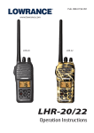
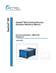
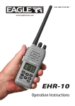
Pub. 988-0158-001
www.lowrance.com
LVR-850
DSC VHF Marine Radio
Installation and Operation
Instructions
Copyright © 2005 Lowrance Electronics, Inc.
All rights reserved.
Lowrance® is a registered trademark of Lowrance Electronics, Inc.
No part of this manual may be copied, reproduced, republished,
transmitted or distributed for any purpose, without prior written
consent of Lowrance. Any unauthorized commercial distribution
of this manual is strictly prohibited.
Lowrance Electronics may find it necessary to change or end our
policies, regulations, and special offers at any time. We reserve the
right to do so without notice. All features and specifications subject to
change without notice. All screens in this manual are simulated.
For free owner's manuals and the most current information on
this product, its operation and accessories,
visit our web site:
www.lowrance.com
Lowrance Electronics Inc.
12000 E. Skelly Dr.
Tulsa, OK USA 74128-2486
Printed in USA.
Table of Contents
Section 1: Installation .............................................................. 1
Introduction .................................................................................. 1
Powering Your Radio ................................................................ 1
Auxiliary Wires ......................................................................... 1
Bracket Installation .................................................................. 2
Antenna ......................................................................................... 3
How to Make a Distress Call........................................................ 4
Section 2: Basic Radio Operation .......................................... 5
Using the Keypad ......................................................................... 5
Power/Volume ........................................................................... 6
Squelch ...................................................................................... 6
H/L (High/Low) ......................................................................... 6
WX (Weather)............................................................................ 6
16/9 (Priority Channel) ............................................................. 6
SCN (Scan) ................................................................................ 6
MEM (Memory) ......................................................................... 7
CALL ......................................................................................... 7
DISTRESS................................................................................. 7
Arrow Keys ................................................................................ 7
PTT (Press to Talk) ................................................................... 7
DSC Calling vs. non-DSC Calling ................................................ 7
What is a DSC call? .................................................................. 7
How DSC works ........................................................................ 8
Simplex or Duplex..................................................................... 8
MMSI (Maritime Mobile Service Identity) .................................. 8
MMSI Setup .............................................................................. 9
Choosing a Channel .................................................................... 10
Making a Call.............................................................................. 10
Receiving a Call .......................................................................... 11
Section 3: Advanced Operation ............................................ 13
Calls ......................................................................................... 13
Transmission........................................................................... 13
AllShips Call........................................................................ 13
Directory Call ...................................................................... 14
Distress Call ........................................................................ 14
Last Call .............................................................................. 16
New Call .............................................................................. 16
Reception ................................................................................. 18
AllShips Call........................................................................ 18
Distress Call ........................................................................ 18
Geographic Call................................................................... 18
Individual Call .................................................................... 19
i
Channels.................................................................................. 19
Channel Bank ......................................................................... 19
Directory.................................................................................. 20
Storing/Editing MMSI Data ............................................... 20
DSC Monitor ........................................................................... 21
GPS Operation ........................................................................ 22
H/L ........................................................................................... 22
Memory Operation .................................................................. 22
Position Send/Request ............................................................ 23
Transmission ....................................................................... 23
Reception ............................................................................. 24
Priority Channel (16/9) ........................................................... 25
PTT (Push To Talk)................................................................. 25
Scan ......................................................................................... 25
Weather (Wx) .......................................................................... 27
Frequency Charts & Usage ................................................... 28
FCC Radio License and MMSI Number Information
In U.S. waters, vessels which are not required to carry radio equipment
are not required to have an FCC (Federal Communications Commission) ship station license for a VHF marine radio.
However, any vessel required to carry a marine radio on an international voyage, carrying a HF single side band radio telephone or marine
satellite terminal must have an FCC license.
License application forms for ship and land stations can be downloaded
free from the FCC web site at this address: www.fcc.gov/formpage.html.
You may also order copies of these forms by calling the FCC Forms Distribution Center at 1-800-418-3676.
At this time, the FCC does not require recreational boaters to have a
ship radio station call sign. The U.S. Coast Guard recommends using
the boat's registration number and state.
The BoatU.S. MMSI Program has been certified by both the Federal
Communications Commission (FCC) and the U.S. Coast Guard to assign MMSI numbers to vessels with DSC capable radios. To obtain and
register your free MMSI number, the Coast Guard recommends logging
onto http://www.boatus.com/mmsi/ and following the instructions.
ii
FCC Digital Device Compliance
This device complies with Part 15 of the U.S. Federal Communications Commission (FCC) Rules. Operation is subject to the following two conditions: (1) this device may not cause harmful interference, and (2) this device must accept any interference received, including interference that may cause undesired operation.
Changes or modifications not expressly approved by the manufacturer could void the user's authority to operate the equipment.
Note:
This equipment has been tested and found to comply with the
limits for a Class B digital device, pursuant to Part 15 of the
FCC Rules. These limits are designed to provide reasonable protection against harmful interference in a residential installation.
This equipment generates, uses and can radiate radio frequency
energy and, if not installed and used in accordance with the instructions, may cause harmful interference to radio communications. However, there is no guarantee that interference will not
occur in a particular installation. If this equipment does cause
harmful interference to radio or television reception, which can
be determined by turning the equipment off and on, the user is
encouraged to try to correct the interference by one or more of
the following measures:
•Reorient or relocate the receiving antenna.
•Increase the separation between the equipment and receiver.
•Connect the equipment into an outlet on a circuit different from
that to which the receiver is connected.
•Consult the factory customer service department for help.
iii
FCC Radio Frequency
Compliance Requirements and Warnings
When operating your marine radio transceiver, you should know that
the antenna radiates radio frequency (RF) energy. This radio was designed to meet the FCC’s rules and regulations for the maximum permissible exposure to radio frequency energy. This design was tested
and found to be compliant with the strict requirements established by
the FCC.
DO NOT operate the radio without a proper antenna attached, because
this may damage the radio and may also cause you to exceed FCC RF
exposure limits. Antenna types suited for this radio are described in the
installation section.
DO NOT transmit for more than 50% of the total radio use time.
Transmitting more than 50% of the time can cause FCC RF exposure
compliance requirements to be exceeded. The radio is transmitting
when the “TX indicator” is displayed on the screen. You can cause the
radio to transmit by pressing the "PTT" (Push To Talk) switch.
IMPORTANT: The antenna(s) used for this transmitter must be installed to provide a separation distance of at least 91 cm (37 inches)
from all persons (including passengers). The antenna(s) must not exceed an antenna gain of 3 decibels (dB) and must not be co-located or
operating in conjunction with any other antenna or transmitter.
iv
Section 1: Installation
Introduction
Thank you for purchasing the Lowrance LVR 850 DSC VHF Radio. We
know you’re anxious to try it out, but first, let us explain how this
manual can help you get the most out of your new radio.
We have designed this book so you don’t have to read the whole thing
from front to back to find the information you want. At the start of each
segment, we’ll tell you what content is coming up next. If it’s a concept
you're already familiar with, we’ll show you where to find the next important topic.
We lead off the manual with proper Distress Call procedures on page 4.
We put it at the front of the book to make it easy to find in case of an
emergency.
The first section covers LVR-850 installation and specifications.
The second section, Basic Radio Operation, goes over some basic functions of the radio and includes instructions on how to set up your MMSI
(Maritime Mobile Service Identity) number. You can't make a call
without it! To jump to MMSI setup, flip to page 8. To acquire a
free MMSI number, see the web address on the bottom of page
ii.
The third section, Advanced Radio Operation, offers more detailed information about the radio's features. The section will touch on all aspects of the radio's functionality, providing clear and complete explanations via a convenient alphabetical layout.
Let’s get started!
Powering Your Radio
(Power Supply cable – red and black wires)
The unit works from a 12-volt electrical system. You may attach the
radio to a 12-volt battery or to an auxiliary power panel.
If possible, keep the power cable away from other boat wiring, especially
the engine's wires. This will provide the best isolation from electrical
noise. The power cable has two wires, red and black. Red is the positive
lead, black is negative or ground. Make sure to attach the in-line fuse
holder to the red lead as close to the power source as possible.
Auxiliary Wires
The white and black auxiliary wires on the back of the unit connect
your radio to an external speaker. Connect the white (+) wire to the
speaker's positive lead, and connect the black (–) wire to the speaker's
negative lead.
1
The remaining auxiliary wires are used for DSC (Digital Selective
Calling) service, where the radio can exchange latitude and longitude
position information with a GPS (Global Positioning System) receiver
in NMEA 0183 format.
Receive +
To GPS unit
NMEA Transmit + (Orange)
Ground – (Yellow)
Shield – (Ground)
To Radio
Wiring to transmit NMEA information
to a GPS receiver.
NMEA Receive + (Brown)
Transmit +
To GPS unit
Ground – (Red)
Shield (Ground)
To Radio
Wiring to receive NMEA position information
from a GPS receiver.
Caution
All of the auxiliary wires have bare ends for easier installation.
The bare ends on any unused wires could cause an electrical
short if left exposed. To prevent this, you should cover the individual wire ends – either by capping them with wire nuts or
wrapping them with electrical tape.
Bracket Installation
Mount the unit in any convenient location, provided there is clearance
behind the unit when it's tilted for the best viewing angle. You should
also make sure there is enough room behind the unit to attach the
power, antenna and auxiliary cables. Pick a location far enough from
any compass to avoid compass deviation caused by the speaker magnet.
The radio must be installed at least three feet from the antenna. Make
sure there is space nearby to hang the mic clip.
Holes in the gimbal bracket's base allow wood screw or through-bolt
mounting. You may need to place a piece of plywood on the back side of
thin fiberglass panels to reinforce the panel and secure the mounting
hardware. We suggest that you use stainless steel screws for installation.
2
Screw
mounting
hole
Front
Install the gimbal bracket, which looks similar to the one pictured
here. Place the bracket so the arms slope toward the radio's front.
Once a location is determined, use the bracket as a template and mark
the mounting holes. Screw the bracket to the mounting surface. Be sure
to leave enough slack in the cables to allow tilting the unit.
Attach the unit to the gimbal bracket using the supplied gimbal knobs
and washers. Attach the cables and the unit is ready to use.
Antenna
A good antenna installation will optimize the performance of your marine radio. There is no height requirement for antenna installation, but
the higher it is mounted, the better the reception. That's because marine VHF radio signals travel only on a "line of sight" basis. An ideal
installation will give the antenna a clear view of the horizon in all directions.
The antenna may be mounted on a gunwale, rail or on flat surfaces like
a deck, roof or bulkhead. In the case of some sailboats and powerboats,
it may be attached to a mast or mast-like structure.
When installing your VHF marine antenna, be sure to keep it at least
three feet away from any other antenna or metal object. The antenna
also must be installed three feet away from the radio, and at least three
feet from any passengers or crew. Refer to the antenna manufacturer's
instructions for further installation information. You must also make
3
sure your antenna and its installation complies with all local and federal regulations. Never operate your radio unless it is connected to the
antenna.
The antenna must not exceed an antenna gain of 3 decibels (dB). The
antenna cable requires a PL259 connector, and the cable connects at
the back of the radio. For installations less than 25 feet, use RG58 coaxial cable. For installations greater than 25 feet, use RG-8/U coaxial
cable.
WARNINGS:
Using an antenna with gain greater then 3 dB can damage the radio and exceed the safe exposure limits for radio frequency (RF) energy.
Also, the energy from any VHF radio antenna can be
harmful, even one properly rated at 3 dB of gain! Do not
come in contact with the antenna while a transmission is
being sent. Be sure the antenna is installed where it is
separated from people by at least 3 feet of space.
How to Make a Distress Call
Speak slowly, clearly and calmly.
1. Select VHF Channel 16.
2. Press microphone button: "MAYDAY — MAYDAY— MAYDAY."
3. "THIS IS [your ship ID]."
4. "MAYDAY [your ship name]."
5. Tell where you are — what navigational aids or landmarks are near.
6. State the nature of your distress.
7. Give number of persons aboard and condition of any injured.
8. Estimate present seaworthiness of your ship.
9. Briefly describe your ship — meters, type, color, hull.
10. "I WILL BE LISTENING ON CHANNEL 16."
11. End message by saying "THIS IS [ship name/call sign] OVER."
12. Release the PTT key and listen. Someone should answer. If not, repeat call, beginning at Item 3 above.
WARNING
The following types of communication are prohibited by
the FCC: false distress calls; calls to any boat — excluding emergencies and radio tests; calls to or from a vessel
on land and obscene or profane language. Using obscene
or profane language could result in a fine of up to
$10,000.
4
Section 2: Basic Radio Operation
This section addresses the radio’s basic operations, which includes
MMSI (Maritime Mobile Service Identity) number setup. If you already
have your MMSI number programmed into the radio and have a strong
understanding of the radio's basic functions, move on to Section 3:
Advanced Radio Operation.
The Lowrance LVR-850 VHF
Marine Radio.
We're going to kick off the operation section with a brief description of
the radio's basic functions. That will be followed by some important information on Digital Selective Calling and basic instructions on how to
make and receive calls.
Using the Keypad
The keypad has eight keys: H/L (Hi/Lo), WX (Weather), 16/9 (Priority
Channels), SCN (Scan), MEM (Memory), CALL (Call) and ↑ ↓, the up-anddown arrow keys. When you press any of the keys a tone will sound. If
you push a key and a 3-beep tone sounds, there is an error or the function is not supported by the radio. You’ll notice several functions require you to hold down a key for a few seconds. In those cases, a single
beep sounds, then, after a few moments, a second beep will be heard to
let you know you have successfully changed the mode.
5
Power/Volume
The volume knob at the top right of the radio’s face is used to power up
the LVR 850. Turn the knob clockwise to turn on the radio. The unit
will start on Ch. 2, then switch to Ch. 16, its default priority channel.
Squelch
Squelch, the bottom knob on the radio’s face, helps the unit screen out
radio traffic resulting from signals that are too weak to transmit anything but noise. To adjust the squelch, turn it to the left until noise can
be heard. Turn it back to the right until the noise is eliminated.
DSC
Monitor
Memory Annunciator
Arrow
Keys
Channel
ID
Annunciator
USA
Channel
Bank
Character
field position
H/L (High/Low)
The H/L key gives you control over the radio's wattage. The high-end is
25 Watts. The low-end is 1 Watt. If the LO ANNUNCIATOR is off, the radio
will transmit at 25 Watts.
WX (Weather)
Dark clouds on the horizon? Press the WX key to enter the WX (WEATHER)
MODE and get the latest weather information. Use the ↑ ↓ keys to change
the WX channel.
16/9 (Priority Channel)
The 16/9 key is used to switch between priority channels. It also allows
you to exit various operation modes, ignore incoming calls and cancel
outgoing calls.
NOTE
Ch. 16 and Ch. 9 may only be used to make initial contact with a
vessel and nothing more. When there is an emergency, all Distress
calls will be broadcast on Ch. 16.
SCN (Scan)
The SCN (scan) key allows you to monitor numerous channels at the
same time. Scanning options include: PRIORITY SCAN, MEMORY SCAN AND
ALLSCAN.
6
MEM (Memory)
The MEM key may be used to initiate a Memory Scan and gives you the
option of adding or deleting channels from the radio's scan list memory.
CALL
By pressing the CALL key you can make a new call, return the last incoming call, place a call to all ships or to one of up to 10 stored MMSI
numbers from a saved directory.
DISTRESS
By lifting up the red cover and holding down the DISTRESS button for
three seconds, you will send a distress call to the Coast Guard and any
other ship within range of you.
Arrow Keys
Use the ↑ ↓ keys to scroll through the channels and various menu options.
PTT (Press to Talk)
The PTT key is the talk button on the microphone. Press and hold it
down to talk when making or receiving a call.
DSC Calling vs. non-DSC Calling
The LVR-850 supports two types of calls, Digital Selective Calls (DSC)
and non-Digital Selective Calls. A non-DSC call is the traditional
method where an individual hails another vessel on Ch. 16, then asks
the other party to switch to a working channel set aside for the desired
communication type. Once they have left Ch. 16 and the selected
working channel is clear, the individual hails the vessel again to initiate communication.
What is a DSC call?
A relatively new technology, digital selective calling (DSC) gives you
the capability to dial another boat directly via the vessel's MMSI (Maritime Mobile Service Identity) number, which functions much like a
phone number. Digital Selective Calling simplifies the calling process,
because you don't have to hail the vessel on Ch. 16 nor do you have to
verbally direct them to the working channel you want them to switch to
for communication. When their DSC radio receives your call, it automatically will switch to the channel you selected for communication.
The primary reason DSC was created was to enhance boater safety. It
does this in several ways. When working in tandem with a GPS unit, it
helps the Coast Guard respond more quickly to a Distress Call, since
the location of the vessel in distress will be automatically transmitted
when the signal is sent out. It will automatically repeat a distress signal every four minutes. That would come in handy if, as in the case of a
7
fire, you could not man the radio and fight the fire at the same time.
DSC calling also helps cut back the transmission traffic on Ch. 16, the
emergency priority channel.
How DSC works
A digital selective call uses a digital signal to transmit a pack of information that can include, the caller’s MMSI number, the MMSI of the
ship or ships being called, call priority and a frequency or mode request. Location and time of location may be entered manually or if an
active GPS unit is attached, transmitted automatically. DSC calls allow
you to contact a specific ship, a group of ships, a specific group of DSC
receivers, ships in a particular geographic area or all ships within
range of you. A DSC call may even be patched into a regular phone line
through a commercial coastal station. One of the key elements of a DSC
call is the ability to place an individual call directly to another vessel.
Simplex or Duplex
References to simplex and duplex channels are scattered throughout
this manual. Simplex channels transmit and receive messages on the
same frequency. Like a CB radio, only one message can be transmitted
at a time. A duplex channel transmits and receives messages on different frequencies. Like a telephone, it gives users the capability to
transmit and receive messages at the same time. You must choose a
simplex channel when making a DSC call!
MMSI (Maritime Mobile Service Identity)
Your Maritime Mobile Service Identity number (MMSI) is like a home
phone number. Other DSC (Digital Selective Calling) radios must enter
your number before they can contact you. But first, you must program
your number into your radio. If your MMSI number is not set up, the ID
ANNUNCIATOR will blink on the display.
CAUTION
You only have one chance to program your MMSI into your radio. Study this section carefully to ensure the MMSI is entered
correctly.
8
The figure above illustrates the MMSI number entry of 992344513.
If a valid MMSI is already stored in the radio's memory, you will not be
able to enter a MMSI number. If a 9-digit MMSI number has not been
programmed into the radio, you will not be able to make or receive DSC
calls. To enter your assigned MMSI number, follow the steps listed in
the MMSI Setup below.
Warning
Again, there is only one chance to do this procedure correctly, so go over this section carefully.
MMSI Setup
1. Hold down the CALL key for 5 seconds. The ID ANNUNCIATOR will blink
and a large "0" will be displayed alongside a small “16.” The big number
“0” is the MMSI digit you are entering and the small digit “16” is the
first MMSI character field position. For example, a small digit "2" represents the 2nd number from the left in your assigned MMSI. If the
number was "4" it would mean the big digit you were entering was the
4th number from the left and so on.
This example gives us a closer look at a number sequence from a MMSI
entry. The big numbers are the MMSI digits. The small numbers in the
lower right hand corner represent the digits' character field position.
The big digit 4 is the sixth number from left in the MMSI. The big digit
5 is seventh from left and the big digit 1 is eighth from left.
9
NOTE
You need only to modify the big (MMSI) digits. The small digits
(character field position of the MMSI digit) will be generated automatically.
2. Use the ↑ ↓ keys to enter the first digit of your MMSI number, then
press the MEM key to advance to the second digit. The small digit now
displays the 2nd character position with a big-digit "0" and small-digit
"2”. Press the ↑ ↓ keys to set the second MMSI digit and touch the MEM
key to store. Repeat the operation until all 9 digits have been entered.
After inputting your MMSI, press the MEM key to double-check each
digit.
NOTE
If there is an error in the entry procedure, press the 16/9 key to exit.
You can also turn off the radio to ensure the MMSI won't be stored.
After you are satisfied with the MMSI number you have entered, hold
down the CALL key for 5 seconds to store the number. The ID ANNUCIATOR
will stop blinking and the radio reverts to the main screen. Now you are
ready to make a DSC call.
Choosing a Channel
Before making a call to another vessel, check the VHF chart in the back
of this manual. You'll have to choose a simplex communication channel
authorized for the type of communication you desire.
Making a Call
The LVR-850 supports five DSC call types: ALLSHIPS CALL, DIRECTORY CALL,
LAST CALL, NEW CALL and DISTRESS CALL. The example below details a NEW
CALL. For information on the other call types, see page 13.
To place a DSC call
New Call
1. Select a simplex channel and press the CALL key once. LAST blinks.
2. Use the ↑ ↓ keys to select NEW CALL.
3. Press the CALL key again. You can now enter the MMSI data of the
vessel you want to contact.
4. Use the ↑ ↓ keys to enter the MMSI numbers, pressing MEM after
each digit. After completing MMSI entry, press the MEM key to verify
each number of the MMSI.
5. Press the CALL key and the radio will transmit the request. If there
is no ACK after 4 seconds, the radio transmits the call again. The radio
will stay in standby mode until an ACK is received, indicated by the
flashing ID Annunciator. If an ACK is not received, you can press the
10
call key again and the call is placed again. You can exit the call function at any time by pressing the 16/9 key twice.
CAUTION
Before transmitting, monitor the selected simplex channel to make sure
it is clear. This is a FCC requirement.
NEW and ID will blink
MMSI Digit
Digit number
Ch. 8 is
simplex
working
channel
For more in depth information on placing calls see page 13.
To place a non-DSC call:
When making a non-DSC call, you'll have to switch to a communication
channel after making initial contact, so be sure to select a channel
authorized for the type of communication you desire.
1. Select an appropriate communication channel.
2. Tune your radio to Ch. 16 or Ch. 9. Speak slowly and clearly, stating
the name of the vessel you are trying to contact followed by "this is
(your ship name and call sign)."
3. When the other vessel responds, say "go to (the desired channel number) over."
4. Switch to the other working channel. After you are sure it is clear,
call out to the other vessel, stating the vessel's name, followed by "this
is (your ship name and call sign)."
Receiving a Call
Reception of an individual call automatically establishes communication on the working channel requested by the caller. Your radio transmits an ACK (Acknowledgement) message back to the calling radio. If
11
the calling vessel’s MMSI matches a number stored in your directory,
the number's directory location is shown. If no match is made, the ID
ANNUNCIATOR blinks. If you want to respond to the calling vessel, just
press the PTT button on the microphone. Press the 16/9 key to ignore
the call. See page 18 to get more detailed information on call reception.
12
Section 3: Advanced Operation
This section will give a more detailed explanation of what your radio
can do. We'll start off with a breakdown of the types of DSC calls the
LVR-850 can transmit and receive. That will be followed by a brief description of how to place a non-DSC call. If you are comfortable with
your knowledge regarding transmission and reception of calls, skip
ahead to page 20 to see how to set up a MMSI Directory. On page 27,
there is information on the radio's weather function.
Calls
Transmission
The five DSC calling modes are:
1. AllShips Call: places a call to any ship in range of you.
2. Directory Call: dials number from MMSI directory.
3. Distress Call: executes an emergency call to Coast Guard and other
ships in range of you.
3. Last Call: dials last incoming call.
4. New Call: places call to caller not in the MMSI directory.
Press CALL then use the ↑ ↓ keys to scroll through the four choices
(DISTRESS CALL is a separate function, so it is not included in the calls
menu). The LAST CALL option always appears first.
Four call
sources
to use
AllShips Call
This feature gives you the option of placing a call to all ships within
range of you.
NOTE
This radio does not handle AllShips urgency or safety DSC calls.
AllShips
calls use
Ch. 6
1. Press the CALL key.
2. Use the ↑ ↓ keys to select ALLSHIP.
3. Press the CALL key to transmit.
13
Directory Call
See page 20 to learn how to setup a MMSI directory. To call a number
from your directory:
1. Use the ↑ ↓ keys to select a simplex-working channel.
2. Press the CALL key.
3.Use the ↑ ↓ keys to select the call type — DIR, LAST, NEW or ALLSHIPS. Select DIR, then press CALL.
4. Use the ↑ ↓ keys to choose a MMSI location number (1-10). The default number is the MMSI of the last used call.
5. Press the CALL key to transmit. The called radio will acknowledge
and a communication link will be established. Just press PTT to talk.
In the following example, Ch. 8 was used to call a MMSI stored in directory No. 3.
Choose
directory
mode
Waiting
for ACK
ACK blinks
until PTT is
pressed
When the ACK ANNUNCIATOR turns on, the calling channel has been tuned
in and a communication link established. Press PTT to talk.
Distress Call
In an emergency situation, lift the red cover on the front panel to make
a Distress call to the Coast Guard. Press and hold the DISTRESS key for
14
three seconds. The radio switches to Ch. 16 and a three-second on
screen timer begins to count down in the bottom right corner of the
screen. When it reaches zero, the call is sent out. To stop the call, let go
of the DISTRESS key. No message will be sent unless the timer counts
down to zero. Press the 16/9 key to cancel.
NOTE
If an inadvertent Distress call is sent out, make sure you're on Ch.
16 and quickly transmit a message to all vessels, canceling the Distress call.
3-second
timer
If the DISTRESS key is held down until the timer expires, the radio will
switch to Ch. 70 and a distress call will be sent out. The DSC Distress
message is transmitted at 25 watts.
The Distress message contains your MMSI, your position and the UTC
time acquired from your GPS, if you're using a GPS unit. The DISTRESS
ANNUNCIATOR is displayed during the transmission.
Distress
Message
being sent
Timer
expired
A loud 2-tone alarm sounds. This alarm cannot be stopped unless the
mode is canceled. Pressing the 16/9 or PTT key cancels the DISTRESS
WAITING MODE. If the mode is not canceled, the radio transmits the Distress message again every 4 minutes. A DISTRESS WAIT message will be
displayed on the screen.
NOTE
The Coast Guard is the only agency allowed to acknowledge a Distress call. An individual vessel's DSC radio will not automatically
respond with an acknowledgement.
15
When an ACK is received, the distress mode is automatically canceled and communication will be on Ch. 16.
Last Call
You can send a last call by following this sequence:
1. Use the ↑ ↓ keys to select a simplex-working channel. The radio will
default to Ch. 16 if a duplex channel is selected. (If you press the call
key during WX CHANNEL MODE, the last used channel is displayed.)
2. Press the CALL key.
3. LAST blinks.
Last
Call
Last caller
is No.4 in
Directory
4. Press the CALL key to transmit.
If there is no last call information stored, an error beep sounds. If the
last call is a MMSI number stored in your directory, the number's directory location will be displayed below the ID ANNUNCIATOR. After the
radio you're calling acknowledges the call, communication will be established as soon as you press the PTT button.
New Call
This procedure allows you to place an individual call.
1. Press the CALL key once. LAST blinks.
2. Use the ↑ ↓ keys to select NEW CALL.
3. Press the CALL key again. You can now enter the MMSI number.
NOTE:
New call MMSI numbers are not stored. They are for temporary
use. You must enter them into your directory to have the numbers
stored permanently.
16
NEW and ID Annunciators will blink
Channel
Character field
position
Ch. 8 is
simplex
working
channel
4. Use the ↑ ↓ keys to set proper MMSI data for the digit shown. After
correct verification of the first digit of the MMSI number, touch the
MEM key to advance. The small digit now displays the 2nd character
position with a "0" as the big digit and "2" as the small digit. Set the
second MMSI digit using ↑ ↓ keys and touch the MEM key to store. Repeat the operation until all 9 digits have been entered. Double-check
your MMSI entry, toggling through each individual digit by pressing
the MEM key. There is no backup or edit mode, so if you make a mistake
entering the number, you'll have to start over. Press the 16/9 key to exit
or just turn off the radio. After you are satisfied with the new MMSI
number, press the call key.
5. Press the CALL key and the radio will transmit the request. If there
is no acknowledgement (ACK) after 4 seconds, the radio transmits the
call again. The radio will stay in standby mode, indicated by the flashing ID Annunciator, until an ACK is received. If an ACK is not received,
you can press the call key again and the call is placed again. You can
exit the call function at any time by pressing the 16/9 key twice.
To place a non-DSC call:
When making a non-DSC call, you'll have to switch to a communication
channel after making initial contact, so be sure to select a channel
authorized for the type of communication you desire.
17
1. Select an appropriate communication channel.
2. Tune your radio to Ch. 16 or Ch. 9. Speak slowly and clearly, stating
the name of the vessel you are trying to contact followed by "this is
(your ship name and call sign)."
3. When the other vessel responds, say "go to (the desired channel number) over."
4. Switch to the other working channel. After you are sure it is clear,
call out to the other vessel, stating the vessel's name, followed by "this
is (your ship name and call sign)."
Reception
AllShips Call
When receiving any type of an ALLSHIP'S CALL, a ring tone sounds and the
calling radio's requested working channel is selected for communication. There is no ACK required from your radio. If you want to contact
the calling vessel, just press the PTT button.
Receiving an
Receiving
an
AllShips call
AllShips call
Distress Call
The reception of a DISTRESS CALL automatically sets the receiving radio's
channel to Ch. 16. Press the 16/9 key to turn off the distress alarm.
Distress
Calls switch
to Ch. 16
NOTE
The LVR-850 does not respond to two types of DSC Distress calls:
1. Distress relay from an intermediary vessel.
2. Distress relay acknowledgment (ACK) from a coastal station.
Geographic Call
The LVR-850 is able to receive geographic calls. When it does, a ring
tone sounds and the calling radio's requested working channel is chosen
for communication. There is no ACK required from your radio. If the
calling vessel's MMSI matches a number stored in the directory, the
directory location will be displayed in the lower right hand corner of the
screen. If you want to respond to the vessel, press the PTT button.
18
Receiving
Geographic
Call
Individual Call
Reception of an individual DSC call sets up communication on the
working channel requested by the caller. Your radio automatically
transmits an ACK (Acknowledgement) message back to the calling radio. If the caller's MMSI matches an entry in your directory, its location
will be displayed. If no match is made, the ID ANNUNCIATOR blinks. Press
16/9 to ignore the call. To respond to the vessel, press the PTT button.
Caller's
working
channel
ID
Match
Blinks if no
ID is found
in directory
Caller's
working
channel
Channels
To tune into one of the 84 channels on the LVR-850 radio, use the ↑ ↓
keys to scroll through the channels. Refer to the enclosed channel chart
in the back of this book for proper usage and understanding. In the US
and Canada, WX (Weather) channels are available. WX channels are not
available for international use.
An A ANNUNCIATOR will be displayed when an alternate channel is used.
That is telling you the radio is tuned to a simplex channel and normal
ship-to-ship communication is appropriate. If the A ANNUNCIATOR is off,
the radio is operating in duplex mode.
Channel Bank
The Channel Bank has three settings, one each for US, Canada and
International use. Press and hold the H/L and WX keys at the same time
to switch channel banks. The annunciator will display USA, INT or CAN
based on your selection. Refer to the channel chart appendix for proper
usage.
19
Directory
The Directory is an organized list of (up to 10) MMSI numbers stored
on the DSC calling directory.
Storing/Editing MMSI Data
To store a new MMSI in an unused location, follow these steps:
1. Press the CALL key to display LAST. Use the ↑ ↓ keys to select DIR.
The DIR ANNUNCIATOR blinks.
2. Press the CALL key. The ID ANNUNCIATOR starts to blink ON/OFF, indicating the directory EDIT MODE is activated.
DIR and ID
blink to
show Edit
mode
No. 3
is full
No. 4 is empty
and usable
3. Use the ↑ ↓ keys to select an unused location. If the number location
is full, FL is displayed. If the location is available, CL appears on the
screen.
4. Select the CL location and press the MEM key to advance to the MMSI
input screen.
5. Press the ↑ ↓ keys to enter the MMSI digits. After entering the first
MMSI digit, press the MEM key to enter the second number. The big
digit, again starts at "0" and the small digit now displays “2” The small
number will increase each time you add a MMSI digit. Use the ↑ ↓ keys
to set the second MMSI digit and touch the MEM key to store. Repeat
the operation until all 9 digits have been entered and verified. After
entering the MMSI, review each digit by pressing the MEM key. If there
is a mistake, press the 16/9 key to exit or just turn off the radio. The
MMSI will not be stored. After you are satisfied with your MMSI entry,
hold down the CALL key for 5 seconds to store the number.
6. Press the 16/9 key to revert to the main screen.
20
The example shows the MMSI Data 987776510 being entered.
To change or edit MMSI data, select a FL location and press the MEM
key to change the data. After inputting the 9-digit MMSI, hold down
the CALL key for 5 seconds to store the new MMSI.
DSC Monitor
To be sure the DSC Monitor mode is on, hold down the CALL key for 5
seconds to toggle the DSC Monitor mode off and on. It must be on for
your radio to receive a DSC call. The DSC MON ANNUNCIATOR will be displayed onscreen, if Ch. 70 is being accessed. Since there is no independent Ch. 70 receiver, the radio normally monitors Ch. 70 and checks
other channels on a regular basis to detect a squelch break. This
method ensures the radio will acquire the most DSC calls possible.
21
DSC Monitor must be
on for radio to receive
calls
NOTE
DSC calls will NOT be received when the radio is receiving or
sending out a transmission. During scanning, Ch. 70 is monitored
on an allocated time-slot basis and DSC calls will be received.
GPS Operation
Your radio is NMEA 0183 compatible, which means it can work with a
GPS unit. To be certain your location is autom+atically transmitted
during a distress call, make sure your GPS unit is on and operational at
all times. The GPS data is sent through Ch. 70 to the coast guard and is
the primary starting point of any search and rescue mission. If THE GPS
ANNUNCIATOR is blinking, the GPS data is not valid.
GPS
Annunciator
H/L
The H/L key gives you control over the radio's wattage. The high-end is
25 Watts. The low-end is 1 Watt. If the LO ANNUNCIATOR is off, the radio
will transmit at 25 Watts. Some channels do not accept transmissions
or are restricted to a 1-Watt level. If you come across one of those channels and you try to switch to 25W, you will hear a 3-tone error beep,
meaning you either can not transmit on that channel or it only accepts
transmissions at the 1W (Lo) level.
Memory Operation
Normally, the MEM ANNUNCIATOR appears on the display to alert the user
the channel is stored in the memory channel list. The following figure
shows Ch. 8 is stored in memory.
22
You can easily add or delete channels from the memory channel list.
For your safety, DO NOT delete priority Ch. 16.
To add a new channel, use the ↑ ↓ keys to select the desired channel
(shown above in big digits). If the channel is currently stored as a
memory channel, the MEM ANNUNCIATOR will be displayed.
To add a new channel to the list, hold down the MEM key until the MEM
ANNUNCIATOR appears. The new channel is now added to the list. To delete a channel from the list, use the ↑ ↓ keys to choose a channel saved
in the memory list. You will know a channel from the memory list has
been chosen when the MEM Annunciator appears on the screen. Hold
down the MEM key for three seconds to delete the channel. The MEM
ANNUNCIATOR no longer will be displayed when the channel is tuned in.
NOTE
To clear and reset all the memory channels, hold down the MEM key
while turning on the radio. This clears all memory channels with
the exception of the Priority Channel.
Position Send/Request
Transmission
Your radio can send and receive information on location if it is connected to a GPS unit. This will allow you to locate a vessel without
transmitting messages back and forth.
To send your position (P1):
1. Press the CALL key, then use the ↑ ↓ keys to select DIR from the
main screen and press Call.
2. To edit or enter the P1 memory location, use the ↑ ↓ keys to select
position P1 from the directory. P1 will be displayed in the bottom right
corner of the display. If the P1 location has CL in the window, you must
enter the MMSI of the vessel to which you're trying to send your position. Press MEM and use the ↑ ↓ keys to enter the MMSI numbers,
pressing MEM after each digit has been entered. When finished, press
and hold the CALL key for five seconds. The screen will show FL P1, letting you know the MMSI is now stored in the P1 location. The MMSI
number will be stored in the P1 location until you edit or replace the
MMSI information.
23
3. Press the Call key and the big digit will blink and the channel will
switch to Ch. 16. Press the CALL key again and the position data will be
sent through Ch. 70. After the transmission on Ch. 70, the ID Annunciator will flash, indicating it is waiting for an ACK. If an ACK is not
received, another call can be made to send your position to the same
MMSI by pressing the CALL key. When the position send is acknowledged, an alarm will be heard. Press the 16/9 key to cancel the alarm.
4. Press 16/9 key to return to the main screen.
To request a position (P2):
1. Press CALL, then use the ↑ ↓ keys to select DIR from the main screen.
2. To edit or enter the P2 location, use the ↑ ↓ keys to select position P2
from the directory. P2 will be displayed in the bottom right corner of
the display. If the P2 location has CL in the window, you must enter the
MMSI of the vessel from which you're trying to request a position.
Press MEM and use the ↑ ↓ keys to enter the MMSI numbers, pressing
MEM after each digit has been entered. When finished, press and hold
the CALL key for five seconds. The screen will show FL P2, letting you
know the MMSI is now stored in the P2 location. The MMSI number
will be stored in the P2 location until you edit or replace the MMSI information.
3. Press the CALL key and the big digit will blink and the channel will
be switched to Ch. 16. Press the CALL key again and the position data
will be requested through Ch. 70. After the transmission on Ch. 70, the
ID Annunciator will flash, indicating it is waiting for an ACK. If an ACK
is not received, another call can be made to request the position of the
same MMSI by pressing the CALL key. When the position request is
acknowledged, an alarm will be heard. Press the 16/9 key to cancel the
alarm.
4. Press 16/9 key to return to the main screen. The vessel's location will
be displayed on the GPS map.
Reception
To receive a position send:
1. An alarm will sound and the ACK Annunciator will be displayed from
the main screen.
2. Press the 16/9 key to stop the alarm.
3. If the MMSI number of the vessel sending its location is in your directory, its directory location will be displayed. If the vessel is not in
your directory, its MMSI number will be displayed.
4. Press 16/9 to return to the main screen. The vessel's location will be
displayed on the GPS map.
24
To receive a position request:
1. The alarm will sound and P1 will be displayed on the screen in big
digits. The MMSI directory location will be shown next to it, in small
digits.
2. To send your position, press the CALL key.
3. To ignore the position request, press the 16/9 key to silence the
alarm, then press it again to return to the main screen.
Priority Channel (16/9)
The 16/9 key is used to switch priority channels. When you first turn on
the radio, its default priority channel is Ch. 16. To switch priority
channels, hold down the 16/9 key for a few seconds until the priority
channel switches to the other channel. This is particularly useful when
you want to make a non-DSC call and Ch. 16 is receiving a lot of
transmission traffic. The 16/9 key also allows you to exit various operation modes, ignore incoming calls and cancel outgoing calls.
With a quick press of the 16/9 key the priority channel immediately is
selected with high (25W) transmission power. Press the 16/9 key again
and it selects the last used channel.
PTT (Push To Talk)
This key is on the microphone. Press and hold it down to send a transmission. There is a 5-minute maximum transmission timer, per FCC
regulations.
Scan
There are three primary scanning modes, ALLSCAN, MEMORY SCAN, and
PRIORITY SCAN.
25
NOTE
Remember, you cancel any scan mode at anytime by pressing the
16/9 or SCN key.
To start an All Scan
To scan through all available channels, press and hold the SCN key for
three seconds. ALL SCN will appear on the display. The radio now will
scroll through every available channel as it scans.
A noisy channel that interrupts the scanning can be temporarily eliminated from the scan list by holding down the MEM key. The channel receiving the signal will be skipped, allowing the scanning to continue
uninhibited. Turning the radio off and on again will restore all the
channels back to the ALLSCAN memory list.
To start a Memory Scan
To scan through channels in the memory scan list, press the MEM key,
then push the SCN key. If you are in a different scanning mode, you
must stop the scan before switching to a MEMORY SCAN. In that case,
press SCN|MEM|SCN.
To add channels to the memory scan list, use the ↑ ↓ keys to tune in
each of the channels you want to monitor. As you tune in each channel,
depress MEM for three seconds to add it to the memory list. The MEM
Annunciator will appear, letting you know the channel has been added
to memory..
While in the MEM scan mode, touch the WX key to toggle the WX ALERT
function off and on. The scan will stop when a channel picks up a signal. The scan will not continue until the input signal stops. To stop
scanning, press the SCN key or the 16/9 key. Press in the PTT button
exits the scan mode at the last channel display.
To start a Priority Scan
Pressing the SCN key activates the PRIORITY SCAN mode. P SCAN will ap-
26
pear on the display. The priority channel is scanned every 2 seconds,
even if another channel has a squelch break.
When a signal is received on the priority channel, the scan stops and
the radio receives the priority transmission. WX ALERT can be toggled off
and on by pressing the WX key.
Screen
When the unit is turned on the LCD light display is on and stays on.
There is no contrast control.
Weather (Wx)
Dark clouds on the horizon? Press the WX key to enter the WX (WEATHER)
MODE and get the latest weather information. The last used Wx channel
always appears first. Use the ↑ ↓ keys to change the WX channel. In
PRIORITY SCAN or MEMORY SCAN MODES, pressing the WX key allows the WX
ALERT function to be toggled off and on. Select the WX channel before
starting a PRIORITY SCAN or MEMORY SCAN.
If a WX ALERT – a 1050Hz-tone burst transmitted from the NOAA
Weather service – is issued, a special circuit in the radio detects the
tone and during scanning modes (except All Scan), a loud 2-tone warning will sound. The warning tone is canceled by pressing any key. The
radio will stop scanning and switch to the WX channel to broadcast the
warning. You know the radio is scanning the WX channel, if you see the
WX ANNUNCIATOR flash as it scans through the weather channels.
27
Frequency Charts & Usage
Chan U I C S/D
01A X
S
01
X X D
02
X X D
03A X
S
03
X X D
04A
X
04
X
05A X
05
S
D
X
X
S
D
06 X X X
07A X
X
S
S
07
X
D
08
XX X
S
09
XX X
S
10
11
12
13
14
15
X
X
X
X
X
X
X
X
X
X
X
S
S
S
S
S
S
15
X X
S
16
17
18A
18
19A
19A
19
XX X S
XX X S
X
X S
X
D
X
S
X S
X
D
X
X
X
X
X
•
•
•
MARINE VHF CHANNELS
Rx
Channel Usage
Port operation and commercial. VTS in selected ar156.050
eas.
156.050 160.650 Public Correspondence (Marine Operator).
156.100 160.700 Public Correspondence (Marine Operator).
156.150
U.S. Government only, Coast Guard.
156.150 160.750
Public Correspondence (Marine Operator).
Pacific coast: Coast Guard, East coast: Commercial
156.200
fishing.
Public Correspondence (Marine Operator), Port op156.200 160.800
eration, Ship movement.
156.250
Port operation. VTS in Seattle.
Public Correspondence (Marine Operator), Port op156.250 160.850
eration, Ship movement.
156.300
Intership Safety.
156.350
Commercial.
Public Correspondence (Marine Operator), Port op156.350 160.950
eration, Ship movement.
156.400
Commercial Intership only.
Boater calling channel, Commercial and noncom156.450
mercial (Recreational).
156.500
Commercial.
156.550
Commercial. VTS in selected areas.
156.600
Port operation. VTS in selected areas.
156.650
Intership navigation safety (bridge to bridge). 1 W*
156.700
Port operation. VTS in selected areas.
--156.750 Environmental (Receive only).
Commercial, noncommercial, Ship movement (1
156.750
Watt only).
156.800
International Distress, Safety and Calling.
156.850
State controlled (1 Watt only).
156.900
Commercial.
156.900 161.500 Port operation, Ship movement.
156.950
U.S. Commercial.
156.950
Coast Guard.
156.950 161.550 Port operation, Ship movement.
Tx
Hold down H/L key while pressing PTT for 25W transmitting power on these special marine VHF channels.
Abbreviations
U - USA, I - international, C - Canada
• TX - Transmit frequency, RX - Receive frequency
• S/D - Simplex/Duplex
28
Chan U I C S/D
20A X
S
20
X X D
21A X X S
21
X
D
22A X
22
23A
23
24
25
26
27
28
60
X
S
X
X
X
X
X
X
X
D
S
D
D
D
D
D
D
D
X
S
X
X
X
X
X
X
X
X
X
X
X
X
X
X
61A X
61
X
62A
D
X
62
X
63A X
63
D
X
X
64A X
64
X
65
S
D
X
X
66A X
S
D
X
65A X
S
S
D
X
S
66
X
D
67
X X X
S
MARINE VHF CHANNELS
Rx
Channel Usage
157.000
Port operation.
Canada: Coast Guard only.
157.000 161.600
International: Port operations and Ship movement.
157.050
U.S. Government only. Canada: Coast Guard.
157.050 161.650 Port operation, Ship movement.
U.S. and Canadian Coast Guard liaison and Mari157.100
time Safety Info. Broadcasts announced on Ch. 16.
157.100 161.700 Port operation, Ship movement.
157.150
U.S. Government only.
157.150 161.750 Public Correspondence (Marine Operator).
157.200 161.800 Public Correspondence (Marine Operator).
157.250 161.850 Public Correspondence (Marine Operator).
157.300 161.900 Public Correspondence (Marine Operator).
157.350 161.950 Public Correspondence (Marine Operator).
157.400 162.000 Public Correspondence (Marine Operator).
156.025 160.625
Public Correspondence (Marine Operator).
U.S. Government only, Canada: Coast Guard Pacific
156.075
coast, Comm. fishing East coast.
Public Correspondence (Marine Operator), Port op156.075 160.675
eration, Ship movement.
Pacific coast: Coast Guard, East coast: Commercial
156.125
fishing only.
Public Correspondence (Marine Operator), Port op156.125 160.725
eration, Ship movement.
Port operation and commercial. VTS in selected ar156.175
eas
Public Correspondence (Marine Operator), Port op156.175 160.775
eration, Ship movement.
156.225
U.S. Government only, Canada: Commercial fishing
Public Correspondence (Marine Operator), Port op156.225 160.825
eration, Ship movement.
156.275
Port operations.
Public Correspondence (Marine Operator), Port op156.275 160.875
eration, Ship movement.
156.325
Port operations.
Public Correspondence (Marine Operator), Port op156.325 160.925
eration, Ship movement.
U.S. Commercial. Used for bridge to bridge commu156.375
nications in lower Mississippi River, Intership only.
Canada: Commercial fishing. 1Watt*
Tx
68 X X X S/D
156.425
69
X X X
S
156.475
70
X X X
S
156.525
71
X X X
S
156.575
72
X X X
S
156.625
Noncommercial (Recreational).
Noncommercial (Recreational). Canada: Commercial
fishing only. International: Port operations and ship
movement.
Digital Selective Calling (DSC). Voice communication not allowed.
U.S. & Canada: Noncommercial (Recreational).
International: Port operations and ship movement.
Noncommercial (Intership only).
29
Chan U I C S/D
78
X
D
79A X
X S
79
X
D
80A X
X S
80
X
D
81A X
81
X
X
82A X
82
83A
83
84
85
86
87
88A
88
D
X
X
X
X
X
X
X
X
S
D
X
X
X
X
X
X
S
S
D
D
D
D
D
S
X X D
X
X
X
X
•
157.175
157.175 161.775
157.225 161.825
157.275 161.875
157.325 161.925
157.375 161.975
157.425
157.425 162.025
U.S. Government only. Canada: Coast Guard
only.
Public Correspondence (Marine Operator).
Public Correspondence (Marine Operator).
Public Correspondence (Marine Operator).
Public Correspondence (Marine Operator).
Public Correspondence (Marine Operator).
Commercial, Intership only.
Public Correspondence (Ship to coast).
Hold down H/L key while pressing PTT for 25W transmitting power on these special marine VHF channels.
Abbreviations
U - USA, I - international, C - Canada
• TX - Transmit frequency, RX - Receive frequency
• S/D - Simplex/Duplex
•
•
CHAN
WX01
WX02
WX03
WX04
WX05
WX06
WX07
WX08
WX09
WX10
MARINE VHF CHANNELS
Rx
Channel Usage
Public Correspondence (Marine Operator), Port op156.925 161.525
eration, Ship movement.
156.975
Commercial.
156.975 161.575 Port operations and ship movement.
157.025
Commercial.
157.025 161.625 Port operations and ship movement.
U.S. Govt. only, Environmental protection op157.075
erations
157.075 161.675 Port operations and ship movement.
U.S. Government only. Canada: Coast Guard
157.125
only.
Public Correspondence (Marine Operator), Port op157.125 161.725
eration, Ship movement.
Tx
U
I
X
X
X
X
X
X
X
X
X
X
X
X
X
X
X
X
X
X
X
X
NOAA VHF WEATHER CHANNELS
C
S/D
Rx
X
--162.550
X
--162.400
X
--162.475
X
--162.425
X
--162.450
X
--162.500
X
--162.525
X
--161.650
X
--161.775
X
--163.275
30
CHANNEL USAGE
Weather (Receive Only).
Weather (Receive Only).
Weather (Receive Only).
Weather (Receive Only).
Weather (Receive Only).
Weather (Receive Only).
Weather (Receive Only).
Weather (Receive Only).
Weather (Receive Only).
Weather (Receive Only).
LOWRANCE ELECTRONICS
FULL ONE-YEAR WARRANTY
"We," "our," or "us" refers to LOWRANCE ELECTRONICS, INC., the manufacturer of
this product. "You" or "your" refers to the first person who purchases this product as a
consumer item for personal, family or household use.
We warrant this product against defects or malfunctions in materials and workmanship,
and against failure to conform to this product's written specifications, all for one (1) year
from the date of original purchase by you. WE MAKE NO OTHER EXPRESS WARRANTY OR REPRESENTATION OF ANY KIND WHATSOEVER CONCERNING THIS
PRODUCT. Your remedies under this warranty will be available so long as you can show
in a reasonable manner that any defect or malfunction in materials or workmanship, or
any non-conformity with the product's written specifications, occurred within one year
from the date of your original purchase, which must be substantiated by a dated sales
receipt or sales slip. Any such defect, malfunction, or non-conformity which occurs within
one year from your original purchase date will either be repaired without charge or be
replaced with a new product identical or reasonably equivalent to this product, at our
option, within a reasonable time after our receipt of the product. If such defect, malfunction, or non-conformity remains after a reasonable number of attempts to repair by us,
you may elect to obtain without charge a replacement of the product or a refund for the
product. THIS REPAIR, OR REPLACEMENT OR REFUND (AS JUST DESCRIBED) IS
THE EXCLUSIVE REMEDY AVAILABLE TO YOU AGAINST US FOR ANY DEFECT,
MALFUNCTION, OR NON-CONFORMITY CONCERNING THE PRODUCT OR FOR
ANY LOSS OR DAMAGE RESULTING FROM ANY OTHER CAUSE WHATSOEVER.
WE WILL NOT UNDER ANY CIRCUMSTANCES BE LIABLE TO ANYONE FOR ANY
SPECIAL, CONSEQUENTIAL, INCIDENTAL, OR OTHER INDIRECT DAMAGE OF
ANY KIND.
Some states do not allow the exclusion or limitation of incidental or consequential damages, so the above limitations or exclusions may not apply to you.
This warranty does NOT apply in the following circumstances: (1) when the product has
been serviced or repaired by anyone other than us; (2) when the product has been connected, installed, combined, altered, adjusted, or handled in a manner other than according to the instructions furnished with the product; (3) when any serial number has
been effaced, altered, or removed; or (4) when any defect, problem, loss, or damage has
resulted from any accident, misuse, negligence, or carelessness, or from any failure to
provide reasonable and necessary maintenance in accordance with the instructions of the
owner's manual for the product.
We reserve the right to make changes or improvements in our products from time to time
without incurring the obligation to install such improvements or changes on equipment
or items previously manufactured.
This warranty gives you specific legal rights and you may also have other rights which
may vary from state to state.
REMINDER: You must retain the sales slip or sales receipt proving the date of your
original purchase in case warranty service is ever required.
LOWRANCE ELECTRONICS
12000 E. SKELLY DRIVE, TULSA, OK 74128
(800) 324-1356
31
How to Obtain Service…
…in the USA:
We back your investment in quality products with quick, expert service and
genuine Lowrance parts. If you're in the United States and you have technical,
return or repair questions, please contact the Factory Customer Service Department. Before any product can be returned, you must call customer service to determine if a return is necessary. Many times, customer service can resolve your
problem over the phone without sending your product to the factory. To call us,
use the following toll-free number:
800-324-1356
8 a.m. to 5 p.m. Central Standard Time, M-F
Lowrance Electronics may find it necessary to change or end our shipping policies, regulations, and special offers at any time. We reserve the right to do so
without notice.
…in Canada:
If you're in Canada and you have technical, return or repair questions, please contact the Factory Customer Service Department. Before any product can be returned, you must call customer service to determine if a return is necessary. Many
times, customer service can resolve your problem over the phone without sending
your product to the factory. To call us, use the following toll-free number:
800-661-3983
905-629-1614 (not toll-free)
8 a.m. to 5 p.m. Eastern Standard Time, M-F
…outside Canada and the USA:
If you have technical, return or repair questions, contact the dealer in the country
where you purchased your unit. To locate a dealer near you, visit our web site and
look for the Dealer Locator (www.lowrance.com/support/dealerlocator). Or,
you can consult your telephone directory for listings.
32
Accessory Ordering Information
for all countries
To order Lowrance accessories, please contact:
1) Your local marine dealer. Most quality dealers that handle marine
electronic equipment should be able to assist you with these items.
To locate a Lowrance dealer near you, visit our web site and look for the
Dealer Locator (www.lowrance.com/support/dealerlocator). Or, you can
consult your telephone directory for listings.
2) U.S. customers: LEI Extras Inc., PO Box 129, Catoosa, OK 74015-0129
Call 1-800-324-0045 or visit our web site www.lei-extras.com.
3) Canadian customers can write:
Lowrance/Eagle Canada, 919 Matheson Blvd. E. Mississauga, Ontario
L4W2R7 or fax 905-629-3118.
Shipping Information
If it becomes necessary to send a product for repair or replacement, you
must first receive a return authorization number from Customer
Service. Products shipped without a return authorization will not be
accepted. When shipping, we recommend you do the following:
1. Please do not ship the knobs or mounting bracket with your unit.
2. If you are sending a check for repair, please place your check in an
envelope and tape it to the unit.
3. For proper testing, include a brief note with the product describing
the problem. Be sure to include your name, return shipping address
and a daytime telephone number. An e-mail address is optional but
useful.
4. Pack the unit in a suitable size box with packing material to prevent
any damage during shipping.
5. Write the Return Authorization (RA) number on the outside of the
box underneath your return address.
6. For your security, you may want to insure the package through your
shipping courier. Lowrance does not assume responsibility for goods
lost or damaged in transit.
Visit our web site:
Lowrance Pub. 988-0158-001
Printed in USA 030305
Copyright © 2005
All Rights Reserved
Lowrance Electronics, Inc.