1
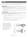
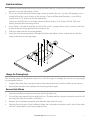
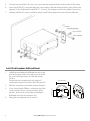
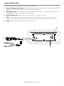
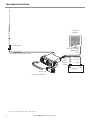
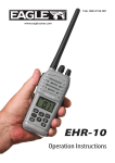
Pub. 988-0158-031
www.eaglesonar.com
EVR-100
VHF Radio
Operation Instructions
Copyright © 2007 Navico
All rights reserved.
Eagle® is a registered trademark of Navico
No part of this manual may be copied, reproduced, republished, transmitted or
distributed for any purpose, without prior written consent of Eagle Electronics.
Any unauthorized commercial distribution of this manual is strictly
prohibited.
Eagle Electronics may find it necessary to change or end our policies,
regulations, and special offers at any time. We reserve the right to do so without
notice. All features and specifications subject to change without notice. All
screens in this manual are simulated. On the cover: EVR-100 shown. Other
models covered in the manual are similar.
For free owner’s manuals and the most current information on this product, its
operation and accessories, visit our web site: www.eaglesonar.com
Eagle Electronics
P.O. Box 669
Catoosa, OK USA 74015
Printed in China.
!
CAUTION
!
Please read carefully before installation and use.
WARNING
IMPORTANT SAFETY INFORMATION
DANGER
! CAUTION
This is the safety alert symbol. It is used to alert you to potential personal
injury hazards, Obey all safety messages that follow this symbol to
avoidpossible injury or death.
!CAUTION
WARNING
WARNING indicates a potentially hazardous situation which, if not avoided,
could result in death or serious injury
!DANGER
CAUTION
CAUTION indicates a potentially hazardous situation which, if not avoided,
could result in minor or moderate injury.
WARNING
CAUTION
CAUTION used without the safety alert symbol indicates a potentially
hazardous situation which, if not avoided, may result in property
damage.
!
DANGER
Table of Contents
Introduction..............................................................................................................................................4
Installation...............................................................................................................................................5
Display.................................................................................................................................................... 11
Basic Operation and Key Functions........................................................................................................... 12
Radio Operation...................................................................................................................................... 14
Turning Your Radio On/Off. . . . . . . . . . . . . . . . . . . . . . . . . . . . . . . . . . . . . . . . . . . . . . . . . . . . . . . . . . . 14
Adjusting Squelch . . . . . . . . . . . . . . . . . . . . . . . . . . . . . . . . . . . . . . . . . . . . . . . . . . . . . . . . . . . . . . . . . . . 14
Selecting High/Low Power . . . . . . . . . . . . . . . . . . . . . . . . . . . . . . . . . . . . . . . . . . . . . . . . . . . . . . . . . . . 14
Selecting Channels . . . . . . . . . . . . . . . . . . . . . . . . . . . . . . . . . . . . . . . . . . . . . . . . . . . . . . . . . . . . . . . . . . 14
Transmitting and Receiving . . . . . . . . . . . . . . . . . . . . . . . . . . . . . . . . . . . . . . . . . . . . . . . . . . . . . . . . . . 14
Scanning Features . . . . . . . . . . . . . . . . . . . . . . . . . . . . . . . . . . . . . . . . . . . . . . . . . . . . . . . . . . . . . . . . . . . 15
Monitor Modes (Dual Watch). . . . . . . . . . . . . . . . . . . . . . . . . . . . . . . . . . . . . . . . . . . . . . . . . . . . . . . . . 15
NOAA Weather Channels. . . . . . . . . . . . . . . . . . . . . . . . . . . . . . . . . . . . . . . . . . . . . . . . . . . . . . . . . . . . . 16
NOAA Weather Alert. . . . . . . . . . . . . . . . . . . . . . . . . . . . . . . . . . . . . . . . . . . . . . . . . . . . . . . . . . . . . . . . . 16
Resetting your Radio . . . . . . . . . . . . . . . . . . . . . . . . . . . . . . . . . . . . . . . . . . . . . . . . . . . . . . . . . . . . . . . . . 16
Appendix A - Technical Specifications....................................................................................................... 17
Appendix B - Troubleshooting.................................................................................................................. 18
Appendix C - Frequency Charts................................................................................................................. 19
International Channel Chart. . . . . . . . . . . . . . . . . . . . . . . . . . . . . . . . . . . . . . . . . . . . . . . . . . . . . . . . . . 19
USA Channel Chart. . . . . . . . . . . . . . . . . . . . . . . . . . . . . . . . . . . . . . . . . . . . . . . . . . . . . . . . . . . . . . . . . . . 21
CANADA Channel Chart. . . . . . . . . . . . . . . . . . . . . . . . . . . . . . . . . . . . . . . . . . . . . . . . . . . . . . . . . . . . . . 23
WEATHER Channels. . . . . . . . . . . . . . . . . . . . . . . . . . . . . . . . . . . . . . . . . . . . . . . . . . . . . . . . . . . . . . . . . . 25
Eagle Warranty........................................................................................................................................ 26
How to Obtain Service . . ......................................................................................................................... 27
EAGLE EVR-100 Operation Instructions
3
Introduction :
Congratulations on your purchase of an Eagle EVR-100 marine band VHF radio. Designed for
international operation, allows you to transmit and receive on all international channels in the
VHF marine band, as assigned by the International Union (ITU). The EVR-100 is approved with
commercial-grade standards to give you clear, reliable communication.
NOTE: According to WEEE regulations, the user should not dispose the product when damaged,
but rather send it back to Eagle for disposal. Refer to How to Obtain Service section for
instructions to contact Eagle.
Your radio has the following features:
l
ſ Prominent channel display
Keypad and LCD backlighting for easy night-time use
l
Waterproof and submersible to comply with JIS-7
l
Choice of High or Low (7 W or 1 W) transmission power
l
Top centered PTT button for comfortable left- or right-handed use
l
Powerful 4 W external audio output
l
Access to all currently-available marine VHF channel bands (USA, Canada, International)
including Weather channels where available
l
Special CH16/9 key for quick access to the priority (international distress) channel
l
Special 3CH key to select your three favorite channels
l
Weather alert facility where available
l
Squelch Adjustment to help eliminate noise between transmissions
l
Battery Level - displays the battery voltage
l
4
EAGLE EVR-100 Operation Instructions
Installation:
This Eagle radio allows you to make a maritime distress call to facilitate search and rescue. To
be effective as a safety device, this radio must be used only within the geographic range of a
shore-based VHF marine Channel 16 distress and safety watch system. The geographic range
may vary but under normal conditions is approximately 20 nautical miles.
Installation Options
There are two ways to install the radio. You can choose:
• a deck or overhead mounted gimbal installation. The reversible mounting gimbal is fixed to to a
suitable site and the radio is placed into it. The radio can be removed for storage and the viewing
angle can be adjusted.
•
a recessed installation. The radio is recessed into a cavity cut into a bulkhead. The radio fixture is
permanent and the viewing angle cannot be adjusted.
Location Requirements
Please check these BEFORE doing any cutting or drilling.
Whichever installation method you choose, ensure that the chosen location:
• is at least 3' (1 m) from the antenna
• allows easy connection to (at least) a 10 Amp fused 13.6 V DC electrical source and the
antenna
• is at least 1.5' (45 cms) from the compass to avoid creating magnetic deviation of the compass
during radio operation
• has a suitable space close by for installing the microphone bulkhead mount
• provides easy access to the controls on the front panel
• provides reasonable access to the wiring at the back of the radio
The VHF has a large LCD screen
with an optimum viewing angle
of approx. +/-20 deg. Ensure the
chosen location provides a suitable
view of the display. Ideally, the user
should be directly in front of the
display or no more than +/-20 deg
from the front of the display.
Note: If unsure, temporarily power
up the radio and check for a
suitable location.
Side
20˚
20˚
Top
20˚
20˚
EAGLE EVR-100 Operation Instructions
5
Checklist
The following items should be supplied in the box. Check before starting the installation and contact your dealer if an item is missing.
NOTE: An antenna is NOT provided. Consult your Eagle dealer for advice if necessary.
1.
2.
Mounting gimbal for the VHF radio
Power supply cable with inbuilt 3 Amp
fuse
3. External speaker connection cable with
white (+) wire and black (-) wire
4. Two mounting knobs
5. Microphone bulkhead mount
6. Four self-tapping screws for the mounting
gimbal
7. Four flat screws for the mounting gimbal
8. Four spring washers for the mounting
gimbal
9. Four plain washers for the mounting
gimbal
10. Four nuts for the mounting gimbal
11. Two self-tapping screws for the
microphone bulkhead mount
12. Two flat screws for the microphone
bulkhead mount
1
13. Two spring washers for the microphone
bulkhead mount
14. Two plain washers for the microphone
bulkhead mount
15. Two nuts for the microphone bulkhead
mount
16. Two flush-mount brackets for recessed
installation
17. Two M5x32 screws for recessedinstallation
18. Two M5x10 screws for recessed installation
19. Two plastic stoppers for the recessed
installation (not pictured)
20. Installation template (not pictured)
21. One 3 Amp spare fuse (not pictured)
in case of accidental reverse of battery
polarity
22. Base unit and microphone (not pictured)
4
5
6
7
8
9
10
2
3
17 & 18
11
12
16
13
14
15
6
EAGLE EVR-100 Operation Instructions
Gimbal Installation
1.
Hold the mounting gimbal at the chosen location and use a soft pencil to mark the screw hole
positions onto the mounting surface.
2.
If you can’t reach behind the mounting surface to attach the nuts, use the self-tapping screws
instead of the flat screws shown in the picture. If you’re drilling into fiberglass, use a drill bit
smaller than 3/16” (5mm) to drill the pilot holes.
Otherwise, drill the four screw holes where marked, using a 3/16” (5mm) drill bit. Drill completely through the mounting surface.
3.
Use a Philips screwdriver and the set of four flat screws, spring washers, plain washers, and nuts
to attach the mounting gimbal to the location site.
4.
Slide the radio into the mounting gimbal.
5.
Insert the two mounting knobs through the holes and tighten them sufficiently to hold the
radio at the desired viewing angle.
Change the Viewing Angle
The viewing angle on the gimbal mount has a 20º tilt range. To change the current viewing angle
on the gimbal mount:
1. Support the radio, then cautiously loosen the mounting knobs until the radio can be moved.
2.
Re-position the radio then tighten the mounting knobs again.
Recessed Installation
1.
Tape the installation template onto the chosen location site.
2.
Cut out the area marked by the solid dark line. (The dashed line indicates the total area that will
be ed by the radio fascia after installation.)
3.
Remove the installation template and slide the radio into the cavity.
4.
Working from the rear of the bulkhead, align the racheted outstand on each side of the radio
with the central hole in each mounting bracket.
EAGLE EVR-100 Operation Instructions
7
5.
Use the two short M5x10 screws to screw the mounting brackets to the sides of the radio.
6.
Screw each M5x32 screw through the screw hole in the mounting bracket, then attach the
stopper. If your bulkhead exceeds 0.51” (13mm), the stopper can be discarded if necessary.
7.
Tighten the M5x32 screws until the radio is held firmly against the rear of the bulkhead.
Install the Microphone Bulkhead Mount
Hold the microphone bulkhead mount at the
chosen location and use a soft pencil to mark
the screw hole positions on the mounting
surface.
Ensure that the microphone curly cable will
comfortably reach this location BEFORE you drill.
4.
Hang the microphone on its mount.
8
EAGLE EVR-100 Operation Instructions
MM
Use a short length Philips screwdriver and the
set of two flat screws, spring washers, plain
washers, and nuts to secure the microphone
bulkhead mount at the location site.
MM
Drill the two pilot screw holes where marked.
3.
MM
2.
MM
MM
MM
1.
Connect the Radio Cables
The connectors are on the rear of the base unit, as follows:
1. External Speaker connector. Plug the external speaker cable jack into the connector BEFORE
powering on the radio. Use a 4 Ohm 4 Watt external speaker.
2.
RED Power wire. Connect this to the POSITIVE (+) battery terminal. Check that a 3 Amp fuse is
installed on this power cable close to the battery.
3.
BLACK Power wire. Connect this to the NEGATIVE (-) battery terminal.
4.
ANT. A radio antenna is not supplied. A suitable radio antenna must be mounted and
connected before operating the EVR-100 radio. Consult your dealer for advice if necessary.
5.
GND. A ground connection is not usually required.
4
1
2
5
3
EAGLE EVR-100 Operation Instructions
9
The Completed Installation
External
speaker
VHF Antenna
External speaker
connection
cable
Antenna connection cable
Fuse
on RED
power
cable
BLACK
power
cable
Battery
Base unit
with microphone*
* Actual model may differ from that shown
10
EAGLE EVR-100 Operation Instructions
Display
LCD symbols and Meanings
Symbol Meaning
Transmitting. TX HI LO
Transmission power. High (HI) 7W or Low (LO) 1W.
BUSY Receiver busy with an incoming signal.
WX
Weather channel.
WX ALT
Weather Alert. Alarm beeps will sound.
PRI
Priority channel is selected.
SCAN
Scanning channels.
DW
Dual Watch mode.
ALL
ALL channels scan mode.
C1 C2 C3
Shows which of the 3 favourite channels, if any, are selected, otherwise
blank.
(small)
(large)
Channel selected.
UIC
Selected Channel bank for VHF radio operations and regulations (USA,
International, Canada)
Low Battery warning (activates at 10.5V)
Channel is temporarily deleted from the ALL SCAN operation. D Indicates
a Duplex channel is selected, otherwise, blank for Simplex operation.
A B
Channel suffix, if applicable.
D
Duplex operation, otherwise, blank for simplex operation.
EAGLE EVR-100 Operation Instructions
11
Basic Operation and Key Functions
Key
VOL/PWR
SQL
16/9
WX
UIC
3CH +/-
12
Function
Volume and Power. Turn clockwise to power on. Continue to turn until a
comfortable volume is reached. VOL/PWR will also adjust the settings of an external
speaker, if connected
Squelch or Threshold Level. Sets the threshold level for the minimum receiver
signal. Turn fully counterclockwise until random noise is heard, then turn slowly
clockwise until the random noise disappears. Make another 1/4 turn clockwise for
best reception in open sea conditions.
Priority Channel. Also on the microphone. Press to cancel all other modes and to
tune into the priority channel. Press again to return to your original channel.
The default is Channel 16. To make Channel 09 the priority channel, hold down 16/9
until a beep sounds and 09 is displayed.
Weather Channel. In USA and Canadian waters, press to hear the most recently
selected weather station. The WX symbol is displayed on the LCD.
Press + CH - to change to a different weather channel. Press WX again to return to
the most recent channel.
If the weather alert mode (ALT) is ON and an alert tone of 1050Hz is broadcast from
the weather station, it is picked up automatically and the alarm sounds. Press any key
to hear the weather alert voice message.
Channel Bank. Press to toggle between USA, International or Canadian channel
banks. The selected channel bank is displayed on the LCD along with the last used
channel. All the channel charts are shown in Appendix.
Three Favourite Channels. Also on the microphone. Press to toggle between your
favourite channels. The C1, C2, or C3 symbol appears on the LCD to show which
favourite channel is selected.
EAGLE EVR-100 Operation Instructions
SCAN
+ CH -
SKIP
H/L
PTT
To scan only one of your favourite channels, press 3CH then immediately press
and release SCAN. If you want to scan all three favourite channels, press 3CH then
immediately press and hold SCAN.
To add a favourite channel for the first time, select that channel then hold 3CH
to store it in the CH1 location. Repeat the procedure to store two more favourite
channels in the CH2 and CH3 locations respectively.
If you try and add another favourite channel it will overwrite the existing CH1. CH2
and CH3 remain unless you delete them.
To delete a favourite channel, select that channel then hold down 3CH until the C1,
C2 or C3 symbol disappears on the LCD.
Scan. Press to scan between your current channel and the priority channel in DUAL
WATCH mode. The weather channel is also scanned if the weather alert mode (ALT)
is ON.
Hold down SCAN to enter ALL SCAN mode where the priority channel is checked
every 1.5 seconds.
When a signal is received, scanning stops at that channel and BUSY appears on the
screen. If the signal ceases for more than 3 seconds, the scan restarts.
Press SKIP to temporarily skip over an “always busy” channel when in ALL SCAN
mode and resume the scan. An
is shown on the screen to designate a skipped
channel. Note that it is not possible to skip over the priority channel.
Press SCAN again to stop at the current channel.
Channel Select. Also on the microphone. The current channel is shown on the
screen in BIG digits with an appropriate designator suffix A or B in small letters below
the channel number.
Press + CH - to step through the available channels one at a time, or hold down to
scroll rapidly through all the available channels. See Appendix for a listing of channel
charts.
Backlight switch. Press to turn on the backlighting, press again to turn off
Battery Level Check. Press to display the battery voltage level. The battery voltage
level will be displayed for 5 seconds before returning back to the previous screen.
Remove from ALL scan. Press to temporarily remove (SKIP) the channel from ALL
SCAN. The channel will be marked with an . Press again to cancel the channel
SKIP.
Transmission Power. On the microphone ONLY. High (HI) 7W or Low (LO) 1W. Press
to toggle between high or low transmission power for the entire channel bank. The
HI or LO selection is shown on the LCD.
Some channels allow only low power transmissions. Error beeps will sound if the
power transmission setting is incorrect.
Some channels allow only low power transmissions initially, but can be changed
to high power by holding down H/L and PTT at the same time. See Appendix for a
complete listing of channel charts.
Push To Talk. On the microphone ONLY. Push to start transmitting.
EAGLE EVR-100 Operation Instructions
13
Radio Operation
Turning Your Radio On/Off
Rotate VOL/PWR knob to turn the radio on or off. Rotate to adjust the volume to a comfortable
level.
Adjusting Squelch
Squelch is used to eliminate static and background noise and allows for silent operation of your
radio until a transmission is received. If the squelch is too high, only the strongest transmissions
can be heard, and when too low, intermittent static and noise are heard.
To set Squelch:
1. Turn SQL knob fully counter-clockwise. You will hear a lot of static noise.
2. Then turn SQL knob clockwise slowely until the static noise stops, this is the correct position
for the SQL knob.
Selecting High/Low Power
Press and release the H/L key on the microphone to toggle the transmit power between high and
low. When the unit is operating at low power, “Lo” appears on LCD and “Hi” appears on LCD when
operating at high power.
Some channels allow only low power transmissions. Error beeps will sound if the power
transmission setting is incorrect. Some channels allow only low power transmissions initially, but
can be changed to high power by holding down H/L and PTT at the same time. See Appendix for
a complete listing of channel charts.
Selecting Channels
To select a channel:
Use the + CH - key to find a channel. Stop when you find the desired channel.
NOTE: Not all channel numbers are available in INT bands, see marine Channel charts at the back
of this manual.
Transmitting and Receiving
Press and hold the Push-To-Talk (PTT) key to transmit on the selected channel, then release to
receive. The TX indicator appears while transmitting.
14
EAGLE EVR-100 Operation Instructions
Scanning Features
Your radio is equipped with 2 types of scan options: All Scan, 3CH Scan (Favourite Channel
Scan). If there are no channels added as favourite channels, the default is All Scan. This function
automatically searches for transmissions on the channel being scanned. If a signal is received, the
scan stops on the receiving channel as long as it is present and the SCAN indicator flashes. If the
signal is lost for 3 seconds, the radio resumes scanning.
All Scan
Press and hold the SCAN key for 3 seconds to activate the All Scan function. The SCAN and ALL
indicator appears on the LCD during All Scan. In All Scan mode, all channels in the channel set are
scanned in sequence except the channel set as SKIP channel using SKIP function. After the last
channel number has been scanned, the cycle repeats. Press SCAN key again to terminate the
SCAN mode.
To Skip a channel in ALL scan
Press SKIP to temporarily remove (SKIP) the channel from ALL SCAN. The channel will be marked with an . Press again to cancel the channel SKIP.
3CH Scan (Favourite Channels Scan)
Press 3CH key when there is at least one favourite channel saved in memory.
Press and hold the SCAN key for 3 seconds to start 3CH Scan , the SCAN indicators appear on the
LCD. Only the favourite channels and priority channels (CH16) are scanned in sequence.
Your radio can store up to three favourite channels. Quick press of the 3CH key will access the
stored favourite channels directly (shortcut).
To Add Channels to 3CH List
During normal operation mode, use the + CH - keys to select the desired channel for
programming.
Press and hold the 3CH key for 3 seconds. The "C1" icon appears to indicate the current
channel has been saved in first favourite channel. Repeat for the second and third favourite
channels as C2 and C3 respectively.
To Delete Channels from 3CH List
Select the favourite channel to be deleted using the + CH - keys, or repeated quick press of
the 3CH key. Press and hold the 3CH key until the “Cn” icon disappears.
Monitor Modes (Dual Watch)
Quick press the SCAN key to activate the Dual Watch mode. The "DW" indicator appears on the
LCD. Dual Watch monitors the current working channel and Channel 16 in sequence. WX ALT is
also scanned in this mode if set. The watch is halted when activity is detected on a monitored
channel. Press SCAN key or PTT to terminate Dual Watch and return to the previous working
channel.
EAGLE EVR-100 Operation Instructions
15
NOAA Weather Channels
To receive a NOAA (National Oceanic and Atmospheric Administration) weather channel, press the
WX key. The transceiver will go to the last selected weather channel.
Press the + CH - keys to scroll through the available WX channels.
To exit from the NOAA weather channels, press the WX key to terminate WX mode and return to
the previous working channel, or press 16/9 to access the priority channels.
NOAA Weather Alert
In the event of extreme weather disturbances, such as storms and hurricanes, the NOAA sends
a weather alert accompanied by a 1050 Hz tone and subsequent weather report on one of the
NOAA weather channels.
When the Weather Alert feature is enabled, your radio is capable of receiving this alert.
In the Weather channel, press and hold WX button for 3 seconds to active the Alert function “ALT” will appear on the LCD. To cancel the alert function, Press and hold WX button for 3 seconds
again, the “ALT” icon will disappear from the LCD.
Note: If Weather Alert mode is selected (WX ALT icon displayed in WX mode), Weather Alert will
continue to be monitored even when in normal mode (non-Wx channels) is selected.
Resetting your Radio
Your radio can be reset to factory defaults. A factory reset clears the following user settings:
l ſ favourite channels,
l ſ current channel,
l ſ channel bank.
To perform the reset:
1. Turn the radio OFF.
2. Simultaneously press and hold the SCAN & UIC buttons.
3. Continue to hold the keys until “CC” appears on the LCD. Release the keys to finish the reset
process. The LCD switches to CH16 and USA channel bank is selected..
16
EAGLE EVR-100 Operation Instructions
Appendix A - Technical Specifications
GENERAL
Power Supply:
13.8V DC.
Current drain:
Transmit
1.5 A at 7 W Tx / 0.6A at 1W Tx
Receive
Less than 250mA in standby
Useable channels:
International, USA, Canada, Weather (country specific)
Mode:
16K0G3E (FM)
PHYSICAL
LCD display (viewing):
41(H) x 53(W) mm
Backlight control:
Yes (On/Off )
Antenna connector:
SO-239 (50 ohm)
Temperature Range:
-17ºC to +50ºC
Waterproof:
JIS-7
Dimensions:
161(W) x 75(H) x 147(D) mm - without bracket
Weight:
0.87kg with microphone
Frequency stability:
+/- 10ppm
Frequency control:
PLL
GPS/NMEA input:
No
Comm port:
n/a
DSC:
No
FEATURES
Flush Mount kit:
Yes
Local/Distant control:
No
Position polling:
No
Group Call:
No
Channel Naming:
No
Dual watch, Favourite
channel scan, All scan:
Yes
TRANSMITTER
Frequency:
156.025 - 157.425MHz
Output power:
7 W / 1 W selectable
Transmitter protection:
Open / short circuit of antenna
Max Freq deviation:
+/- 5kHz
Spurious & harmonics:
better than 2.5µ W
Modulation distortion:
Less than 4%@ 1kHz for a +/-3kHz deviation RECEIVER
Frequency:
156.025 - 163.275 MHz
12dB SINAD sensitivity:
0.25uV
20db SINAD sensitivity:
0.35uV
Adjacent CH selectivity:
more than 65db
Spurious response:
more than 65 db
Intermodulation Rejection ratio:
more than 65 db
Residual Noise level:
more than -40 db unsquelched
Audio output power:
2 W (with 8 ohm at 10% distortion)
4 W with 4 ohm external speaker
Compass safe distance:
0.5 m (1.5’)
Specifications are subject to change without notice.
EAGLE EVR-100 Operation Instructions
17
Appendix B - Troubleshooting
1. The transceiver will not power up.
A fuse may have blown OR there is no voltage getting to the transceiver.
a) Check the power cable for cuts, breaks, or squashed sections.
b) After checking the wiring, replace the 3 Amp fuse (1 spare fuse is supplied).
c) Check the battery voltage. This must be greater than 10.5V.
2. The transceiver blows the fuse when the power is switched on.
The power wires may have been reversed.
a) Check that the red wire is connected to the positive battery terminal, and the black wire is
connected to the negative battery terminal.
3. The speaker makes popping or whining noises when the engine is running.
Electrical noise may be interfering with the transceiver.
a) Re-route the power cables away from the engine.
b) Add a noise suppressor to the power cable.
c) Use resistive spark plug wires and/or use an alternator whine filter
4. No sound from the external speaker.
a) Check that the external speaker cable is physically connected.
b) Check the soldering of the external speaker cable.
5. Transmissions are always on low power, even when high (HI) power is selected.
The antenna may be faulty.
a) Test the transceiver with a different antenna.
b) Have the antenna checked out.
6. Battery symbol is displayed.
The power supply is too low or too high.
a) Check the battery voltage. This should be at least 10.5V ± 0.5V DC.
b) Check the alternator on the vessel.
18
EAGLE EVR-100 Operation Instructions
Appendix C - Frequency Charts
International Channel Chart
CH
TX
RX
MODE TRAFFIC TYPE
(MHz) (MHz)
01 156.050 160.650
D Public Correspondence
02 156.100 160.700
D Public Correspondence
03 156.150 160.750
D Public Correspondence
04 156.200 160.800
D Port Operations
05 156.250 160.850
D Port Operations, Selected VTS Areas
06 156.300 156.300
S
Inter-ship Safety
07 156.350 160.950
D Port Operations
08 156.400 156.400
S
Commercial (inter-ship only)
09 156.450 156.450
S
Recreational Calling Channel
10 156.500 156.500
S
Commercial
11 156.550 156.550
S
Commercial, VTS in Selected Areas
12 156.600 156.600
S
Port Operations, Selected VTS Areas
Inter-ship Navigation Safety (bridge-to bridge)
13 156.650 156.650
S
14 156.700 156.700
S
Port Operations, Selected VTS Areas
15 156.750 156.750
S
Port Operations
16 156.800 156.800
S
International Distress, Safety, and Calling
17 156.850 156.850
S
State Controlled
18 156.900 161.500
D Port Operations
19 156.950 161.550
D Commercial
20 157.000 161.600
D Port Operations
21 157.050 161.650
D Port Operations
22 157.100 161.700
D Port Operations
23 157.150 161.750
D Public Correspondence
24 157.200 161.800
D Public Correspondence
25 157.250 161.850
D Public Correspondence
26 157.300 161.900
D Public Correspondence
27 157.350 161.950
D Public Correspondence
28 157.400 162.000
D Public Correspondence
60 156.025 160.625
D Public Correspondence
61 156.075 160.675
D Port Operations
62 156.125 160.725
D Port Operations
63 156.175 160.775
D Port Operations
64 156.225 160.825
D Public Correspondence
65 156.275 160.875
D Port Operations
EAGLE EVR-100 Operation Instructions
SHIP
TO
SHIP
No
No
No
No
No
Yes
No
Yes
Yes
Yes
Yes
Yes
Yes
Yes
Yes
Yes
Yes
No
No
No
No
No
No
No
No
No
No
No
No
No
No
No
No
No
SHIP
REMARK
TO
SHORE
Yes
Yes
Yes
Yes
Yes
No
Yes
No
Yes
Yes
Yes
Yes
No
Yes
1 1W only
Yes
Yes
1 1W only
Yes
Yes
Yes
Yes
Yes
Yes
Yes
Yes
Yes
Yes
Yes
Yes
Yes
Yes
Yes
Yes
Yes
Yes
19
66
67
68
69
70
71
72
73
74
77
78
79
80
81
82
83
84
85
86
87
88
156.325
156.375
156.425
156.475
156.525
156.575
156.625
156.675
156.725
156.875
156.925
156.975
157.025
157.075
157.125
157.175
157.225
157.275
157.325
157.375
157.425
160.925 D
156.375 S
156.425 S
156.475 S
156.525
156.575 S
156.625 S
156.675 S
156.725 S
156.875 S
161.525 D
161.575 D
161.625 D
161.675 D
161.725 D
161.775 D
161.825 D
161.875 D
161.925 D
161.975 D
162.025 D
Port Operations
Commercial, bridge-to-bridge
Boat Operations, Recreational
Port Operations
Digital Selective Calling - DSC
Port Operations
Inter-ship
Port Operations
Port Operations
Inter-ship
Non-Commercial
Commercial
Commercial
Port Operations
Port Operations
Public Correspondence
Public Correspondence
Public Correspondence
Public Correspondence
Public Correspondence
Public Correspondence
No
Yes
Yes
Yes
------
Yes
Yes
Yes
Yes
Yes
No
No
No
No
No
No
No
No
No
No
No
Yes
No
No
Yes
2
------
Yes
No
Yes
Yes
No
Yes
Yes
Yes
Yes
Yes
Yes
Yes
Yes
Yes
Yes
Yes
Special Notes on International Channel Usage
. LOW POWER (1W) only.
. Channel 70 is designated for use exclusively for Digital Selective Calling (DSC), such as Distress,
Safety, and Ship Calls. No voice communication is allowed on CH70. This channel is only available
on DSC enabled radios.
1
2
Note: The INTERNATIONAL mode is not legal for use in U.S. or Canada waters.
KEY: S = Simplex operating channel; D = Duplex operating channel.
20
EAGLE EVR-100 Operation Instructions
USA Channel Chart
CH
TX
RX
MODE TRAFFIC TYPE
(MHz) (MHz)
01A 156.050 156.050
S
Port Operations, Selected VTS Areas
03A 156.150 156.150
S
US Government, Coast Guard
05A 156.250 156.250
S
Port Operations, Selected VTS Areas
06 156.300 156.300
S
Inter-ship Safety
07A 156.350 156.350
S
Commercial
08 156.400 156.400
S
Commercial (inter-ship only)
09 156.450 156.450
S
Recreational Calling Channel
10 156.500 156.500
S
Commercial
11 156.550 156.550
S
Commercial, VTS in Selected Areas
12 156.600 156.600
S
Port Operations, Selected VTS Areas
13 156.650 156.650
S
Inter-ship Navigation Safety (bridge-to bridge),
1W with Power-up
14 156.700 156.700
S
Port Operations, Selected VTS Areas
15
---
156.750
S
Environmental
16 156.800 156.800
S
International Distress, Safety, and Calling
17 156.850 156.850
S
State Controlled
18A 156.900 156.900
S
Commercial
19A 156.950 156.950
S
Commercial
20 157.000 161.600 D Port Operations, Canadian Coast Guard
20A 157.000 157.000
S
Port Operations
21A 157.050 157.050
S
U.S. Government, Canadian Coast Guard
22A 157.100 157.100
S
Coast Guard Liaison
23A 157.150 157.150
S
U.S. Government, Coast Guard
24 157.200 161.800 D Public Correspondence, Marine operator
25 157.250 161.850 D Public Correspondence, Marine operator
26 157.300 161.900 D Public Correspondence, Marine operator
27 157.350 161.950 D Public Correspondence, Marine operator
28 157.400 162.000 D Public Correspondence, Marine operator
61A 156.075 156.075
S
U.S. Government, Canadian Coast Guard
63A 156.175 156.175
S
Port Operations, VTS in Selected Areas
U.S. Government, Canadian Commercial Fishing
64A 156.225 156.225
S
65A 156.275 156.275
S
Port Operations
66A 156.325 156.325
S
Port Operations
Commercial, bridge-to-bridge, 1W with Power-up
67 156.375 156.375
S
EAGLE EVR-100 Operation Instructions
SHIP
TO
SHIP
Yes
Yes
Yes
Yes
Yes
Yes
Yes
Yes
Yes
Yes
Yes
SHIP
REMARK
TO
SHORE
Yes
4
Yes
Yes
No
Yes
No
Yes
Yes
Yes
Yes
3 1W
No
Yes
------
Yes
Yes
Yes
Yes
No
Yes
Yes
Yes
Yes
No
No
No
No
No
Yes
Yes
Yes
Yes
Yes
Yes
Yes
2 RX only
------
Yes
1 1W only
Yes
Yes
Yes
Yes
Yes
4
Yes
Yes
4
Yes
Yes
Yes
Yes
Yes
Yes
4
Yes
Yes
4
Yes
Yes
Yes
3 1W
No
21
68 156.425 156.425
S
69 156.475 156.475
S
70 156.525 156.525
71 156.575 156.575
S
72 156.625 156.625
S
73 156.675 156.675
S
74 156.725 156.725
S
77 156.875 156.875
S
78A 156.925 156.925
S
79A 156.975 156.975
S
80A 157.025 157.025
S
81A 157.075 157.075
S
82A 157.125 157.125
S
83A 157.175 157.175
S
84 157.225 161.825 D
85 157.275 161.875 D
86 157.325 161.925 D
87 157.375 161.975 D
88 157.425 162.025 D
88A 157.425 157.425
S
Boat Operations, Recreational
Boat Operations, Recreational
Digital Selective Calling - DSC
Boat Operations, Recreational
Boat Operations, Recreational
Port Operations
Port Operations
Port Operations
Boat Operations, Recreational
Commercial
Commercial
U.S. Government, Environmental Protection
Agency Operations
U.S. Government, Canadian Coast Guard
U.S. Government, Canadian Coast Guard
Public Correspondence, Marine Operator
Public Correspondence, Marine Operator
Public Correspondence, Marine Operator
Public Correspondence, Marine Operator
Public Correspondence, Marine Operator
Commercial, Inter-ship Only
Yes
Yes
------
Yes
Yes
Yes
Yes
Yes
Yes
Yes
Yes
Yes
No
Yes
6
------
Yes
No
Yes
Yes
1 1W only
Yes
No
Yes
Yes
4
Yes
Yes
Yes
No
No
No
No
No
Yes
4
Yes
4
Yes
Yes
Yes
Yes
Yes
Yes
No
Special Notes on USA Channel Usage
. LOW POWER (1 W) only.
. Receive Only.
3 . LOW POWER (1 W) initially. Override to HIGH POWER by holding down H/L key before
transmitting. Used normally in bridge-to-bridge communications.
4 . Lightly shaded simplex channels 03A, 21A, 23A, 61A, 64A, 81A, 82A, and 83A cannot be lawfully
used in U.S. waters unless special authorization is obtained from the U.S. Coast Guard. Not for use
by the general public.
5 . The letter “A” illuminated by the channel number indicates the USA channel is simplex.
This same channel is always duplex when selecting International. There is no “A” reference for
International channels. The letter “B” is only used for some Canadian “Receive only” channels.
6 . Channel 70 is designated for use exclusively for Digital Selective Calling (DSC), such as Distress,
Safety, and Ship Calls. No voice communication is allowed on CH70. This channel is only available
on DSC enabled radios.
1
2
KEY: S = Simplex operating channel; D = Duplex operating channel.
22
EAGLE EVR-100 Operation Instructions
CANADA Channel Chart
CH
TX
RX
(MHz) (MHz)
MODE
01 156.050 160.650
02 156.100 160.700
03 156.150 160.750
04A 156.200 156.200
05A 156.250 156.250
06 156.300 156.300
07A 156.350 156.350
08 156.400 156.400
09 156.450 156.450
10 156.500 156.500
11 156.550 156.550
12 156.600 156.600
13 156.650 156.650
14 156.700 156.700
15 156.750 156.750
16 156.800 156.800
17 156.850 156.850
18A 156.900 156.900
19A 156.950 156.950
20 157.000 161.600
21 157.050 161.650
21A 157.050 157.050
21B
---
161.650
22A 157.100 157.100
23 157.150 161.750
24 157.200 161.800
25 157.250 161.850
25B
---
161.850
26 157.300 161.900
27 157.350 161.950
28 157.400 162.000
28B
---
162.000
60 156.025 160.625
61A 156.075 156.075
62A 156.125 156.125
D
D
D
S
S
S
S
S
S
S
S
S
S
S
S
S
S
S
S
D
D
S
S
S
D
D
D
S
D
D
D
S
D
S
S
TRAFFIC TYPE
SHIP
TO
SHIP
SHIP
TO
SHORE
Public Correspondence
Public Correspondence
Public Correspondence
Canadian Coast Guard, SAR
Port Operations, VTS in Selected Areas
Inter-ship Safety
Commercial
Commercial (inter-ship only)
Recreational Calling Channel
Commercial
Commercial, VTS in Selected Areas
Port Operations, VTS in Selected Areas
Inter-ship Navigation Safety (bridge-to
bridge) 1W with power-up
Port Operations, VTS in Selected Areas
Commercial
International Distress, Safety, and Calling
State Controlled
Commercial
Canadian Coast Guard
Canadian Coast Guard
Port Operations
U.S. Government, Canadian Coast Guard
Port Operations
Canadian Coast Guard Liaison
Public Correspondence
Public Correspondence
Public Correspondence
Public Correspondence
Public Correspondence
Public Correspondence
Public Correspondence
Public Correspondence
Public Correspondence
U.S. Government, Canadian Coast Guard
Canadian Coast Guard
No
No
No
Yes
Yes
Yes
Yes
Yes
Yes
Yes
Yes
Yes
Yes
Yes
Yes
Yes
Yes
Yes
No
Yes
No
Yes
Yes
Yes
Yes
3 1W
No
Yes
Yes
Yes
Yes
Yes
Yes
No
No
Yes
------
Yes
No
No
No
------
No
No
No
------
No
Yes
Yes
Yes
1
Yes
Yes
1
Yes
Yes
Yes
1
Yes
Yes
Yes
2
------
Yes
Yes
Yes
Yes
2
------
Yes
Yes
Yes
2
------
Yes
4
Yes
Yes
EAGLE EVR-100 Operation Instructions
REMARK
1W only
1W only
1W only
RX only
RX only
RX only
23
64
64A
65A
66A
67
68
69
70
71
72
73
74
77
78A
79A
80A
81A
82A
83
83A
83B
84
85
86
87
88
156.225
156.225
156.275
156.325
156.375
156.425
156.475
156.525
156.575
156.625
156.675
156.725
156.875
156.925
156.975
157.025
157.075
157.125
157.175
157.175
---
157.225
157.275
157.325
157.375
157.425
160.825
156.225
156.275
156.325
156.375
156.425
156.475
156.525
156.575
156.625
156.675
156.725
156.875
156.925
156.975
157.025
157.075
157.125
161.775
157.175
161.775
161.825
161.875
161.925
161.975
162.025
D
S
S
S
S
S
S
S
S
S
S
S
S
S
S
S
S
D
S
S
D
D
D
D
D
Public Correspondence, Duplex
U.S. Government, Canadian Commercial Fishing
Port Operations
Port Operations
Commercial, SAR
Boat Operations, Recreational
Commercial Fishing Only
Digital Selective Calling - DSC
Boat Operations, Recreational
Inter-ship
Commercial Fishing Only
Commercial Fishing Only
Port Operations
Boat Operations, Recreational
Commercial
Commercial
U.S. Government Operations
U.S. Government, Canadian Coast Guard
Canadian Coast Guard
U.S. Government, Canadian Coast Guard
Canadian Coast Guard, RX Only
Public Correspondence, Marine Operator
Public Correspondence, Marine Operator
Public Correspondence, Marine Operator
Public Correspondence, Marine Operator
Public Correspondence, Marine Operator
No
Yes
Yes
Yes
Yes
Yes
Yes
------
Yes
Yes
Yes
Yes
Yes
Yes
Yes
Yes
Yes
Yes
Yes
Yes
------
No
No
No
No
No
Yes
4
Yes
Yes
1 1W only
Yes
No
No
Yes
6
------
Yes
No
Yes
Yes
1 1W only
Yes
No
Yes
Yes
4
Yes
4
Yes
Yes
4
Yes
2 RX only
------
Yes
Yes
Yes
Yes
Yes
Special Notes on Canada Channel Usage
. LOW POWER (1 W) only.
. Receive (RX) Only.
3 . LOW POWER (1 W) initially. Override to HIGH POWER by holding down H/L key before
transmitting. Used normally in bridge-to-bridge communications.
4 . Lightly shaded simplex channels 21A, 23A, 61A, 64A, 81A, 82A, and 83A cannot be lawfully used
in Canada waters unless special authorization is obtained from the Canadian Coast Guard. Not for
use by the general public.
5 . The letter “A” illuminated by the channel number indicates the Canada channel is simplex. This
same channel is always duplex when selecting International. There is no “A” reference for
International channels. The letter “B” is only used for some Canadian “Receive only” channels.
6 . Channel 70 is designated for use exclusively for Digital Selective Calling (DSC), such as Distress,
Safety, and Ship Calls. No voice communication is allowed on CH70. This channel is only available
on DSC enabled radios.
Note: The CANADA mode is not legal to use in U.S. waters.
KEY: S = Simplex operating channel; D = Duplex operating channel.
1
2
24
EAGLE EVR-100 Operation Instructions
WEATHER Channels
CH
WX01
WX02
WX03
WX04
WX05
WX06
WX07
WX08
WX09
WX10
RX
(MHz)
162.550
162.400
162.475
162.425
162.450
162.500
162.525
161.650
161.775
163.275
TRAFFIC TYPE
NAME
REMARK
NOAA Weather Channel
NOAA Weather Channel
NOAA Weather Channel
NOAA Weather Channel
NOAA Weather Channel
NOAA Weather Channel
NOAA Weather Channel
CANADIAN Weather Channel
CANADIAN Weather Channel
NOAA Weather Channel
NOAA WX
NOAA WX
NOAA WX
NOAA WX
NOAA WX
NOAA WX
NOAA WX
CANADA WX
CANADA WX
NOAA WX
RX only
RX only
RX only
RX only
RX only
RX only
RX only
RX only
RX only
RX only
EAGLE EVR-100 Operation Instructions
25
NAVICO
FULL TWO-YEAR EAGLE VHF WARRANTY
“We,” “our,” or “us” refers to NAVICO, the manufacturer of this EAGLE VHF product. “You” or “your”
refers to the first person who purchases this product as a consumer item for personal, family or
household use.
We warrant this product against defects or malfunctions in materials and workmanship, and
against failure to conform to this product’s written specifications, all for two (2) years from the
date of original purchase by you. Battery Packs and accessory items have a one (1) year warranty.
WE MAKE NO OTHER EXPRESS WARRANTY OR REPRESENTATION OF ANY KIND WHATSOEVER
CONCERNING THIS PRODUCT. Your remedies under this warranty will be available so long as you
can show in a reasonable manner that any defect or malfunction in materials or workmanship, or
any non-conformity with the product’s written specifications, occurred within two years from the
date of your original purchase, which must be substantiated by a dated sales receipt or sales slip.
Any such defect, malfunction, or non-conformity which occurs within two years from your original
purchase date will either be repaired without charge or be replaced with a new product identical
or reasonably equivalent to this product, at our option, within a reasonable time after our receipt of
the product. If such defect, malfunction, or non-conformity remains after a reasonable number of
attempts to repair by us, you may elect to obtain without charge a replacement of the product or
a refund for the product. THIS REPAIR, OR REPLACEMENT OR REFUND (AS JUST DESCRIBED) IS THE
EXCLUSIVE REMEDY AVAILABLE TO YOU AGAINST US FOR ANY DEFECT, MALFUNCTION, OR NONCONFORMITY CONCERNING THE PRODUCT OR FOR ANY LOSS OR DAMAGE RESULTING FROM ANY
OTHER CAUSE WHATSOEVER. WE WILL NOT UNDER ANY CIRCUMSTANCES BE LIABLE TO ANYONE
FOR ANY SPECIAL, CONSEQUENTIAL, INCIDENTAL, OR OTHER INDIRECT DAMAGE OF ANY KIND.
Some states do not allow the exclusion or limitation of incidental or consequential damages, so the
above limitations or exclusions may not apply to you.
This warranty does NOT apply in the following circumstances: (1) when the product has been
serviced or repaired by anyone other than us; (2) when the product has been connected, installed,
combined, altered, adjusted, or handled in a manner other than according to the instructions
furnished with the product; (3) when any serial number has been effaced, altered, or removed; or
(4) when any defect, problem, loss, or damage has resulted from any accident, misuse, negligence,
or carelessness, or from any failure to provide reasonable and necessary maintenance in accordance
with the instructions of the owner’s manual for the product.
We reserve the right to make changes or improvements in our products from time to time without
incurring the obligation to install such improvements or changes on equipment or items previously
manufactured.
This warranty gives you specific legal rights and you may also have other rights which may vary
from state to state.
REMINDER: You must retain the sales slip or sales receipt proving the date of your original purchase
in case warranty service is ever required.
NAVICO
12000 E. SKELLY DRIVE, TULSA, OK 74128
(800) 324-1356
26
EAGLE EVR-100 Operation Instructions
How to Obtain Service . . .
… in the USA:
We back your investment in quality products with quick, expert service and
genuine Eagle replacement parts. If you’re in the United States and you have
technical, return or repair questions, please contact the Factory Customer Service
Department. Before any product can be returned, you must call customer service
to determine if a return is necessary. Many times, customer service can resolve your
problem over the phone without sending your product to the factory. To call us,
use the following toll-free number:
800-324-1354
8 a.m. to 5 p.m. Central Standard Time, M-F
Eagle Electronics may find it necessary to change or end our shipping policies,
regulations, and special offers at any time. We reserve the right to do so without notice.
…in Canada:
If you’re in Canada and you have technical, return or repair questions, please
contact the Factory Customer Service Department. Before any product can be
returned, you must call customer service to determine if a return is necessary.
Many times, customer service can resolve your problem over the phone without
sending your product to the factory. To call us, use the following toll-free number:
800-661-3983
905-629-1614 (not toll-free)
8 a.m. to 5 p.m. Eastern Standard Time, M-F
…outside Canada and the USA:
If you have technical, return or repair questions, contact the dealer in the country
where you purchased your unit. To locate an Eagle dealer near you, visit our web
site or consult your telephone directory for listings.
www.eaglesonar.com
EAGLE EVR-100 Operation Instructions
27
Accessory Ordering Information for all countries
To order Eagle accessories such as power cables or transducers, please contact:
1) Your local marine dealer or consumer electronics store. Most quality dealers that handle
marine electronic equipment or other consumer electronics should be able to assist you
with these items.
To locate an Eagle dealer near you visit our web site or consult your telephone directory
for listings.
2) U.S. customers: LEI Extras Inc., PO Box 129, Catoosa, OK 74015-0129
Call 1-800-324-0045 or visit our web site www.lei-extras.com.
3) Canadian customers can write:
Lowrance/Eagle Canada, 919 Matheson Blvd. E. Mississauga, Ontario L4W2R7 or
fax 905-629-3118.
Shipping Information
If it becomes necessary to send a product for repair or replacement, you must first receive
a return authorization number from Customer Service. Products shipped without a return
authorization will not be accepted. When shipping, were commend you do the following:
1. Please do not ship the knobs or mounting bracket with your unit.
2. If you are sending a check for repair, please place your check in an envelopeand tape it to
the unit.
3. For proper testing, include a brief note with the product describing the problem. Be sure
to include your name, return shipping address and a day time telephone number. An
e-mail address is optional but useful.
4. Pack the unit in a suitable size box with packing material to prevent any damage during
shipping.
5. Write the Return Authorization (RA) number on the outside of the box underneath your
return address.
6. For your security, you may want to insure the package through your shipping courier.
Eagle does not assume responsibility for goods lost or damaged in transit.
28
EAGLE EVR-100 Operation Instructions
Notes:
Notes:
Notes:
Eagle Pub. 988-0158-031
Printed in China - 120107
MN000792A-G
Copyright © 2007
All Rights Reserved
Navico