1
4. Switcher Specifications
HOME & BUSINESS SECURITY
It’s all on the web
Switcher Specifications:
Channels
2
Scan Time
1~30 Seconds
Operating Voltage
12V DC 500mA
Camera Input
2 DIN
AV Output
1 DIN
Power Supply
DC 12V ± 10% 500mA
Operating Humidity
90% HM Max.
Operating Temp
14°F ~ 122°F
(-10°~ 50°C)
Product Information
Specification Sheets
User Manuals
Software Upgrades
Quick Start Guides
Firmware Upgrades
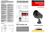
2 CHANNEL MINI
SWITCHER BOX
WITH 2 COLOR CAMERAS
Model: SHS-2SA
Please refer to the Camera Spec Sheets posted
online at http://www.lorexcctv.com for further
details on individual Camera Specifications.
Dimensions:
VISIT
www.lorexcctv.com
WARNING – REGULATED 12V DC 500mA power supply
REQUIRED for use with this Switcher. Use of a non-regulated,
non-conforming power supply can damage this product and will
void the warranty.
LOREX Technology Inc.
Copyright © 2007 LOREX Technology Inc. As our
products are subject to continuous improvement,
LOREX and its subsidiaries reserve the right to modify product design, specifications and prices, without
notice and without incurring any obligation. E&OE
Quick Set-up Guide
1. Package Contents
2. Switcher Controls
3. Camera Connections
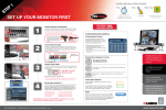
1. Connect the 65ft DIN Extension cable to the
Switcher. Run the cable as desired, and connect
the other end of the 65ft Extension Cable to the
DIN Camera (see Setup Diagram below).
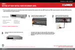
1 x Mini Switcher Box
NOTE: Cameras with 6 Pin DIN
connections draw power from the
Switcher. Additional power adaptors
are not needed for these cameras.
1 x Power Adaptor
1 x AV Cable
1 x Velcro Adhesive
Strip
2 x DIN Cameras*
2 x Camera Stands
2 x 65’ DIN Extension
Cables
* Cameras may not be exactly as shown.
Features:
1
2
3
1. SCAN TIME SETTING - Turn to adjust the Scan
Time between cameras (when in SCAN View Mode)
from 1~30 Seconds.
2. CHANNEL SELECT - Move the switch to change
the onscreen view to CH1, CH2 or SCAN View Mode.
3. STATUS INDICATOR LEDs - The Red LED light
indicates the state of the switcher: CH1, CH2 or
SCAN Mode.
4. DC POWER PORT - Connection port for the Power
Adaptor.
5. CH1~CH2 DIN PORTS - Receives the audio and
video signal from the Cameras.
6. A/V OUT DIN PORT - Sends the outgoing video/
audio signal to a TV or VCR.
• Easily connects to any TV, VCR or
Monitor
• Compact design
• Easy mounting with Velcro strip
(included)
2. Attach the camera to the supplied stand. Mount
the camera stand to the desired mounting surface
NOTE: Confirm that the arrows on the DIN
Extension cable are aligned with the Camera
Cable and Observation system ports when
connecting the cable. If the pins in the DIN
Cable are bent, the Camera will NOT
function
3. Connect the DIN end of the A/V Cable to the
switcher. Connect the RCA end to the
corresponding color ports on the TV or VCR:
•Yellow Cable: RCA Video
•White Cable: RCA Audio
4. Connect the Power Adapter to the switcher.
Setup Diagram:
Note:
Test the cameras prior to selecting a permanent
mounting location by temporarily connecting the
Cameras and Cables to the switcher.
4
5
6
* Cameras may not be exactly as shown.