1
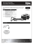
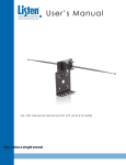
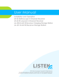
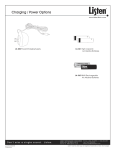
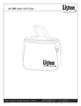
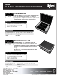
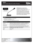
User’s Manual
LA-122 Universal Remote Antenna Kit
Listen Technologies Corporation
8535 South 700 West, Suite A
Sandy, Utah 84070-2515 USA
Telephone: +1.801.233.8992
Toll-Free (USA): 1.800.330.0891
Fax: +1.801.233.8995
E-mail: [email protected]
V.020603. Listen and the Listen logo are registered trademarks of Listen Technologies Corporation. Document #LM-122
Copyright © 2002 Listen Technologies Corporation. All Rights Reserved.
1
R
LA-122 Universal Antenna Kit
w w w. L i s t e n Te c h . c o m
Mounting Options:
Wall Mount (to your electrical box)
Direct Wall Mount
Ceiling Mount
In-Wall or In-Ceiling Mount
Mast Mount
F
E
D
B
A
C
Use With:
LT-800-072 Stationary Transmitter
LT-800-216 Stationary Transmitter
LR-100-072 Stationary Receiver /
Power Amplifier
LR-100-216 Stationary Receiver /
Power Amplifier
Kit Includes:
Optional Accessories
LA-315 Wireless Speaker / Portable
Antenna Stand
LA-127 RG58 BNC Cable Connector
LA-128 RG8 BNC Cable Connector
LA-112 RG58 Coaxial Cable
LA-113 RG8 Low Loss Coaxial Cable
LA-114 Coaxial Connector Installation
(2 connectors)
LA-121 BNC Adapter (LT-800-072 only)
A. Wall / Electrical Box Mounting Plate
B. Mounting Bracket
C. Antenna Module and 25 feet (7.6 m) RG58 coaxial cable
with BNC connectors
D. Telescoping antennas (2 for both 72 and 216 MHz)
E. Flexible antennas (2 for both 72 and 216 MHz)
F. Ground Plane and Shorting Plate
G. Mounting Hardware (not shown):
(4) #6-32 Machine Screws - used to mount to a single or
dual gang duplex box
(4) #8-32 Machine Screws - used to mount to a square or
hex junction or light box
(4) #8 Sheet Metal Screws - used to mount to metal or
wood, or for use with dry anchors
(4) Dry Anchors - used to mount to drywall, concrete,
plaster, brick, or masonry
(2) Hex Kep Nuts (#10-32) and (1) Fiber Washer - used for
mounting flexible antennas to the Antenna Module, and
for grounding purposes
Thank you for purchasing this Listen product! If you have any questions or would like
to offer suggestions on future Listen products, please contact us at the address shown
below.
LISTEN TECHNOLOGIES CORPORATION 8535 South 700 West, Suite A Sandy, Utah 84070-2515 USA
Phone: +1.801.233.8992 USA Toll Free: 1.800.330.0891 Fax:+1.801.233.8995 e-mail: [email protected]
2
R
LA-122 Universal Antenna Kit
w w w. L i s t e n Te c h . c o m
Table of Contents
Contents of Kit ...............................................................................
Specifications ................................................................................
Architectural Specifications ..........................................................
Important Things to Note Before Starting ....................................
Selecting an Antenna Location .....................................................
Choosing Which Antenna to Use ..................................................
Dipole Antenna Mounting Options ................................................
Monopole Antenna Mounting Options .........................................
Troubleshooting .............................................................................
Warranty .........................................................................................
page
page
page
page
page
page
page
page
page
page
2
3
3
4
6
6
7
11
14
16
Specifications
Center Frequencies:
Antenna Types:
Antenna Gain:
Antenna Segment Lengths:
73.50 MHz and 216.50 MHz
Monopole and Dipole
Unity
(same for both rigid and flexible antennas)
72 MHz: 39.25 in (1.0 m); 216 MHz: 12.25 in (31.1 cm)
Dipole Vertical Clearance:
72 MHz: 79.75 in (2.03 m); 216 MHz: 25.75 in (65.4 cm)
Connector:
Standard BNC
Coax Provided:
25 ft (7.6 m) RG58 with BNC connectors
Mounting Options:
Wall mount, dual and single electrical box, ceiling electrical box,
horizontal surface mount (such as on top of a rack), ceiling /
inverse mounting, flexible mounting in-wall or in-ceiling and
mast or conduit mount
Mounting Hardware:
Provided. Includes self-tapping sheet metal screws, drywall
anchors, and all hardware required to mount to electrical boxes.
Does not include hardware required to mount to a mast (available at most hardware stores)
Mounting Bracket Dimensions:4.5 in (11 cm) wide x 7.0 in (18 cm) deep x 2.5 in(6.4 cm) high
Mounting Plate Dimensions: 4.48 in (11.4 cm) x 4.55 in (11.6 cm)
Shipping Box Dimensions:
2.76 in x 16.3 in x 17.1 in
(70 mm x 415 mm x 435 mm)
Weight:
4.4 Lbs. (2 kg)
Architectural Specifications
The Universal Antenna Kit shall be capable of operating from 72.0 to 76.0 MHz with a
center frequency of 73.5 MHz and from 216.0 to 217.0 MHz with a center frequency of
216.5 MHz. The kit shall include the necessary mounting hardware to mount the
antenna on a single or dual electrical box, directly on a wall, on a ceiling electrical box
or on a flat surface. The antenna shall have a BNC connector and the kit shall come
with 25 ft (7.6 m) of RG58 coax with BNC connectors. The kit shall include rigid and
flexible antenna radials. The Listen LA-122 Universal Antenna Kit is specified.
LISTEN TECHNOLOGIES CORPORATION 8535 South 700 West, Suite A Sandy, Utah 84070-2515 USA
Phone: +1.801.233.8992 USA Toll Free: 1.800.330.0891 Fax:+1.801.233.8995 e-mail: [email protected]
3
R
LA-122 Universal Antenna Kit
w w w. L i s t e n Te c h . c o m
Important Things to Note Before Starting Your Installation
Coaxial Cable
If you plan to use your own coaxial cable instead of the provided cable, you must use
cable and connectors rated at 50 ohms. Although cable used for cable TV installations
looks similar to this cable, it won’t work with your Listen system.
If you need to run cable over a greater length than 50 feet for 216 MHz applications or
greater than 100 feet for 72 MHz applications, we recommend that you use RG-8 cable
rather than RG-58. It is a lower loss cable, meaning that more of your signal will reach
the antenna.
Long cable runs can result in signal degradation due to “loss” characteristics of the
cable. At 72 MHz, there is a loss of 2dB per 100 feet of cable and at 216 MHz, there is a
loss of 5 dB per 100 feet of cable. (A 3dB loss means half of your power has been lost.)
However, it is better to suffer coaxial power loss than to try to shoot your signal through
obstacles! Obstacles, especially metal, can create drop-outs or reflections of your signal that will result in poor listening conditions.
Before Starting Assembly of Your Antenna
Please carefully compare the contents of your kit with the list found on page 2 of
this manual. If any items are missing or damaged, please contact Listen
Technologies. If items were damaged in shipment, contact your carrier immediately and retain all packaging for inspection by your carrier. Listen is not responsible for shipping damage.
Listen T
echnologies Corporation
Technologies
8535 South 700 West, Suite A
Sandy, Utah 84070-2515 USA
Telephone: +1.801.233.8992
USA Toll Free: 1.800.330.0891
Fax: +1.801.233.8995
e-mail: [email protected]
LISTEN TECHNOLOGIES CORPORATION 8535 South 700 West, Suite A Sandy, Utah 84070-2515 USA
Phone: +1.801.233.8992 USA Toll Free: 1.800.330.0891 Fax:+1.801.233.8995 e-mail: [email protected]
4
R
LA-122 Universal Antenna Kit
w w w. L i s t e n Te c h . c o m
Antenna Orientation
The antenna’s pattern is hemispherical, meaning that it has an “active” side and a
ground side. The active side directs the signal toward the receivers, so it is
essential that the active side be oriented toward the area where the receivers will
be used. The Antenna Module’s ground side has the word “GROUND” molded
into the plastic.
See Diagram A. If it is necessary to locate an antenna low on a wall, the ground
side should face down. If you are mounting a monopole antenna in a ceiling or
high on a wall, the ground side should face UP. It may be necessary to move the
ground side of the antenna mount around in order to accomplish this.
To move the ground side of the module, simply remove the four nuts, reverse the
module so that the ground side is facing the bracket, then re-attach the nuts. Be
careful to not detach any wires if the module opens while it is not secured to the
bracket.
Scenario 1 Antenna is mounted low
in the facility
This is the area of coverage
Ground side of antenna
Scenario 2 Antenna is mounted high
in the facility
Ground side of antenna
This is the area of coverage
Diagram A. Antenna coverage patterns. In Scenario 1, the antenna is mounted low in the facility. The
GROUND side of the antenna (marked on the module) should face down. In Scenario 2, the antenna is
mounted high in the facility. The GROUND side of the antenna should face up.
LISTEN TECHNOLOGIES CORPORATION 8535 South 700 West, Suite A Sandy, Utah 84070-2515 USA
Phone: +1.801.233.8992 USA Toll Free: 1.800.330.0891 Fax:+1.801.233.8995 e-mail: [email protected]
5
R
LA-122 Universal Antenna Kit
w w w. L i s t e n Te c h . c o m
Selecting an Antenna L
ocation
Location
The location and configuration of your antenna mount will determine the quality
of your signal; therefore, there are some important factors to consider.
º Where will the receivers be located? Ideally, the antenna will be centrally
positioned above that area.
º Where will the transmitter or stationary receiver / power amplifier be located?
We recommend that it be located no more than 25 feet (7.6 meters) from the
antenna.
º Are there any metal obstructions in the area? Ideally, there will be no metal
between the antenna and the receivers. Also, try to avoid mounting the
antenna in a location where nearby metal would be in parallel with the antenna -- this degrades the signal.
º Will the antenna be mounted outdoors? Antennas work well outdoors, but if
possible, try to place the antenna where it will not receive too much exposure
to moisture or dirt. Covering exposed connections with petroleum jelly or
silicone gel will extend the life of the antenna.
Choosing The T
ype of Antenna T
o Use
Type
To
Several types of antennas are included in this kit. You will only use one of them.
How do you select the best antenna?
º First, what is your operating frequency -- 72 MHz or 216 MHz? This eliminates
half of the antennas since you can only use an antenna that will work for your
frequency range. Remember, the LONGER antennas work on the lower
frequency of 72 MHz and the SHORTER antennas work at 216 MHz.
º Next, do you have any space restrictions? The rigid dipole antenna (the one
with the two extendable arms) provides the best signal, but only if you can
fully extend the sections of the antenna. If you can’t fully extend the rigid
dipole, you will need to go with either the flexible dipole or the monopole
antenna. We recommend using a dipole antenna whenever possible.
º If you need to mount your antenna on top of an equipment rack, you will need
to use the monopole antenna.
º For mounting in a ceiling or in a wall, or taking up the least amount of space
along an outside edge of a wall, the flexible dipole antenna is a good choice.
Remember, though, that you need to extend the sections of this “floppy”
antenna as far apart from each other as possible.
LISTEN TECHNOLOGIES CORPORATION 8535 South 700 West, Suite A Sandy, Utah 84070-2515 USA
Phone: +1.801.233.8992 USA Toll Free: 1.800.330.0891 Fax:+1.801.233.8995 e-mail: [email protected]
6
R
LA-122 Universal Antenna Kit
w w w. L i s t e n Te c h . c o m
Dipole Antenna Mounting Options
Mount to an Electrical Box in a Wall
See Diagram B at right
The antenna may be mounted to a single or
dual gang duplex box, or to a square or
hexagonal junction box.
Attach the kit’s Mounting Plate to the electrical box (see photo, right). The cover plate
has a number of holes and slots to
accomodate a wide variety of electrical boxes.
Next, secure the Mounting Bracket to the
plate and connect your antenna as noted in
the following pages.
Diagram B. The Electrical Box mount uses the Mounting
Plate and Mounting Bracket as shown above.
Mount Directly to a Wall
See Diagram C at right
We recommend using the Mounting Plate to
make for a sturdier installation, however, it is
not necessary to do so. If you use the
Mounting Plate, you will need to provide two
shallow clearance gaps in the wall to allow
for the two protrusions in the Mounting Plate.
Use appropriate anchors to secure the Mounting Plate to the wall (hollow wall anchors are
provided in this kit), then secure the Mounting Bracket to the plate. If you are not using
the Mounting Plate, use appropriate wall anchors to mount the Mounting Bracket directly
to the wall.
Diagram C. A direct Wall Mount should use the Mounting
Plate for added strength, but it is not required for proper
antenna operation.
LISTEN TECHNOLOGIES CORPORATION 8535 South 700 West, Suite A Sandy, Utah 84070-2515 USA
Phone: +1.801.233.8992 USA Toll Free: 1.800.330.0891 Fax:+1.801.233.8995 e-mail: [email protected]
7
R
LA-122 Universal Antenna Kit
w w w. L i s t e n Te c h . c o m
Mounting Inside a Wall or Ceiling
See Diagrams D and E
The antenna may be hidden inside a wall or ceiling. IMPORTANT: Do not install
the antenna inside a metal wall or ceiling, as this would obstruct the signal.
You will use a flexible dipole (the floppy wires) in this configuration. Select the
correct wires for your configuration (72 MHz or 216 MHz). Connect one
antenna wire to the ground side of the Antenna Module using one of the Hex
Kep nuts provided. Connect the other wire to the active side using the other
Hex Kep nut, as noted in Diagram D below. If you are using a Mounting Bracket,
you will need to install the provided fiber washer between the antenna and
mounting bracket.
Secure the mounting bracket to a beam, making sure the active (non grounded)
side of the antenna is directed toward the area where the receivers will be
located (see Diagram E below). Then, secure the ends of the antenna to beams
using wood screws or the provided sheet metal screws. Try to make the wires
as straight as possible, and make sure they extend in opposite directions.
Active Side
End of antenna is attached to beam in ceiling or wall
Hex Kep Nut
Fiber Washer
(if using Mounting
Bracket)
Mounting Bracket
(optional)
Ground side
Hex Kep Nut
Diagram D. Flexible Dipole connection to the Antenna Module.
Coaxial Cable runs to your transmitter or
stationary receiver
Diagram E. A flexible dipole can be mounted in your ceiling or wall
as shown here. Although the Mounting Bracket is not shown here ,
it would be used to secure the Antenna Module to a beam.
LISTEN TECHNOLOGIES CORPORATION 8535 South 700 West, Suite A Sandy, Utah 84070-2515 USA
Phone: +1.801.233.8992 USA Toll Free: 1.800.330.0891 Fax:+1.801.233.8995 e-mail: [email protected]
8
R
LA-122 Universal Antenna Kit
w w w. L i s t e n Te c h . c o m
Mounting to a Mast or Conduit
The antenna may be mounted to a mast,
pole or section of vertical conduit. A mast
made of non-conductive material works
best; however, if you must use a metal mast,
be sure to orient the antenna mount so the
mast is not between the antenna and the
designated receiving area.
The Mounting Plate is not required, but will
provide a stronger mount for the antenna.
Secure two commercially available conduit
clamps (not included in this kit) to the mast,
then attach the Mounting Plate to the clamps
and connect the Mounting Bracket to the
Mounting Plate, as shown in the photo at
right.
If mounted high above
receivers, this should be the
ground side
Installation of a dipole antenna on a vertical mast with the
Mounting Plate. Note that the antenna is installed at the TOP
of the mast.
If mounted low, this
should be the ground
side
IMPORTANT (see Diagram F at left): When installing an
antenna on a metal mast, make sure the mast does not extend
above the antenna module. If you are mounting the antenna in
a high location (such as a stadium), the active element should
be at the bottom. If mounted low, the active element will be at
the top of the installation. Make sure the antenna is mounted
in such a way that the mast will not interfere with the signal.
Diagram F. Mast Mount without
the Mounting Plate.
LISTEN TECHNOLOGIES CORPORATION 8535 South 700 West, Suite A Sandy, Utah 84070-2515 USA
Phone: +1.801.233.8992 USA Toll Free: 1.800.330.0891 Fax:+1.801.233.8995 e-mail: [email protected]
9
R
LA-122 Universal Antenna Kit
w w w. L i s t e n Te c h . c o m
Connecting the Dipole Antenna
You have two choices of antenna with
the dipole option: the rigid dipole,
which has the two extendable arms,
or the flexible dipole, which has the
“floppy” wires with securing rings at
the ends. Rigid dipole pieces screw
onto the connectors at the top and
bottom of the Antenna Module. Flexible dipole wires are secured using
Hex Kep nuts and a fiber washer as
indicated on page 9.
If you don’t have enough room to fully
extend the ground arm of a rigid
dipole, you can use half of a rigid dipole for the active side and half of a
flexible dipole for the ground side.
Although the dipole works best when
the wires are fully extended straight,
satisfactory operation can still be obtained when you slightly bend the
ground wire (not the active one!) to fit
around a ceiling or floor corner.
Rigid dipole sections screw onto the opposite sides of the
antenna module, and are then fully extended.
Connect the coaxial cable (either the
cable provided in the kit or your own)
to the Antenna Module’s BNC connector. Connect the other end to the
LT-800 transmitter or the LR-100
Receiver / Power Amplifier, depending
on which device you are using.
If you supply your own cable, you
MUST use 50 Ohm coaxial cable and
connectors. Do not use cable made
for cable TV installations; it is rated
at 75 Ohms and will not work in this
application.
Using half of a flexible dipole for grounding a rigid dipole. This
is a good choice when you don’t have room to fully extend the
ground side of the dipole.
LISTEN TECHNOLOGIES CORPORATION 8535 South 700 West, Suite A Sandy, Utah 84070-2515 USA 10
Phone: +1.801.233.8992 USA Toll Free: 1.800.330.0891 Fax:+1.801.233.8995 e-mail: [email protected]
R
LA-122 Universal Antenna Kit
w w w. L i s t e n Te c h . c o m
Monopole Antenna Mounting Options
Mount to a Grounded Electrical Box, Ceiling or Floor
A monopole (single element) antenna may
be mounted to a grounded light box or junction box in a ceiling or floor using the Mounting Plate and Mounting Bracket.
BEFORE STARTING, reverse the Antenna
Module on the Mounting Bracket, then install
the Hex Kep nut on the ground post (see
Diagram G at right). The combination of the
Mounting Bracket, nut and your grounded
electrical box provides the required ground
for the antenna.
If you do not have access to a grounded box,
you will need to attach a flexible antenna element to the ground side of the Antenna
Module (see Diagram I). Be sure to use the
correct length element (longer wire for 72
MHz, shorter one for 216 MHz). Connect the
wire underneath the shorting nut and run it
up into the ceiling.
Diagram H. Ceiling mounted monopole with a
grounded box.
Nuts from ground side
of Antenna Module
Hex Kep nut
Ground side of
Antenna Module
Diagram G. Reversing the Antenna Module on the Mounting Bracket.
Flexible antenna is used
to provide ground
Diagram I. Ceiling mounted monopole with a
flexible antenna attached to provide a ground. This
installation creates a dipole antenna, which has
better performance than a monopole. The Shorting
Plate is not used in this configuration.
LISTEN TECHNOLOGIES CORPORATION 8535 South 700 West, Suite A Sandy, Utah 84070-2515 USA
Phone: +1.801.233.8992 USA Toll Free: 1.800.330.0891 Fax:+1.801.233.8995 e-mail: [email protected]
11
R
LA-122 Universal Antenna Kit
w w w. L i s t e n Te c h . c o m
Mount to a Metal Surface Using the Ground Plane and Shorting Plate
See Diagram J
Ground Plane
It is often convenient to place an antenna
on top of a metal equipment rack. In order
for the antenna to function properly, it must
be secured to the equipment rack using the
Grounding Plate and Grounding Base.
Screws from Antenna Module
Ground side of
Antenna Module
Shorting Plate
Nuts from ground side
of Antenna Module
The Mounting Bracket is not used in this
configuration. Remove the four nuts and
screws from the Antenna Module and carefully remove it from the bracket. With a
lockwasher still over each screw, put the
screws through the Ground Plane. Make
sure the ground side of the Antenna Module (as indicated on the module) is oriented
AWAY from the Grounding Plane. Then,
slide the Shorting Plate over the ground side
(bottom) of the module. Replace the four
nuts on the bottom of the assembly. Then,
place a Hex Kep nut on the center ground
post and tighten.
Hex Kep nut
Diagram J. A reversed Antenna Module with Ground Plane
and Shorting Plate.
Secure the Ground Plane to your metal rack
using sheet metal screws.
Attach the proper Monopole antenna element to the Antenna Module. Systems on
72 MHz will use the LONGER antenna; systems on 216 MHz will use the SHORTER one.
Connect the supplied coaxial cable between
the Antenna Module and the stationary
transmitter or receiver. If you use your own
coaxial cable, be sure to use cable and connectors rated at 50 Ohms.
Ground Plane
Shorting Plate
Sheet metal
screws
Hex Kep Nut
Metal Equipment Rack
Diagram K. Mounting a Monopole on a metal surface.
LISTEN TECHNOLOGIES CORPORATION 8535 South 700 West, Suite A Sandy, Utah 84070-2515 USA
12
Phone: +1.801.233.8992 USA Toll Free: 1.800.330.0891 Fax:+1.801.233.8995 e-mail: [email protected]
R
LA-122 Universal Antenna Kit
w w w. L i s t e n Te c h . c o m
Mounting a Monopole Antenna to a
Metal Beam or Metal Ceiling
See Diagram K
Follow the instructions for mounting to a
metal equipment rack, orienting the antenna
downward rather than upward.
Mounting a Monopole Antenna to a
Non-Conductive Surface
See Diagram L
Follow the instructions for mounting to a
metal equipment rack, however, there are
two additional steps:
Diagram K. Inverse mounting of a monopole.
1. Connect a length of flexible antenna
(appropriate to the frequency you are
using) on the ground post of the antenna
module under the Hex Kep nut. You will
NOT use the shorting plate in this configuration.
2. Drill a hole in the non-conductive surface and run the flexible antenna
through the hole. This antenna will provide the ground for your antenna since
the non-conductive surface cannot supply a ground.
If you are mounting the monopole upside
down on a ceiling, run the flexible length
inside the ceiling and stretch it out as far as
possible from the monopole antenna element. Secure the antenna through the connection lug at the end of the wire.
Hole drilled
in surface
Flexible antenna used
as ground
Diagram L. Mounting a monopole on a non-conductive surface. Use of the flexible wire creates a
dipole, which is a better antenna than the monopole.
LISTEN TECHNOLOGIES CORPORATION 8535 South 700 West, Suite A Sandy, Utah 84070-2515 USA 13
Phone: +1.801.233.8992 USA Toll Free: 1.800.330.0891 Fax:+1.801.233.8995 e-mail: [email protected]
R
LA-122 Universal Antenna Kit
w w w. L i s t e n Te c h . c o m
Troubleshooting
I’m not hearing anything in my receiver.
1.
Make sure the receiver’s batteries aren’t dead, that it is turned on, set to
the right channel, and the volume has been turned up.
2.
Make sure your transmitter or stationary receiver has been powered up
and set to the right channel, and the desired audio has been applied.
3.
Make sure the coaxial cable has been tightly attached to both the antenna
and the transmitter / stationary receiver.
4.
Make sure you have used 50 ohm coaxial cable.
5.
Make sure the antenna element(s) has been securely attached to the
Antenna Module.
I’m getting a signal, but it isn’t very strong.
1.
Make sure you are using the correct antenna element(s) for your operating
band (72 MHz or 216 MHz). Antennas for 72 MHz are longer than those
used for 216 MHz.
2.
If you are using a dipole antenna, make sure both elements are securely
attached to the Antenna Module and that they have been fully extended in
opposite directions.
3.
If you are using a monopole antenna, make sure it has been grounded with
either the grounding plate / grounding base or a flexible antenna attached
to the grounding post on the Antenna Module.
4.
Make sure the active element of the antenna is directed toward the area
where the receivers are being used and that the ground side is directed
AWAY from the receive area.
5.
Make sure the antenna has been placed in an area free of metal obstructions.
6.
Check the operating power of your transmitter - there are three settings,
1/4, 1/2 and full power. Increase the power if it’s low.
LISTEN TECHNOLOGIES CORPORATION 8535 South 700 West, Suite A Sandy, Utah 84070-2515 USA
Phone: +1.801.233.8992 USA Toll Free: 1.800.330.0891 Fax:+1.801.233.8995 e-mail: [email protected]
14
R
LA-122 Universal Antenna Kit
w w w. L i s t e n Te c h . c o m
My signal is strong but it is distorted.
1.
Make sure your transmitter or stationary receiver is on the same channel
as the receivers.
2.
Make sure you are not too close to the antenna.
3.
Lower the level of the audio signal being fed into the transmitter.
If you are still having problems after checking the above items, call Listen for
help. We are available from 8 AM to 5 PM Mountain time, Monday through
Friday, at 1.800.330.0881 or 801.233.8992, or you can e-mail us at
[email protected]. Our full contact information is available on page 1 of
this manual.
LISTEN TECHNOLOGIES CORPORATION 8535 South 700 West, Suite A Sandy, Utah 84070-2515 USA 15
Phone: +1.801.233.8992 USA Toll Free: 1.800.330.0891 Fax:+1.801.233.8995 e-mail: [email protected]
R
LA-122 Universal Antenna Kit
w w w. L i s t e n Te c h . c o m
Warranty
Listen Offers a Limited Lifetime Warranty, Including a Performance Guarantee.
Listen Technologies Corporation (Listen) warrants its transmitters and receivers (LT-700, LT-800, LR-100, LR-300,
LR-400, LR-500, LR-600, etc.) to be free from defects in workmanship and material under normal use and
conditions for the useful lifetime of the product from date of purchase. All other products and accessories are
warranted for ninety days from date of purchase. This warranty is only available to the original end purchaser of
the product and cannot be transferred. Warranty is only valid if warranty card has been returned within 90 days
of purchase. This warranty is void if damage occurred because of misuse or if the product has been repaired or
modified by anyone other than a factory authorized service technician. Warranty does not cover normal wear and
tear on the product or any other physical damage unless the damage was the result of a manufacturing defect.
Listen is not liable for consequential damages due to any failure of equipment to perform as intended. Listen shall
bear no responsibility or obligation with respect to the manner of use of any equipment sold by it. Listen
specifically disclaims and negates any warranty of merchantability or fitness of use of such equipment including,
without limitation, any warranty that the use of such equipment for any purpose will comply with applicable laws
and regulations. The terms of the warranty are governed by the laws of the state of Utah.
Listen will only accept returned products with prepaid shipping and with a return authorization number. To
receive a return authorization number call 1.800.330.0891 or +1.801.233.8992. Listen will refund the purchase
price of the product to the original purchaser within the first ninety days after purchase if the product does not
perform better than a similar competitive product subject to an annual amount to any one original purchaser not
to exceed $1,000 and subject to the conditions of this limited warranty. This is called our “Whatever-it-takes
Performance Guarantee.” To receive a refund, call Listen for a return authorization number. Refunds will only be
given to the original purchaser of product once the product has been returned to the factory in good working order
with an explanation for the refund. Return the product with a letter on the end user’s letterhead stating the
reason for the refund and a copy of the original invoice. If the product was purchased through a dealer, refunds
must be processed through the original dealer.
In the first ninety days after purchase, any defective product will be replaced with a new unit. After ninety days,
Listen will, at its own discretion, either replace transmitters and receivers with a new unit or a unit of similar type
and condition. Product that is not covered under warranty can be replaced with a unit of similar type and
condition based on a flat fee. Contact Listen for details.
This limited warranty, prices and the specifications of products are subject to change without notice. Visit
www.listentech.com or contact Listen at the address shown below.
LISTEN TECHNOLOGIES CORPORATION 8535 South 700 West, Suite A Sandy, Utah 84070-2515 USA 16
Phone: +1.801.233.8992 USA Toll Free: 1.800.330.0891 Fax:+1.801.233.8995 e-mail: [email protected]