1
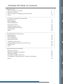
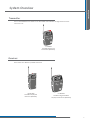
Dear Valued Customer,
Thank you for choosing Listen! All of us at Listen are dedicated to providing
you with the highest quality products available. We take great pride in their
outstanding performance because we care that you are completely
satisfied. That’s why we independently certify them to the highest quality
standards and back them with a limited lifetime guarantee. We stand ready
to answer any questions you might have during installation or in the operation
of our products. Should you experience any problems whatsoever with your
Listen products, we are ready to help you in any way we can with prompt,
efficient customer care. Because at Listen, it’s all about you! And should you
have any comments on how we might improve our products or our
service, we’re here to listen.
Here’s how to reach us:
+1.801.233.8992
+1.800.330.0891 North America
+1.801.233.8995 Fax
[email protected]
www.listentech.com
Listen Technologies GmbH
Jasminstr. 16
905 22 Oberasbach, Germany
+49 911 955159 0 Tel
+49 911 955159 40 Fax
www.listentech.de
[email protected]
Thank you and enjoy your listening experience!
Best regards,
Russell Gentner and the Listen Team
Lifetime Warranty – the best in the business!
Listen’s full-time technical support is passionate about what they do and you can depend
on them to solve any equipment issues with confidence. In the few instances where repairs
were needed, 99% of all clients indicated that they were happy with repair
turn-around-times and 85% of the time, clients were without their product for
less than 10 days!
Overall client satisfaction of working with Listen was rated 4.8 out of 5.
The Word Around Listen
“Please continue with your excellent attitude toward customer satisfaction. You guys
are great!”
“I’ve never had such good service from any company. Keep up the good work!”
“You stand behind your product wonderfully.”
Assistive Listening • Language Interpretation • Soundfield • Tour Group • Conferencing
LT-700-863 Portable FM Transmitter
Specifications
Block Diagram
Quick Reference
Setup Instructions
Operating Instructions
Programming Instructions
Accessories
Notes
17
18
19
20
23
25
28
29
LR-400/500-863 FM Receivers
Specifications
Block Diagram
Quick Reference
Setup Instructions
Operating Instructions
Programming Instructions (LR-500 only)
Accessories
Notes
37
39
40
42
45
51
52
53
Supplementary Information
Frequency Chart
Battery Charging Information
Troubleshooting
Frequently Asked Questions
Compliance, Warranty and Contact Information
Notes
61
62
63
65
67
68
LR-400/500
5
6
8
10
LT-700
Design Guide
FM Technology Overview
System Overview
Key Concepts in Designing an FM System
Notes
Design Guide
Portable FM Table of Contents
Supplementary
FM Technology Overview
System Overview
Key Concepts in Designing an FM System
Notes
Design Guide
Portable FM Design Guide Table of Contents
5
6
8
10
3
Design Guide
Frequency Modulation (FM) Technology Overview
Frequency modulation (FM) is a means of transmitting audio using electromagnetic waves.
This same technology is used by local FM radio stations to broadcast voice and music. FM signals can travel
through most barriers – walls, floors, and ceilings. The distance a signal travels has many different variables
such as Radio Frequency (RF) output power, the type and placement of the antenna and the broadcasted
frequency. This section of the manual will help you design a system that will get the best range with the least
amount of interference.
Microphone
FM Transmitter
Receiver
When designing an FM system it is important to keep the following in mind:
• Multipath
Multipath interference is a form of RF interference that occurs when radio signals have more than one path
between the receiver and the transmitter causing the two RF signals to add out of phase. This could occur in areas
with RF-reflective surfaces, such as furniture, walls, or floors. The result of multipath is the receiver audio coming in
and out of squelch when the receiver is moved. Portable applications are much more susceptible to multipath
than those that are stationary. Multipath distortion is often worse as the distance between transmitter and receiver
increases (RF power decreases). Multipath can decrease the audio quality of the transmission (refer to page 9 for
strategies on eliminating multipath).
• Antenna Positioning
For full RF functionality of the portable system, the antenna on both the LT-700 transmitter and receiver (LR-400/500)
must be in the upright position (shown below).
5
Design Guide
System Overview
There are three main parts to a Portable FM System – Input source, transmitter, and receiver.
LA-278
Behind-the-Head Microphone
(other microphones available)
LT-700-863
Portable Display FM
Transmitter (863 MHz)
LR-400-863
Portable Display FM
Receiver (863 MHz)
LR-500-863
Portable Programmable
Display FM Receiver (863 MHz)
Input Source
A microphone is the most common input source for the LT-700 transmitter, although, the LT-700 can transmit
two audio inputs at once on one transmission channel. With the use of the LA-263 both the inputs will be mixed.
Thus, a person can use a line input source and mic source.
3.5mm Phone Wiring
Unbalanced
+ Tip
+ Ring
Mic input
Line input
- Sleeve
6
-
Design Guide
System Overview
Transmitter
The LT-700 modulates the audio on an FM carrier and transmits the signal via an antenna on the unit.
LT-700-863
Portable Display FM
Transmitter (863 MHz)
Receivers
Listen offers two different portable receivers.
LR-400-863
Portable Display FM
Receiver (863 MHz)
LR-500-863
Portable Programmable
Display FM Receiver (863 MHz)
7
Design Guide
Key concepts in designing a portable FM system
Channel Selection
Use this section of the guide to choose the channel settings for the transmitter and receivers.
• The goal is to find a transmission channel(s) that is free from interference. Interference originates from
other transmitters and from other equipment (such as a computer).
• Listen products offer 17 different channels to choose from. This increases the chance you’ll find an
interference free channel.
• The best way to check for interference is to use the “SEEK” button on the receiver. Be sure all Listen
transmitters have been turned off if there is interference, the receiver will find these channels.
If the receiver finds a frequency in use, do not use this channel.
• In general, most of the channels will be free from interference.
• Interference can be overcome by maximizing the transmission power and by using the receivers close to
the transmitting antenna.
• If more than one channel is in use, space the channels further from each other. Use the Listen frequency
chart on page 61 to determine the appropriate channels.
EXAMPLE: 2 channel system use channels 01 & 11
3 channel system use channels 01, 06 & 11
Range
The range of a portable transmission will vary from one application to another. There are many different
obstructions that could minimize the range. In most applications, the range will be approximately as shown
below (P= Power Level - refer to page 26 for programming power levels of the LT-700).
P1 – 30 meters (100 ft)
P2 – 46 meters (150 ft)
P3 – 61 meters (200 ft)
Range varies depending on environment.
Maximizing Range
Here are some tips to maximize the transmission range:
• Eliminate or minimize obstructions between the transmitter and receivers.
• Minimize the distance between the transmitter and receivers.
• Move transmitter and receivers away from metal objects.
• Orient both transmitting and receiving antennas vertically.
8
Design Guide
Key concepts in designing a portable FM system
Eliminating Multipath
As mentioned on page 5, multipath can occur with portable RF systems. The audio quality of the
transmission can decrease with the occurrence of multipath. Here are a few potential improvements that
can help if multipath takes place:
Squelch
Squelching the receiver will mute the audio output when the signal from the transmitter is turned off or
the signal is too weak to be received. Without squelch you would hear radio noise in your earphone with
no RF signal present. “Tightening” the squelch will turn the receiver off if it is chattering because of
multipath (refer to page 48 for programming squelch). Keep in mind, “tightening” squelch will limit the
range between transmitter and Receiver.
Transmitter power level
The RF power level can be adjusted on the LT-700 (refer to page 26 for programming LT-700 power levels).
The lower the power setting, the less range the transmitter will broadcast. Decreasing the broadcast range
will force the receivers to remain closer to the transmitter. To maintain an RF signal, the higher power
settings will increase range between transmitter and receiver thus introducing a higher probability of
multipath.
Multiple Portable Systems
In some applications, there will be more than one RF transmission in the same general vicinity.
Intermodulation interference can occur if the transmission frequencies are too close together. Here are
some ways to eliminate the chance of RF interference:
Squelch
Much like a multipath situation, “tightening” the squelch on the receiver will mute the audio output when
the signal is too weak to be received. Tightening the squelch will help with force the receiver to squelch
when signal becomes too weak. (refer to page 48 for programming squelch).
Transmitter power level
As mentioned above, the RF power level can be adjusted on the LT-700 (refer to page 26 for programming
LT-700 power levels). The lower the power setting, the less range the transmitter will broadcast. Lowering the
power could help decrease the amount of interference if there are many frequencies being used in the
vicinity.
Spacing of channels
Use a Listen frequency chart (on page 61) to determine the channels frequency and space the number of
channels further from each other.
DX/Local
The receiver can be adjusted to receive only the strongest signals (refer to page 50 for DX/Local
information). A DX signal will be less sensitive because distance is the ultimate goal. For applications where
you want to minimize the distance, local mode will only search for strong signals. Local mode is much
more sensitive than DX.
9
Design Guide
Notes
10
Design Guide
Notes
11
LT-700 User’s Manual Table of Contents
Specifications
Block Diagram
Quick Reference
Setup Instructions
Operating Instructions
Programming Instructions
Accessories
Notes
17
18
19
20
23
25
28
29
LT-700
LT-800
LT-700 Package Contents
• LT-700-863
• Quick Reference Card
• Warranty Card
• FM Manual Card
LT-700-863
Portable Display FM
Transmitter (863 MHz)
Listen Configurations
• LT-700-863
15
LT-700-863 Specifications
Architectural Specification
The LT-700-863 portable FM Transmitter shall be capable of broadcasting on 17 channels. Channel tuning shall be capable of being
locked. The transmitter shall have a SNR of 70 db or greater. The output power shall be adjustable to quarter, half or full. The device
shall have an audio frequency response of 50 Hz to 15 kHz, +/-3 dB. The device shall incorporate a microphone sensitivity switch.
The device shall incorporate a mute switch. The unit shall utilize two 2 AA batteries. The battery door shall be capable of being
mechanically locked. The device shall incorporate an LCD display that indicates battery level, channel, channel lock, low battery,
battery charging, programming, and RF signal strength. The portable transmitter shall incorporate automatic battery charging
circuitry for recharging of NiMH batteries. The Listen LT-700-863 is specified.
RF
LT-700-863
863.050 - 864.950 MHz
17 wide band
± .005% stability 32 to 122º (0 to 50º C)
50 PPM
0 ft. (0 m) to 200 ft. (60.9 m)
10 mW maximum (adjustable)
Uses microphone cable
3.5 mm connector
CE, ETSI, RoHS
System Frequency
Response
System Signal to Noise
Ratio
System Distortion
50 Hz - 15 kHz (± 3 dB)
Microphone Input
Microphone Sensitivity
Line Input
Microphone Power
Controls
User Controls
Set-up Controls (battery
compartment)
Programming
Display
Physical
<2% total harmonic distortion (THD) at 80% deviation
Unbalanced, tip of 3.5mm connector, -20 dBu nominal, -30 dBu
maximum, impedance 21 ohms
Three position switch: high, middle, and low; 6 dB increments
Unbalanced, ring of 3.5mm connector, -10 dBu nominal input
level, -3 dBu maximum, impedance 10K ohms
3 VDC Bias
Power, mute, channel UP/DOWN
Mic sensitivity, NiMH/alkaline battery, SQ enable/disable
Channel Lock out, Channel lock
Battery Type
Battery Life
(Listen batteries)
Battery Charging
(NiMH only)
Two AA batteries, alkaline or NiMH
15 hours alkaline (LA-361), 8 hours NiMH rechargeable (LA362)
Fully automatic, 13 hours
Dimensions (H x W x D)
Color
Unit Weight
Unit Weight with batteries
Shipping Weight
3.00 x 1.00 x 5.00 in. (7.6 x 2.5 x 13.0 cm)
Dark Grey with white silk screening
3.9 oz (111 g)
5.8 oz (164 g)
1.0 lbs. (0.45 kg)
Manually Lockable. Up, down, and power buttons through
door. Other controls behind door (see controls)
Door
Environmental
70 dB (A-Weighted)
Red, illuminated when unit is on. Flashes when batteries are
low, or to indicate charging. Flashes when muted
Channel Designation, lock status, signal strength indication,
battery life, RF Power
LED
Indicators
Power
LT-700
LT-800
Audio
Specifications
RF Frequency Range
Number of Channels
Frequency Accuracy
Transmitter Stability
Transmission Range
Output Power
Antenna
Antenna Connector
Compliance
Temperature - Operation
Temperature - Storage
Humidity
14 to 104º F (-10 to 40º C)
-4 to 122° F (-20 to 50° C)
0 to 95% relative humidity, non-condensing
Specifications are subject to change without notification
17
LT-700 Block Diagram
Up
LCD Display
Down
Power Supply
CPU Module
115/230VAC
50/60 Hz
Universal
Power Supply
(not included)
Power
7.5 VDC
Power charge indicator
Red LED
Alkaline
NiMH
LT-700
LT-800
(2) AA Batteries
ALkaline or NiMH
ANTENNA
RF Modulation
Pre-emphasis
3 VDC
Tip
Mic
Sleeve
Line
Ring
18
Companding
Q-Technology
LT-700 Quick Reference
3.5mm Input Jack: Connect a Listen microphone here.
LED: When lit, indicates unit has power,
when flashing unit is muted/charging.
Mute On/Off switch
Articulating Flexible Antenna
Power/Charging Port
Power Button: Turns
power On/Off.
Front Door Lock
Battery Select Switch: Choose
the type of batteries being
used.
Channel Select Buttons
Channel Display: Displays the
channel the LT-700 is currently on.
RF Output
Indicator: Indicates
the RF transmit
level.
Program:
function is in
process.
Battery Compartment: Place
2-AA batteries in compartment.
Be sure to follow polarity
pattern.
Battery Level Indicator
L/O: Indicates while in
programming mode the specific
channel has been locked out.
Lock Icon: Indicates the unit is
locked on current channel.
19
LT-700
LT-800
Look&Listen™ Display: Shows
transmit level, channel,
programming, battery status, and
lock status.
LT-700 Setup Instructions
1
Unpack the Product
Remove outer packaging and plastic cover. Inspect for physical damage. If damage is apparent, please
contact the dealer from which the product was purchased or Listen Technologies
Corporation technical support for assistance (refer to page 67 for contact information).
2
Open the front access door
LT-700
LT-800
If locked, use a pocketknife or small screwdriver to unlock the door locks on both sides of the unit.
To unlock the door, rotate the lock ¼ turn counterclockwise. Grip the two tabs with your thumb and index
finger and pull the door downward. DO NOT place batteries in the unit at this time.
3
Select Battery Type
Two types of batteries may be used: NiMH or Alkaline. The unit is shipped with the switch in the Alkaline
position. Use a pen or small screwdriver to select the battery type.
WARNING: Do not place the BATTERY switch in the NiMH position if you are not using Nickel Metal Hydride
Batteries. The NiMH position will attempt to charge any batteries in the unit, even if they are
not the proper type. Charging non-Nickel Metal Hydride (NiMH) batteries will result in physical
harm, destruction of property and/or fire.
CAUTION: If you are using any battery type other than rechargeable Nickel Metal Hydride (NiMH)
batteries, make sure the BATTERY selection switch is in the alkaline position.
Battery select switch
20
LT-700 Setup Instructions
4
Set Mic Sensitivity Switch
The microphone sensitivity switch is located inside the battery compartment, to the left of the
BATTERY selection switch. The LT-700 is shipped with this switch in the center (MED) position. Listen
recommends the following settings for our microphones. If you are using a microphone from
another vendor, you may need to experiment with different settings.
Part #
LA-261
LA-262
LA-272
LA-274
LA-276
LA-277
LA-278
Description
Setting
Lavalier Microphone
Over-the-Head Microphone
Over-the-Head Microphone w/Earphone
Hand Held Microphone
Collar Microphone
Behind-the-Head Microphone
Conference Microphone
MED
MED
MED
HI
HI
MED
MED
LT-700
LT-800
NOTE: If the setting is too low for the microphone in use the audio will be faint. If the setting is too high
for the microphone in use the audio will be distorted.
5
Place Batteries in Unit
Place two AA batteries in the compartment, making note of the battery polarity shown in the
battery compartment, and again verifying that the BATTERY SELECT switch is in the correct position
for the batteries you are using. (Alkaline should be selected for all battery types other than NiMH).
+
-
-
+
--
+ +
21
LT-700 Setup Instructions
6
Connect the Microphone
LT-700
LT-800
The microphone jack is located on top of the unit.
7
Connect the Line Input Cable (Optional)
This cable allows you to connect a TV, CD player or other equipment to the LT-700. To do this, you must
order the Listen LA-263 Line Input Cable (not included with your unit). This cable allows you to connect
both a microphone and line input to the jack on top of the LT-700. See the diagram below for connection
information. You can use the microphone and the line input at the same time.
NOTE: The MUTE switch mutes only the microphone; the line source will continue transmitting when the
switch is in the MUTE position.
22
LT-700 Operating Instructions
1 Turn Unit On
1A P
Power On/Off Button
When you press the power button, the unit turns on. The LED on top of the unit will be
illuminated and the LCD display will be visible.
2 Antenna Positioning
e upright position. When the antenna if fu
Raise the antenna to the
fully upright, it will click
into position.
LT-700
LT-800
NOTE: Be aware that the transmission range could decrease if the antenna is
not in an upright position.
3 Select the channel for transmitting
863 MHz operates on 17
7 wide band channels. Channels are disp
displayed numerically (i.e. 01-17)
(refer to Channel Selection
guidelines on choosing an
tion in design guide page 8) for guideline
interference free channel.
nel
23
LT-700 Operating Instructions
7 Using the MUTE / TALK switch
LT-700
LT-800
Slide the switch to the mute position and the microphone audio is muted. When the
microphone audio is muted, the LED on top of the unit flashes rapidly. Slide the switch back to the talk
position and the microphone audio will return to the transmission. If you are using the line level input, it will
not be affected by the mute/talk switch.
Locking the Transmitter on One Channel
The unit can be electronically locked on one channel so that it will not change channels even if the channel select
buttons are pressed. It is recommended to lock the transmitter on a channel that is being used in a single channel system
or when multiple systems are in the same area.
1 To lock on a channel
1A Press and hold the DOWN button for 5 seconds
Press and hold the DOWN button for 5 seconds to lock the transmitter onto the desired
channel. Press and hold the button again to unlock.
NOTE: On the LT-700, when the channel is locked, a lock icon will appear underneath
“Listen” on the display.
24
LT-700 Programming Instructions
Program Mode Overview
The LT-700 can be programmed to transmit on a limited number of channels. For applications where users are
required to select a channel (such as classrooms or language interpretation application), and you don’t want
them to have to scroll through all of the available channels, this feature is ideal. The LT-700 can also be changed
from high to low power levels. Adjusting the power settings allows you to set the range of the transmission.
Entering Program Mode
While the unit is ON, press and hold the channel down and up buttons simultaneously for 3 seconds.
2
The “PGM” icon on the LCD will appear indicating program mode is entered.
LT-700
LT-800
1
25
LT-700 Programming Instructions
3
Once in the program mode, a function menu is displayed. Function 1 (F1) is displayed as default. Pressing the
channel up or down buttons will scroll through the functions. Pressing the power button will enter that function.
LT-700
LT-800
F1- Channel Lock out. No channels are locked out as default. Pressing the up and down buttons will scroll through
channels. Pressing the power button will toggle between lock/lockout for that channel. When a channel is
locked out, the L/O on the LCD shall be displayed.
F2- Transmitter Power. High transmit power (P3) is the default. Pressing the channel up button will toggle
through the following settings:
a. Low power: LCD displays “P1”
b. Med power: LCD displays “P2”
c. High power: LCD displays “P3”
4
26
When no button is pressed for 10 seconds, the program menu is exited altogether, regardless of whether a
function is entered or not. To exit out of the program menu or function manually:
4A
When in the programming menu: Press and hold power for 2 seconds. This exits the program mode.
W
4B
When in a programming function: Press and hold power for 2 seconds. This exits the function and goes back to
W
tthe programming menu.
4C
Pressing and holding power for a full 4 seconds will exit both programming function and programming menu.
P
LT-700 Programming Instructions
Resetting to defaults
To reset the transmitter to default settings, follow these instructions:
3 Reset to default settings
and hold the Up and Down channel buttons while turning the unit on.
P
4A Press
Press and hold the Up and Down channel buttons while turning the unit on. This will light
up all segments of the display.
4B A
After the transmitter has been reset
After the transmitter has been reset, the display will return with defaults present.
NOTE: The defaults are
• Power Level: P3
• Channel: 01
* Channel lockout: All channels active
LT-700
LT-800
27
Accessories for LT-700
Accessories
LA-261
LA-272
Over-the-Head Microphone
w/Earphone
LT-700
LT-800
Lavalier Microphone
LA-262
Over-the-Head Microphone
ne
LA-274
Hand Held Microphone
LA-278
Behind-the-Head
Microphone
LA-311
LA-313
LA-317
LA-318
LA-320
LA-321
LA-322
LA-323
LA-324
LA-325
28
LA-276
Collar Microphone
LA-304
Assistive Listening
Notification Signage Kit
16-Unit Portable Charging/Carrying Case
16-Unit Portable Carrying Case
4-Unit Portable Charging/Carrying Case
4-Unit Portable Carrying Case
Configurable Carrying Case
8-Unit Portable Charging/Carrying Case
8-Unit Portable Carrying Case
4-Unit Portable Charging/Carrying Case w/Removable Lid
8-Unit Portable Charging/Carrying Case w/Removable Lid
16-Unit Portable Charging/Carrying Case w/Removable Lid
LA-277
Conference Microphone
LA-361
High Capacity AA Alkaline
Batteries (2)
LA-362
Rechargeable AA NiMH
Batteries (2)
Notes
LT-700
LT-800
29
LT-700
LT-800
Notes
30
LR-400/500 User’s Manual Table of Contents
Specifications
Block Diagram
Quick Reference
Setup Instructions
Operating Instructions
Programming Instructions (LR-500 only)
Accessories
Notes
37
39
40
42
45
51
52
53
LR-400/500 Package Contents
• LR-400/500
• Quick Reference Card
• Warranty Card
LR-400/500
LR-400-863
Portable Display
FM Receiver
(863 MHz)
LR-500-863
Portable Programmable
Display FM Receiver
(863 MHz)
Listen Configurations
• LR-400-863
• LR-500-863
35
LR-400-863 Specifications
Architectural Specification
The LR-400-863 FM receiver shall be capable of receiving on 17 wide band channels with a SNR of
70 dB or greater. The device shall be able to be locked on a single channel. The receiver shall be
capble of seeking channels. The device shall have an adjustable squelch. The device shall have an
audio frequency response of 50 Hz to 15 KHz, ±3 dB. The device will incorporate a stereo headset jack
that allows the user to plug in either a mono or stereo headset. The device shall incorporate an LCD
display that indicates channel, battery level, low battery, battery charging, and RF signal strength.
The receiver shall be able to function in both DX and Local mode. The unit shall operate off of 2 AA
batteries. The receiver shall incorporate automatic battery charging circuitry for recharging of NiMH
batteries. The Listen LR-400-863 is specified.
RF
Audio
Specifications
RF Frequency Range
Number of Channels
Sensitivity
Frequency Accuracy
Antenna
Squelch
Compliance
LR-400-863
863.050 - 864.950 MHz
17 Wideband
.6uV typical, 1 uV maximum for 12 dB sinad
± .005% stability 32 to 122º (0 to 50º C)
Integrated External Antenna
Programmable in 20 steps, automatic on loss of RF signal
CE, ETSI, RoHS
System Frequency Response
System Signal to Noise Ratio
System Distortion
50 Hz - 15 kHz (+/-3 dB)
70 dB (A-Weighted)
<2% total harmonic distortion (THD) at 80% deviation
3.5 mm connector, unbalanced, 0dBu nominal output level, 16
mW maximum, impedance 32 Ohms
Output
Controls
User Controls
Set-up Controls (battery compartment)
Programming
Red, illuminated when unit is on. Flashes when batteries are
low, or Charging. Flashes when locked and SEEK is pushed.
Channel Designation, lock status, signal strength indication,
battery life
LED
Indicators
LCD Display
Battery Life (Listen batteries)
Battery Charging (NiMH only)
Physical
Dimensions (H x W x D)
Color
Unit Weight
Unit Weight with batteries
Shipping Weight
Door
Temperature - Operation
Environmental Temperature - Storage
Humidity
LR-400/500
Battery Type
Power
Channel up/down, SEEK, volume
Alkaline/NiMH battery switch
Channel Lock, DX/Local, squelch
Type: 2 AA batteries, alkaline or NiMH
20 hours alkaline (LA-361), 10 hours NiMH rechargeable
(LA-362)
Fully Automatic, 13 hours maximum
5.0 x 3.0 x 1.0 in (13 x 7.6 x 2.5 cm)
Dark Grey with white silk screening
3.9 oz (111 g)
5.8 oz (164 g)
1.0 lbs. (0.45 kg)
Manually Lockable. Up, down, and power buttons through
door. Other controls behind door (see controls)
-10 C (14 F) to +40 C (104 F)
-20 C (-4 F) to +50 C (122 F)
0 to 95% Relative Humidity, non condensing
Specifications are subject to change without notification
37
LR-500-863 Specifications
Architectural Specification
The LR-500-863 FM receiver shall be capable of receiving on 17 wide band channels with a SNR of
70 dB or greater. The receiver shall be programmable to electronically lock out unneeded channels.
The receiver shall be capable of seeking channels. The device shall be able to be locked on a single
channel. The device shall have an adjustable squelch. The device shall have an audio frequency
response of 50 Hz to 15 KHz, ±3 dB. The device will incorporate a stereo headset jack that allows the
user to plug in either a mono or stereo headset. The device shall incorporate an LCD display that
indicates channel, battery level, low battery, battery charging, and RF signal strength. The receiver
shall be able to function in both DX and Local mode. The unit shall operate off of 2 AA batteries. The
receiver shall incorporate automatic battery charging circuitry for recharging of NiMH batteries. The
Listen LR-500-863 is specified.
RF
Specifications
RF Frequency Range
Number of Channels
Sensitivity
Frequency Accuracy
Antenna
LR-500-863
863.050 - 864.950 MHz
17 Wideband
.6uV typical, 1 uV maximum for 12 dB sinad
± .005% stability 32 to 122º (0 to 50º C)
Integrated External Antenna
Programmable in 20 steps, automatic on loss of RF signal
Squelch
Audio
Compliance
CE, ETSI, RoHS
System Frequency
Response
System Signal to Noise
Ratio
System Distortion
50 Hz - 15 kHz (+/-3 dB)
Output
Controls
User Controls
Set-up Controls (battery
compartment)
Programming
LR-400/500
LT-800
Indicators
LCD Display
Physical
Channel up/down, SEEK, volume
Alkaline/NiMH battery switch
Channel Lock Out, Channel Lock, DX/Local, squelch
Battery Type
Battery Life (Listen
batteries)
Battery Charging (NiMH
only)
Type: 2 AA batteries, alkaline or NiMH
20 hours alkaline (LA-361), 10 hours NiMH rechargeable (LA-362)
Dimensions (H x W x D)
Color
Unit Weight
Unit Weight with batteries
Shipping Weight
5.0 x 3.0 x 1.0 in (13 x 7.6 x 2.5 cm)
Dark Grey with white silk screening
3.9 oz (111 g)
5.8 oz (164 g)
1.0 lbs. (0.45 kg)
Manually Lockable. Up, down, and power buttons through door.
Other controls behind door (see controls)
Door
Environmental
<2% total harmonic distortion (THD) at 80% deviation
3.5 mm connector, unbalanced, 0dBu nominal output level, 16 mW
maximum, impedance 32 Ohms
Red, illuminated when unit is on. Flashes when batteries are low, or
Charging. Flashes when locked and SEEK is pushed.
Channel Designation, lock status, signal strength indication, programming
LED
Power
70 dB (A-Weighted)
Temperature - Operation
Temperature - Storage
Humidity
Fully Automatic, 13 hours maximum
-10 C (14 F) to +40 C (104 F)
-20 C (-4 F) to +50 C (122 F)
0 to 95% Relative Humidity, non condensing
Specifications are subject to change without notification
38
LR-400/500 Block Diagram
Up
LCD Display
Down
Power Supply
CPU Module
115/230VAC
50/60 Hz
Seek
Universal
Power Supply
(not included)
Alkaline
Power charge indicator
Red LED
NiMH
(2) AA Batteries
ALkaline or NiMH
POWER
On
Off
ANTENNA
RF
de-modulation
de-emphasis
Companding
Q-Technology
VOLUME
Tip
3.5 mm Connector
Sleeve
Ring
LR-400/500
39
LR-400-863 Quick Reference
Articulating Flexible Antenna
3.5 mm Output Jack: Connect a listen earpiece here.
LED: When lit, indicates unit has power.
On/Off and Volume Control Dial
Look&Listen™ Display: Shows
receive level, channel, battery
status, and lock status.
Power/Charging Port
SEEK Button: Allows the
user to change channels
or lock on a channel.
Front Door Lock
Battery Select Switch: Choose
the type of batteries being
used.
Battery Compartment: Place
2-AA batteries in compartment.
Be sure to follow polarity
pattern.
LR-400/500
LT-800
Channel Select Buttons
Channel Display: Displays the
channel the LR-400 is currently on.
RF Input Indicator:
Indicates the RF receive
level.
Battery Level Indicator
Lock Icon: Indicates the unit is
locked on current channel.
40
LR-500-863 Quick Reference
3.5 mm Output Jack: Connect a listen earpiece here.
LED: When lit, indicates unit has power.
On/Off and Volume Control Dial
Articulating Flexible Antenna
a
Look&Listen™ Display:
Shows receive level, channel,
programming, battery
status, and lock status.
Power/Charging Port
SEEK Button: Allows the
user to change channels
or lock on a channel.
Front Door Lock
Battery Select Switch: Choose
the type of batteries being
used.
Channel Select Buttons
Battery Compartment: Place
2-AA batteries in compartment.
Be sure to follow polarity
pattern.
LR-400/500
Channel Display: Displays the
channel the LR-500 is currently on.
RF Input
Indicator:
Indicates the
RF receive
level.
Program:
Function is
in process.
Battery Level Indicator
L/O: Indicates while in programming
mode the specific channel has
been locked out.
Lock Icon: Indicates the unit is
locked on current channel
41
LR-400/500 Setup Instructions
1
Remove the product
Remove outer packaging and plastic cover. Inspect for physical damage. If damage is apparent,
please contact the dealer from which the product was purchased or Listen Technologies Corporation technical support for assistance (refer to page 67 for contact information).
2
Open the front access door
If locked, use a pocketknife or small screwdriver to unlock the door locks on both sides of
the unit. To unlock the door, rotate the lock ¼ turn counterclockwise. Grip the two tabs with
your thumb and index finger and pull the door downward. DO NOT place batteries in the
unit at this time.
3
Select Battery Type
LR-400/500
LT-800
Two types of batteries may be used: The unit is shipped with the switch in the Alkaline position.
Use a pen or small screwdriver to select the battery type.
Battery select switch
WARNING: Do not place the BATTERY switch in the NiMH position if you are not using
Nickel Metal Hydride Batteries. The NiMH position will attempt to charge
any batteries in the unit, even if they are not the proper type. Charging
non-Nickel Metal Hydride (NiMH) batteries will result in physical harm,
destruction of property and/or fire.
CAUTION: If you are using any battery type other than rechargeable Nickel Metal
Hydride (NiMH) batteries, make sure the BATTERY selection switch is in the
alkaline position.
42
LR-400/500 Setup Instructions
4
Place Batteries in Unit
Place two AA batteries in the compartment, making note of the battery polarity shown in the battery
compartment, and again verifying that the BATTERY SELECT switch is in the correct position for the
batteries you are using. (Alkaline should be selected for all battery types other than NiMH).
NOTE: Listen provides industrial strength AA alkaline batteries (part number LA-361) and high
performance AA Nickel Metal Hydride batteries (part number LA-362). These may be
purchased from your Listen dealer.
+
-
-
+
--
+ +
5
Connect an Earphone or Headset
Your headset or earphone will connect to the jack on the top of the unit. Either mono or stereo
connectors may be used with a Listen receiver. Make certain you push the plug all the way into
the jack.
LR-400/500
43
LR-400/500 Setup Instructions
6
Turn the Unit On
LR-400/500
LT-800
Receivers are turned on by rotating the volume dial counterclockwise. The red LED on top of the unit will
illuminate and the LCD display should illuminate. If they do not, make sure you have installed the batteries correctly and that you are using fully charged batteries.
44
LR-400/500 Operating Instructions
1
Turn Unit On
1A Volume knob
Rotate the volume knob counterclockwise with an earphone or headset connected to
the unit.
WARNING: Excessive volume may result in hearing damage.
2
Antenna Placement
2A Antenna Position
Raise the antenna to the upright position. When the antenna if fully extended, it will
click into position.
NOTE: Be aware that the transmission range could decrease if the antenna is
not in an upright position.
LR-400/500
3
Select a Channel
3A Select the channel using channel select buttons
Select the channel to match the transmission channel by pressing the UP and DOWN
buttons on the receiver.
45
LR-400/500 Operating Instructions
3A Select the channel using SEEK
Another way to find a channel on the LR-400/500 is to use the SEEK button.
When you do this, the Listen receiver looks for the next active channel.
Sometimes the unit will mistake interference for a real broadcast signal. If you
get interference, press the SEEK button again. The unit may stop on a
channel that is close to the actual broadcast channel, in which case the
channel will sound noisy or distorted. Simply press SEEK again until you find the
clearest operating channel.
4
Adjust the volume control
LR-400/500
LT-800
Use the control dial on the top of the unit to adjust the volume to a comfortable level.
46
LR-400/500 Operating Instructions
Locking the Receiver on One Channel
The unit can be electronically locked on one channel so that it will not change channels even if the “SEEK” button is
pressed. It is recommended to lock the receiver on a channel that is being used in a single channel system or when multiple systems are in the same area.
1 To lock on a channel
1A Press and hold the SEEK button for 5 seconds
Press and hold the SEEK button for 5 seconds to lock a receiver onto the currently tuned
channel. Press and hold the button again to unlock. When locked the LED on top of
the unit will flash when you press the SEEK button.
NOTE: On the LR-400/500, when the channel is locked, a lock icon will appear underneath
“Listen” on the display. Also if the unit is locked, the red LED on top of the receiver will
flash when the SEEK button is pressed.
LR-400/500
47
LR-400/500 Operating Instructions
Squelch Programming
Entering Squelch Program Mode
1
Turn unit off
2
Press and hold the SEEK button; while holding SEEK button down, turn the ON/OFF/VOLUME dial to turn
the unit on.
3
Release the SEEK button when the Listen name disappears (approximately 2 seconds) and a two digit
display is seen.
Adjusting the Squelch level
1
Use the Channel UP and DOWN buttons to raise or lower the squelch sensitivity settings (refer to the chart on
page 49 for settings.
2
Lower numbers mean that a less powerful and possibly noisy signal will be heard, but you can have a
longer range before the unit will squelch.
3
Once the desired squelch setting is found, press SEEK to exit the squelch programming mode.
NOTE: Keep in mind, low squelch may allow multipath and squelch chattering at long distances.
Squelch setting 00 is no squelch; this setting disables the squelching capabilities of the receiver. Squelch
setting 20 is maximum squelch sensitivity; when on this setting, there must be a very strong and stable
RF signal for the unit to not engage the squelch feature.
LR-400/500
LT-800
NOTE: For squelch settings 1-3, the squelch function is slow which allows for maximum
transmission range. For squelch settings 4-20 the squelch function is fast to ensure little
radio noise is heard during the squelch function.
48
LR-400/500 Operating Instructions
Squelch
The purpose of squelch is to mute the audio output of your receiver when the signal from the
transmitter is turned off or is too weak to be received. Without squelch you would hear radio noise
in your earphone. The squelch on your receiver can be adjusted so that it will mute the audio on
different RF signal strengths. This is useful as follows:
Squelch
Setting
Squelch
Set the squelch setting to the highest level
0
1
No Squelch
To ensure that users don’t hear transmissions from other
transmitters, set the squelch setting to the highest level that
doesn’t squelch the receiver.
2
If the receiver is close to the transmitter, set the squelch high
3
(default)
4
5
6
If in an area that has a lot of interference, set the squelch high
If you are in an area that has a lot of inference, you may want to
set the squelch setting to a high setting to ensure the
interference is not picked up by the receiver.
Loose Squelch
(Most Range)
If the receiver is going to be close to the transmitter (i.e. in
a classroom), set the squelch setting high so that when the
transmitter is turned off it immediately squelches and ignores
transmitters in other rooms.
7
8
9
10
For maximum amount of range, set the squelch to a low level
11
LR-400/500
If you need the maximum amount of range, you may want to
consider setting the squelch setting to a low level (0, 1 or 2).
12
NOTE: Default squelch setting is 3
13
CAUTION: When setting the squelch level low the reliability of squelch
function is compromised. This will cause radio noise to be heard
in the earphone and there is a possibility of hearing damage.
14
15
16
17
19
20
Tight Squelch
(Least Range)
18
49
LR-400/500 Operating Instructions
DX/Local
DX is the normal operational mode. Local mode can effectively limit any inter-modulation and/or
interference in a busy RF environment. This is done by limiting the amount of RF gain in the receiver.
When local mode is selected, the range of the receiver is compromised. Depending on your application
and environment, Local mode may be necessary for better performance. DX mode is default.
DX Mode (default)
DX is normal operation. The local mode feature can be used
when many frequencies are being used.
Local mode
Only strong channels will be automatically tuned in
1 To change to DX/Local mode
1A
While the unit is OFF, press and hold the channel down button and turn the unit on.
1B
The LCD shall indicate the current setting “D” or “L”.
1C
Pressing the down button will toggle between Local and DX Mode; “D” or “L”.
1D
Pressing seek will enter the setting and return to normal operational mode.
LR-400/500
LT-800
DX
Local
Resetting to defaults
To reset the receiver to default settings, follow these instructions:
1 Reset to default settings
1A Press and hold the Up and Down channel buttons while turning the unit on.
Press and hold the Up and Down channel buttons while turning the unit on. This will light
up all segments of the display.
1B After the receiver has been reset
After the receiver has been reset, the display will return with defaults present.
NOTE: The defaults are
• Channel: 01
* Channel lockout: All channels active
50
LR-500 Programming Instructions (LR-500 only)
Programming Instructions
The LR-500 can be programmed to receive on a limited number of channels. When an
application requires the use of more than one channel (i.e. a classroom or language
interpretation), the receiver can be programmed to view only the necessary channels.
Entering Program Mode
1 To enter program mode
1A
While the unit is ON, press and hold the channel down and up buttons simultaneously for 3 seconds.
1B
The “PGM” icon on the LCD will appear indicating program mode is active.
2 To program
2A
LR-400/500
Once in the program mode, a function menu is displayed. Function 1 (F1) is displayed as default.
Pressing the channel up or down buttons will scroll through the functions (F1).
Pressing the seek button will enter that particular function.
F1- Channel Lock out. No channels are locked out as default. Pressing the up and down buttons will scroll through
channels. Pressing the seek button will toggle between available and locked out for that channel. When a channel is locked out, the L/O on the LCD shall be displayed.
NOTE: Although it is possible to display an F2 function while in program mode, there is no F2 function at this
time. Listen may add another programming function in the future, but there is only one programming
function (F1) on the 863 MHz receivers.
3
When no button is pressed for 10 seconds, the program menu is exited altogether, regardless of whether a
function is entered or not. To exit out of the program menu or function manually:
3A
When in the programming menu: Press and hold power for 2 seconds. This exits the program mode.
3B
When in a programming function: Press and hold power for 2 seconds. This exits the function and goes back to
the programming menu.
3C
Pressing and holding power for a full 4 seconds will exit both programming function and programming menu.
51
Accessories for LR-400/500
Accessories
LA-164
Ear Speaker
Stereo Headphones
LA-304
Assistive Listening
Notification Signage Kit
LR-400/500
LT-800
LA-170
LA
170
LA-170
Behind-the-Head
Stereo Headphones
LA-165
LA-166
Neck Loop
LA-361
High Capacity AA Alkaline
Batteries (2)
LA-362
Rechargeable AA NiMH
Batteries (2)
LA-311
LA-313
LA-317
LA-318
LA-320
LA-321
LA-322
LA-323
LA-324
LA-325
52
16-Unit Portable Charging/Carrying Case
16-Unit Portable Carrying Case
4-Unit Portable Charging/Carrying Case
4-Unit Portable Carrying Case
Configurable Carrying Case
8-Unit Portable Charging/Carrying Case
8-Unit Portable Carrying Case
4-Unit Portable Charging/Carrying Case w/Removable Lid
8-Unit Portable Charging/Carrying Case w/Removable Lid
16-Unit Portable Charging/Carrying Case w/Removable Lid
Notes
LR-400/500
53
LR-400/500
LT-800
Notes
54
LR-400/500
57
Supplementary Information Table of Contents
Frequency Chart
Battery Charging Information
Troubleshooting
Frequently Asked Questions
Compliance, Warranty and Contact Information
Notes
61
62
63
65
67
68
Supplementary
59
Frequency Chart
Frequencies
Supplementary
61
Battery Charging Information
The LT-700 and LR-400/500 receivers are unique because they have SmartCharge™ chargers built in. When any of these units are placed
into a Listen charging case, NiMH batteries will be charged.
SmartCharge™ uses a pulse charging, which greatly extends the life of Nickel Metal Hydride (NiMH) batteries. The entire charging process
takes about 13 hours. Listen recommends that you allow the charger to complete its full cycle every time for maximum battery life.
During the charge cycle, the red LED on top of the Listen product will flash slowly. When charging is completed, the LED will turn off. It is not
necessary to unplug the charger; however, if you unplug the unit from the charger and then plug it back in, it will begin the 13-hour charge
cycle over again.
When not using the receiver, it is recommended to leave the unit on the charger. The charger provides a “maintenance”
charge that keeps the battery at 100%. If the unit is not on the charger, the battery will lose up to 20% of its charge per month.
NOTE: Listen provides 2300 mAH (milli-Amp-hour) constant current (NiMH Nickel Metal Hydride) batteries.
These may be purchased from Listen (part number LA-362).
Charging with a drop-in charger
To charge the batteries using a drop-in charger, simply place the unit into a slot in the charger and connect
the charger to power. Make sure the unit is fully seated in its slot.
IMPORTANT: DO NOT ATTEMPT TO CHARGE ANY TYPE OF BATTERY OTHER THAN NiMH (NICKEL METAL HYDRIDE) with
your Listen equipment. Alkaline batteries may explode when connected to a charger. Other risks of
charging non-NiMH batteries include destruction of property or fire.
IMPORTANT: In order to charge NiMH batteries, the BATTERY SELECT switch in your Listen product must be set to the
NiMH setting. Use a pen or small screwdriver to move the switch (located in the battery compartment)
to the proper position.
Supplementary
LT-800
WARNING: The case lid MUST be open or removed while the units are charging. The charging process generates
heat. Air ventilation is required. It is best to store your charging case at room temperature away from
heat sources and direct sunlight.
62
Troubleshooting
Troubleshooting
The unit has no power.
Make sure the unit has fully charged batteries. Press the POWER button. If this does not work, try a
different set of batteries. Make sure the batteries are installed correctly.
There is no audio.
Make sure the MUTE/TALK switch is in the TALK position. Make sure you have the microphone plugged
all the way into the input jack. Make sure you are using a Listen approved microphone (see list on
page 21). If you are using the line input, make sure you have connected a line level, unbalanced input
at the “ring” of the connector. Also,be sure the receiver is on, volume is turned “up”, and headphones
are placed firmly in the jack .
The audio is distorted.
Make sure you are using an approved Listen microphone. Try using a different mic sensitivity switch
setting (the switch is located inside the battery compartment of the unit). If you are using a line level
input, try turning down the level of the input. Make sure the receiver is “ON” and receiving the
appropriate channel.
There is hum in the audio.
The microphone may be too close to a transformer. Try moving away from the transformer and see if
the hum goes away.
The microphone level is low.
The mic sensitivity switch may be on the wrong setting, (see page 21). Try a different setting (the switch
is located inside the battery compartment). Some microphones have directional pickups, ensure that
the microphone in use is oriented and positioned properly (pointing at the speakers mouth).
The microphone must be in close proximity to the person who is speaking. If this does not work, try using
a head-worn microphone.
There is too much noise.
This is most likely because the microphone is not close enough to the talker’s mouth, and it is picking up
background noise. Try positioning the microphone closer or try using a microphone that is directional
(such as a head-worn mic). Try another setting on the mic sensitivity switch (located inside the battery
compartment).
There is interference.
Try different frequencies to find a clear channel. Use a receiver to sweep the area without any
transmitters “on”. The receiver will stop on any channels that are being broadcasted in the area.
Avoid the channels that the receiver detects having a signal.
I cannot pick up the signal on the receiver.
Make sure the transmitter and the receiver are on the same frequency channel.
It’s confusing for users to have 17 available channels.
Use the PROGRAM function (LT-700 and LR-500 only) to lock out unwanted channels. Users will only be
able to scroll through available channels.
Supplementary
I cannot change the channel.
The transmitter or receiver may be locked on a channel (check for the padlock icon). To unlock, press
and hold the UP or DOWN button for 5 seconds.
63
Troubleshooting
Troubleshooting
My batteries are not charging
Make sure you are using NiMH batteries and that the BATTERY SELECT switch (inside the battery
compartment) is set to the NiMH position. Make sure the batteries are installed correctly. Make sure
you are using a Listen charging case. Make sure the charging case is connected to power and
the unit is securely pushed into its slot in the case.
Supplementary
LT-800
NOTE: Listen uses 2300 mAh (milli-Amp-hour) constant current NiMH (Nickel Metal Hydride) batteries. These
may be purchased from a Listen dealer (ask for part number LA-362).
64
Frequently Asked Questions
Frequently Asked Questions
a transmitter for each audio source?
Q Do I need
Yes. To transmit two different frequencies, there must be two separate transmitters.
A
is the range of the LT-700 Transmitter?
Q What The
range of the LT-700 will depend upon the power setting and interference (refer to page 8).
A Generally the range is up to 61 m (200 ft.).
to the number of transmitters I can use in one room?
Q Is thereYes.a limit
Listen recommends that no more that 8 channels are in used simultaneously (refer to page 9 on
A using multiple channels in the same room).
should be used with multiple trasmitters?
Q What reciever
We recommend the LR-500 for use with multiple transmitters, because the LR-500 is programmable
A
and can lock out unused channels.
channels can I program into the LR-500?
Q How many
1 to 17. The receiver has 17 channels and you can program it to have just the channels you want
A to have access to. It can be a two channel receiver, a 12 channel receiver, or keep all 17.
receivers can I have in a system?
Q How many
As many as you need, the number is endless.
A
are the major differences between the LR-400 and the LR-500?
Q What Both
receivers can tune to 17 broadband channels. However, the LR-400 has the buttons under
A the battery compartment door and the LR-400 is not programmable to lock out channels. If you
plan to use one receiver with multiple transmitters you should use the LR-500 which is
programmable to just those channels you need.
is the battery life of the LT-700 Transmitter?
Q What Fifteen
hours alkaline. Eight hours NiMH.
A
Supplementary
65
Frequently Asked Questions
Frequently Asked Questions
receiver be “locked” on a channel if needed?
Q Can the
Yes. All Listen receivers can be locked on a single channel.
A
battery life of a receiver?
Q What20is the
hours using alkaline batteries. 10 hours using NiMH batteries.
Supplementary
LT-800
A
66
Compliance, Warranty and Contact Information
Compliance Information
The following compliance information applies to the LT-800-863, LT-700-863, LR-500-863 and LR-400-863
These devices comply with ETSI EN 301 357
These devices are CE compliant.
These devices are RoHS compliant.
Warranty
Listen Technologies Corporation (Listen) warrants its transmitters and receivers (models LT-700, LT-800, LR-42, LR-44,
LR-100, LR-300, LR-400, LR-500 and LR-600) to be free from defects in workmanship and material under normal use
and conditions for the useful lifetime of the product from date of purchase.
Listen warrants it’s Stationary IR Radiators (LA-140) to be free from defects in workmanship and material under normal use and conditions for three years from the date of purchase.
Listen warrants its Noise Canceling Microphone (LA-270) to be free from defects in workmanship and material under
normal use and conditions for one year from date of purchase.
All other products and accessories are warranted for 90 days from date of purchase.
This warranty is only available to the original end purchaser of the product and cannot be transferred. Warranty is
only valid if warranty card has been returned, or online warranty registration, has been completed within 90 days
of purchase. This warranty is void if damage occurred because of misuse or if the product has been repaired or
modified by anyone other than a factory authorized service technician. Warranty does not cover normal wear and
tear on the product or any other physical damage unless the damage was the result of a manufacturing defect.
Warranty does not include inbound freight costs. Listen is not liable for consequential damages due to any failure
of equipment to perform as intended. Listen shall bear no responsibility or obligation with respect to the manner of
use of any equipment sold by it. Listen specifically disclaims and negates any warranty of merchantability or fitness
of use of such equipment including, without limitation, any warranty that the use of such equipment for any purpose
will comply with applicable laws and regulations. The terms of the warranty are governed by the laws of the state of
Utah.
In the first ninety days after purchase, any defective product will be replaced with a new unit. After 90 days, Listen
will, at its own discretion either repair or replace transmitters and receivers with a new unit or a unit of similar type
and condition. Product that is not covered under warranty shall be repaired or replaced with a unit of similar type
and condition based on a flat fee.
This limited warranty, prices and the specifications of products are subject to change without notice.
Contacting Listen
14912 Heritagecrest way
Salt Lake City, Utah U.S.A. 84065-4818
+1.801.233.8992
+1.800.330.0891 North America
+1.801.233.8995 Fax
[email protected]
www.listentech.com
Supplementary
If technical service is needed, please contact Listen. Pre-authorization is required before returning Listen products. If products were
damaged in shipment, please contact the carrier, then contact Listen for replacement or repair requirements payable by the
carrier.
All Listen European markets are supported through the Listen Technologies GmbH office located in Oberasbach, Germany. For
more information on Listen solutions, contact Listen Technologies at +1.801.233.8992, +1.800.330.0891 North America,
Listen Technologies GmbH at +49 911 955159-0 or visit www.listentech.com. For Europe, Middle East, Africa and India office visit
www.listentech.de.
Listen Technologies GmbH
Jasminstr.16, 90522 Oberasbach, Germany
+49 911 955 159 0 Europe
+49 911 955 159 40 Fax
[email protected]
www.listentech.de
67
Supplementary
LT-800
Notes
68
Listen Technologies Corporation
14912 Heritagecrest Way
Bluffdale, Utah 84065-4818, U.S.A.
+1.801.233.8992
1.800.330.0891 North America
+1.801.233.8995 Fax
www.listentech.com
[email protected]
Printed in the United States of America
© 2011 Listen Technologies Corporation® All Rights Reserved 201109.28