1
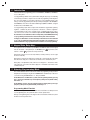
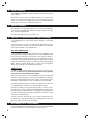
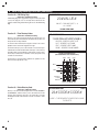
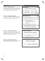
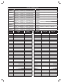
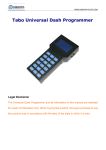
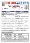
PRINTER’S INSTRUCTIONS:
INSTR,ACCESS LOCAL PROGRAMMING - LINEAR P/N: 228505 A - INK: BLACK - MATERIAL: 20 LB. MEAD BOND - SIZE: 8.500” X 11.000” - SCALE: 1-1 - FOLDING: ALBUM-FOLD - BINDING: SADDLE-STITCH
AE1000Plus
AE2000Plus
AM3Plus
Local Programming
Addendum
USA & Canada (800) 421-1587 & (800) 392-0123
(760) 438-7000 - Toll Free FAX (800) 468-1340
www.linearcorp.com
Table of Contents
1 Introduction . . . . . . . . . . . . . . . . . . . . . . . . . . . . . . . . . . . . . . . . . . . . . . . . . . . . . . . . . . . . . . . . . . . . . . . . . . . . . . . . . . . . 1
Important Local Programming Note for Network Installations . . . . . . . . . . . . . . . . . . . . . . . . . . . . . . . . . . . . . . . . . . . . . 1
2 Keypad Data Entry Keys . . . . . . . . . . . . . . . . . . . . . . . . . . . . . . . . . . . . . . . . . . . . . . . . . . . . . . . . . . . . . . . . . . . . . . . . . . 1
3 Entering Programming Mode . . . . . . . . . . . . . . . . . . . . . . . . . . . . . . . . . . . . . . . . . . . . . . . . . . . . . . . . . . . . . . . . . . . . . . 1
Programming Mode Time Out . . . . . . . . . . . . . . . . . . . . . . . . . . . . . . . . . . . . . . . . . . . . . . . . . . . . . . . . . . . . . . . . . . . . . 1
4 Visual Feedback . . . . . . . . . . . . . . . . . . . . . . . . . . . . . . . . . . . . . . . . . . . . . . . . . . . . . . . . . . . . . . . . . . . . . . . . . . . . . . . . . 2
5 Audible Feedback . . . . . . . . . . . . . . . . . . . . . . . . . . . . . . . . . . . . . . . . . . . . . . . . . . . . . . . . . . . . . . . . . . . . . . . . . . . . . . . . 2
6 Switching to Normal Network Operation Mode . . . . . . . . . . . . . . . . . . . . . . . . . . . . . . . . . . . . . . . . . . . . . . . . . . . . . . . . 2
AccessBase2000 System . . . . . . . . . . . . . . . . . . . . . . . . . . . . . . . . . . . . . . . . . . . . . . . . . . . . . . . . . . . . . . . . . . . . . . . . . 2
AXNET System . . . . . . . . . . . . . . . . . . . . . . . . . . . . . . . . . . . . . . . . . . . . . . . . . . . . . . . . . . . . . . . . . . . . . . . . . . . . . . . . 2
7 Re-enabling Local Programming . . . . . . . . . . . . . . . . . . . . . . . . . . . . . . . . . . . . . . . . . . . . . . . . . . . . . . . . . . . . . . . . . . . 2
8 Local Programming Functions . . . . . . . . . . . . . . . . . . . . . . . . . . . . . . . . . . . . . . . . . . . . . . . . . . . . . . . . . . . . . . . . . . . . . 3
Function 01: Change Master Password . . . . . . . . . . . . . . . . . . . . . . . . . . . . . . . . . . . . . . . . . . . . . . . . . . . . . . . . . . . . . 3
Function 02: Directory Code Length . . . . . . . . . . . . . . . . . . . . . . . . . . . . . . . . . . . . . . . . . . . . . . . . . . . . . . . . . . . . . . . 3
Function 05: Date & Time . . . . . . . . . . . . . . . . . . . . . . . . . . . . . . . . . . . . . . . . . . . . . . . . . . . . . . . . . . . . . . . . . . . . . . . . 3
Function 06: Time Zones . . . . . . . . . . . . . . . . . . . . . . . . . . . . . . . . . . . . . . . . . . . . . . . . . . . . . . . . . . . . . . . . . . . . . . . . 3
Function 20: PBX Dialing Digit . . . . . . . . . . . . . . . . . . . . . . . . . . . . . . . . . . . . . . . . . . . . . . . . . . . . . . . . . . . . . . . . . . . . 4
Function 21: Enter Directory Codes . . . . . . . . . . . . . . . . . . . . . . . . . . . . . . . . . . . . . . . . . . . . . . . . . . . . . . . . . . . . . . . . 4
Function 23: Delete Directory Code . . . . . . . . . . . . . . . . . . . . . . . . . . . . . . . . . . . . . . . . . . . . . . . . . . . . . . . . . . . . . . . . 4
Function 31: Enter Entry Codes . . . . . . . . . . . . . . . . . . . . . . . . . . . . . . . . . . . . . . . . . . . . . . . . . . . . . . . . . . . . . . . . . . . 5
Function 33: Delete Entry Codes . . . . . . . . . . . . . . . . . . . . . . . . . . . . . . . . . . . . . . . . . . . . . . . . . . . . . . . . . . . . . . . . . . 5
Function 41: Enter Cards & Transmitters . . . . . . . . . . . . . . . . . . . . . . . . . . . . . . . . . . . . . . . . . . . . . . . . . . . . . . . . . . . . 5
Function 42: Reactivate/Deactivate Card or Transmitter . . . . . . . . . . . . . . . . . . . . . . . . . . . . . . . . . . . . . . . . . . . . . . . . 5
Function 43: Delete Card or Transmitter Block . . . . . . . . . . . . . . . . . . . . . . . . . . . . . . . . . . . . . . . . . . . . . . . . . . . . . . . . 5
Function 44: Set Button Schedule . . . . . . . . . . . . . . . . . . . . . . . . . . . . . . . . . . . . . . . . . . . . . . . . . . . . . . . . . . . . . . . . . 6
Function 52: Configure Onboard Relays . . . . . . . . . . . . . . . . . . . . . . . . . . . . . . . . . . . . . . . . . . . . . . . . . . . . . . . . . . . . 6
Function 55: Enter Obstacle Transmitters . . . . . . . . . . . . . . . . . . . . . . . . . . . . . . . . . . . . . . . . . . . . . . . . . . . . . . . . . . . 6
Function 56: Delete Obstacle Transmitters. . . . . . . . . . . . . . . . . . . . . . . . . . . . . . . . . . . . . . . . . . . . . . . . . . . . . . . . . . . 6
Function 57: Welcome Display Text . . . . . . . . . . . . . . . . . . . . . . . . . . . . . . . . . . . . . . . . . . . . . . . . . . . . . . . . . . . . . . . . 7
Function 64: Set Talk Time . . . . . . . . . . . . . . . . . . . . . . . . . . . . . . . . . . . . . . . . . . . . . . . . . . . . . . . . . . . . . . . . . . . . . . . 7
Function 65: Configure Remote Devices . . . . . . . . . . . . . . . . . . . . . . . . . . . . . . . . . . . . . . . . . . . . . . . . . . . . . . . . . . . . 7
Function 67: Postal Key Door . . . . . . . . . . . . . . . . . . . . . . . . . . . . . . . . . . . . . . . . . . . . . . . . . . . . . . . . . . . . . . . . . . . . . 7
Function 99: Exit Programming Mode . . . . . . . . . . . . . . . . . . . . . . . . . . . . . . . . . . . . . . . . . . . . . . . . . . . . . . . . . . . . . . 7
9 Programming Worksheet . . . . . . . . . . . . . . . . . . . . . . . . . . . . . . . . . . . . . . . . . . . . . . . . . . . . . . . . . . . . . . . . . . . . . . . . . . 8
STATUS/PROGRAM
DISPLAY
"UP"
BUTTON
"DOWN"
BUTTON
STATUS/PROGRAM
DISPLAY
SYSTEM
RESTART
BUTTON
"ENTER"
BUTTON
"UP"
BUTTON
"DOWN"
BUTTON
RELAY "A"
LATCH
AE1000PLUS
OR AE2000PLUS
MAIN CIRCUIT BOARD
RELAY "B"
LATCH
RELAY "C"
LATCH
RELAY "D"
LATCH
AE1000Plus and AE2000Plus Controller Buttons
"ENTER"
BUTTON
RELAY "A"
LATCH
RELAY "B"
LATCH
RELAY "C"
LATCH
AM3Plus Controller Buttons
RELAY "D"
LATCH
1 Introduction
Linear has added a local programming option for the AE1000Plus, AE2000Plus, and AM3Plus
access control panels.
Local programming is suitable for the system installers during the early stages of new building
construction projects where a computer is not accessible for programming or when telephone
lines are not yet available for connecting to the panels. Local programming allows for the
setting of commonly programmed options directly from the panel keypad for the AE1000Plus
and AE2000Plus units, and from an attached PBUS keypad (AM-KP or AM-KPI, configured
at address DV1) for the AM3Plus units.
Local programming requires that each panel in the installation be programmed separately,
regardless of whether the panels are physically connected in a network configuration.
Local programming can be used as a primary means of maintaining the panel as long as
a PC is not used to connect to the installation. Upon an initial database update using
AccessBase2000 or an initial PPP connection to the primary node in AXNET, the existing
local programming information will be erased from the panels in the installation.
It is highly recommended to use the worksheet provided in the back of this addendum
to log locally programmed installation information in detail for record keeping or as a
reference when the locally programmed units are switched over to PC programming.
2 Keypad Data Entry Keys
The keypads have the ten number keys. AE1000Plus and AM3Plus (with a remote keypad)
have also an asterisk “∗” and pound key “#”. For AE2000Plus, the
key functions as the
asterisk “∗” and the
key functions as the pound “#” key.
Generally, the asterisk is used to clear entry mistakes, and the pound key is used to signal
the end of a field entry.
During entry of a numeric field, if the field is not empty, the “∗” will clear the entry of the entire
field. If the field is empty, the “∗” will take the user interface to the command entry level.
During entry of an alphanumeric field, if the field is not empty, the “∗” will clear the entries
of the characters one at a time. If the field is empty, the “∗” will take the user interface to the
command entry level.
3 Entering Programming Mode
The controller database must be cleared before initial local programming can be performed.
Setup Mode is entered by pressing the UP and DOWN buttons simultaneously for about one
second. Scroll using the DOWN button to CL, then press ENTER.
On the AE1000Plus and AE2000Plus systems, enter Programming Mode by pressing
the “0” and “2” keys simultaneously, followed by the system password (default 123456),
then enter a “#”.
On the AM3Plus systems, enter Programming Mode by entering three pound signs
(###), the system password (default 123456), followed by a “#”.
Programming Mode Time Out
If a correct master password is not entered within 10 seconds after the user attempts to enter
Local Programming mode, the system will return to normal operation mode.
During Local Programming mode, if the keypad is idle for more than two minutes, the system
will return to normal operation mode.
1
4 Visual Feedback
On the AE2000Plus and AE1000Plus systems, a text prompt will be shown on the system
display for guidance.
On the AM3Plus system, the LED on the PBUS keypad will be used to provide visual
feedback. A long “amber” LED will signify an error, two short flashing green LED will
signify the successful entry of a programming field, and three short flashing green LED
will signify the successful entry of a complete programming step.
5 Audible Feedback
When entering data, one long beep will signify an error, two short beeps will signify the
successful entry of a programming field, and three short beeps will signify the successful
entry of a complete programming step.
One short beep will signify the entry of the asterisk “∗” key.
6 Switching to Normal Network Operation Mode
In Local Programming mode, each Controller operates individually in a non-network
configuration.
In order for the installer to be able to remotely switch the installation back to normal
network operation mode, each unit needs to have the node address set correctly and the
network cables wired during Local Programming mode.
AccessBase2000 System
For AccessBase2000 configuration, when the installer presses the “ON/OFF-line with
installation” button from AccessBase 2000 application, AccessBase 2000 application will
be able to detect all nodes that are connected to the network. After the installation is
connected, the database that was entered while in Local Programming mode will not
be erased and Local Programming will still be enabled. This feature maybe used by the
installer to verify that the network cabling is correct without erasing the locally programmed
database. When the “Program network” button is pressed, the locally programmed
database will be erased and Local Programming will be disabled.
AXNET System
For AXNET configuration, when the installer remotely connects to the master node via a
PPP connection, the master node’s database that was entered via Local Programming
will be erased and Local Programming will be disabled.
After the master node’s database is erased and initialized, it needs to be configured with
the network connection topology. This can be done by using a Web Browser connected to
the master node with URL http://192.6.94.2; then setup the correct network topology via
Global Settings -> Networking and select the correct Network Topology Configuration.
As an example, if Network Topology 2 is selected, Node 2’s database that was entered via
Local Programming will be erased and its Local Programming will be disabled.
The browser will display a dialog box indicating that “Node 2 is now Inaccessible”.
Inaccessible nodes can only be reactivated by resubmitting previous commands via the
Network Status menu. The installer will need to acknowledge this message and then go
to Controllers -> My Controller 2 and click the Refresh button to refresh Node 2’s status
and regain the accessibility to Node 2.
If the PPP connection to the master node is via a modem, the installer will need to
disconnect the PPP connection to the master node so that the master node can use the
phone line to connect to the other nodes on the network.
7 Re-enabling Local Programming
Local Programming may be re-enabled when Data Flash is erased by using UP & DOWN
switches on the motherboard to select and activate CL option (see Page 1).
2
8 Local Programming Functions
Function 01: Change Master Password
The master password is used to protect the database that was entered
via local programming. The master password can be changed using
this function.
Default password “123456” still should be used (instead of the changed
Master Password) when AB2000 or AXNET connection is used to
connect to the controller.
CHANGE MASTER PASSWORD
FCN 01
01#PW#PW#
PW = NEW 6-DIGIT PASSWORD
FACTORY SETTING: 123456
Function 02: Directory Code Length
(AE1000Plus and AE2000Plus Only)
The factory settings sets the Directory Code Length at 3 digits. The
length of the Directory Code can be changed from 2 to 4 digits using
this function.
FCN 02
SET DIRECTORY CODE LENGTH
02#LENGTH#
LENGTH = 2 TO 4 DIGITS
FACTORY SETTING: 3 DIGITS
Function 05: Date & Time
SET DATE AND TIME
Using this function, the date and time can be entered. It should be the
Controller’s current local date and time regardless if Daylight Saving
Time is currently being observed at the Controller’s location.
05#YEAR#MONTH#DAY#HOUR#MINUTE#DST#
At the prompt of the DST field, the Controller will display “ENABLED” on
the second line if the previous DST setting is enabled; and “DISABLED”
if the previous setting is disabled.
YEAR = 2000 - 2127
MONTH = 1 - 12
DAY = 1 - 31
FCN 05
HOUR = 0 - 23 (LOCAL TIME)
MINUTE = 0 - 59
DST = 1 FOR ENA; 0 FOR DIS
Enter a “1” to enable DST or a “0” to disable DST if the setting is to be
changed. If the DST value will not be changed, enter # to accept the
displayed value.
If the Controller will observe DST, then regardless whether the current
local time is in DST or not, the DST field should always be entered as
a “1”. For example, suppose that current date is January 20, 2008 and
local time is 10:00 AM and the Controller will observe DST, even though
the current time is not in DST, the installer should enter January 20,
2008 as the date, 10:00 as the time and 1 for DST field.
The panel will have a default value of “DST Enabled” when Local
Programming mode is first enabled.
Function 06: Time Zones
Two time zones utilizing two time periods each are programmable with
this function. Holidays are not included.
The entry of the first period is required. The entry for the second period
of the time zone is optional. To skip it, enter a “#” key at the prompt for
the second period to end the Time Zone function code entry.
When entering days of the week, enter all the active days.
Monday =1
Tuesday = 2
Wednesday = 3
Thursday = 4
Friday = 5
Saturday = 6
Sunday = 7
SET TIME ZONES
FCN 06
06#TZ NUM#ACT DAY#
ST HR1#ST MN1#EN HR1#EN MN1#
ST HR2#ST MN2#EN HR2#EN MN2#
TZ NUM = TIME ZONE NUMBER 1 OR 2
ACT DAY = ENTER ALL ACTIVE DAYS MON-SUN = 1-7
ST HR1 = START HOUR #1, ENTER 0-23
ST MN1 = START MINUTE #1, ENTER 0-59
EN HR1 = END HOUR #1, ENTER 0-23
EN MN1 = END MINUTE #1, ENTER 0-59
ST HR2 = START HOUR #2, ENTER 0-23
ST MN2 = START MINUTE #2, ENTER 0-59
EN HR2 = END HOUR #2, ENTER 0-23
EN MN2 = END MINUTE #2, ENTER 0-59
3
8 Local Programming Functions (Continued)
Function 20: PBX Dialing Digit
PBX DIALING DIGIT
(AE1000Plus and AE2000Plus Only)
A PBX Dialing Digit can be programmed using this function (the default
is none). This digit plus a four second delay will be added before the
telephone number being dialed. Entering 10 removes the PBX Dialing
Digit.
FCN 20
20#VALUE#
VALUE = DIALING DIGIT 0 - 9
10 = NONE
FACTORY SETTING: NONE
Function 21: Enter Directory Codes
(AE1000Plus and AE2000Plus Only)
Directory codes can be entered using this function. If the directory code
entered already exists in the database, the firmware will reject the code
and provide an error beep feedback.
To enter the name information, the keypad is defined for the various
alphabetic entries shown in the diagram to the right.
The first time the key is pressed, the first letter is selected. Each press
afterward will select the next letter. On the fourth press of the same key,
the number will be selected. When the required value is reached, press
another key for another letter, or wait three seconds (a beep will sound)
to advance to the next letter.
ENTER DIRECTORY CODES
FCN 21
21#DIR CODE#LAST#FIRST#PHONE#
DIR CODE = DIRECTORY CODE TO SET
LAST = RESIDENT'S LAST NAME
FIRST = RESIDENT'S FIRST NAME
PHONE = RESIDENT'S PHONE NUMBER
KEYPAD ALPHANUMERIC ENTRY
(FOR PROGRAMMING STEPS REQUIRING TEXT)
abc
The first letter of each word will be capitalized. To capitalize all of the
letters entered, begin with the “#” key.
def
ghi
mno
jkl
pqr
stu
yz,
backspace
or erase
entire line
finish
entry
vwx
space, minus sign, dot
Function 23: Delete Directory Code
(AE1000Plus & AE2000Plus Only)
Directory codes can be deleted using this function. For the AE1000Plus
and AE2000Plus, enter the directory code to be deleted. The first line
will show “Code: xxx” where “xxx” is the code entered. The second line
will display the tenant’s name. Enter the code the second time to delete
the code.
4
DELETE DIRECTORY CODE
FCN 23
23#CODE#CODE#
CODE = THE RESIDENT'S DIRECTORY CODE
TO DELETE
8 Local Programming Functions (Continued)
Function 31: Enter Entry Codes
Entry Codes can be added using this function. In AccessBase2000
system, Entry Codes may have variable length from one to eight digits.
However, in Local Programming mode, the length of Entry Code is fixed
at four digits.
ENTER ENTRY CODES
FCN 31
31#CODE#CODE#
CODE = THE FOUR-DIGIT ENTRY CODE TO ADD
Function 33: Delete Entry Codes
Entry codes can be deleted from the Controller using this function.
DELETE ENTRY CODES
FCN 33
33#CODE#CODE#
CODE = THE ENTRY CODE TO DELETE
Function 41: Enter Cards & Transmitters
This function enters block coded cards or transmitters only. The Start ID
and the End ID cannot be the same. Each block must have a minimum
of two cards or transmitters.
The length of the block’s start and stop ID number allowed depends on
the programming software used. AccessBase2000 allows a maximum
of 13 digits up to 1099511627775. AXNET allows a maximum of 5 digits
up to 65535. All cards and transmitters are active when entered in local
programming.
Function 42: Reactivate/Deactivate
Card or Transmitter
The cards and transmitters may be deactivated or reactivated using this
function. The cards and transmitters are active when allocated.
Function 43: Delete Card or Transmitter Block
Card and transmitter blocks can be deleted from the Controller using this
function. The function will remove an entire block from the Controller.
ENTER CARDS AND TRANSMITTERS
FCN 41
41#TYPE#BLOCK#FC#SID#EID#
TYPE = 1 FOR CARDS; 2 FOR TRANSMITTERS
BLOCK = BLOCK NUMBER (# TO ACCEPT OR CHANGE)
FC = FACILITY CODE (CARDS 1-255; TRANSMITTERS 0-15)
SID = STARTING BLOCK ID NUMBER
EID = ENDING BLOCK ID NUMBER
REACTIVATE OR DEACTIVATE CARD OR TRANSMITTER FCN 42
42#TYPE#FC#ID#ACTION#
TYPE = 1 FOR CARDS; 2 FOR TRANSMITTERS
FC = FACILITY CODE (CARDS 1-255; TRANSMITTERS 0-15)
ID = ID NUMBER OF CARD OR TRANSMITTER
ACTION = 0 TO DEACTIVATE; 1 TO ACTIVATE
DELETE CARD OR TRANSMITTER BLOCK
FCN 43
43#TYPE#BLOCK#
TYPE = 1 FOR CARDS; 2 FOR TRANSMITTERS
BLOCK = BLOCK NUMBER 1-24
5
8 Local Programming Functions (Continued)
Function 44: Set Button Schedule
Access relays can be programmed to activate from a specific button on
multi-button transmitters. Use this function to assign a button for each
relay. Enter the button position number (0-8) for each relay. Enter # for
any relay that will not have a transmitter button assigned.
Function 52: Configure Onboard Relays
Access relays can be programmed to activate for different lengths of
time; be set for pulse, toggle, or latch; and set to stay latched during a
selected time zone. Use this function to configure each relay.
SET BUTTON SCHEDULE
FCN 44
44#RLY-A#RLY-B#RLY-C#RLY-D#
RLY A = RELAY A BUTTON
RLY B = RELAY B BUTTON
RLY C = RELAY C BUTTON
RLY D = RELAY D BUTTON
0 = NONE
1 = ANY
2 = LEFT
3 = RIGHT
4 = TOP
5 = TOP LEFT
6 = TOP RIGHT
7 = BOTTOM LEFT
8 = BOTTOM RIGHT
CONFIGURE ONBOARD RELAYS
FCN 52
52#CH#TIMING#OPERATION#TZ1#TZ2#TIME#
CH = 1 FOR RLY A; 2 FOR RLY B; 3 FOR RLY C; 4 FOR RLY D
TIMING = 1 FOR ACTIVATION TIME
2 FOR 1/4 SECOND PULSE ACTIVATION
3 FOR TOGGLE ON-OFF, OFF-ON
4 FOR LATCH
OPERATION = 1 FOR CONTROL; 4 FOR OBSTACLE
TZ1 = TIME ZONE NUMBER FOR RELAY HELD ON (# TO SKIP)
TZ2 = TIME ZONE NUMBER FOR RELAY HELD ON (# TO SKIP)
(SKIP TZ1 & TZ2 FOR OBSTACLE TRANSMITTERS)
TIME = ACTIVE TIME IN SECONDS (ONLY FOR MODE 1)
Function 55: Enter Obstacle Transmitters
One or two Model MGT Gate Safety Edge Transmitters can be
programmed into the Controller. Each obstacle transmitter can be
programmed to trigger Relay Channel C or Relay Channel D. Use this
function to enter obstacle transmitters into memory.
Function 56: Delete Obstacle Transmitters
Obstacle transmitters can be deleted from the Controller using this
function. The function will remove one transmitter at a time.
ENTER OBSTACLE TRANSMITTERS
FCN 55
55#RLY#FC#ID#
RLY = 1 FOR RELAY C; 2 FOR RELAY D
FC = FACILITY CODE 0-15
ID = TRANSMITTER ID 0-65535
DELETE OBSTACLE TRANSMITTERS
FCN 56
56#TX NUM#
TX NUM = 1 FOR RELAY C TRANSMITTER
2 FOR RELAY D TRANSMITTER
6
8 Local Programming Functions (Continued)
Function 57: Welcome Display Text
The welcome text displayed by the Controller can be modified using this
function. Refer to the keypad alphanumeric key figure shown on Page
4 for keypad details.
EDIT WELCOME DISPLAY TEXT
FCN 57
57#LINE 1#LINE 2#
LINE 1 = TEXT FOR FIRST LINE OF THE DISPLAY
LINE 2 = TEXT FOR THE SECOND LINE OF THE DISPLAY
Function 64: Set Talk Time
(AE1000Plus and AE200Plus Only)
The length of time allowed for the Visitor to talk with the Resident can
be adjusted using this function (the default time is 60 seconds). The Talk
Time can be extended during the call by the Resident by pressing the
pound (#) telephone key.
Function 65: Configure Remote Devices
Remote devices can be configured for type, device number, and the
relay that the device will activate. Use this function to configure remote
devices.
NOTE: AM3Plus panels will not accept Type 7 devices. Do not
change the device type from “Remote Keypad” on Device #1 to any
other device type. Doing so will result in loss of local programming
control, and will require clearing of the panel. Clearing of the panel
will result in the loss of any existing programming information.
Function 67: Postal Key Door
The relay channel that the postal lock key will activate can be
programmed using this function (the default is Channel A). The postal
lock can be programmed to activate Relay Channel A, B, C, or D.
SET TALK TIME
FCN 64
64#TIME#
TIME = TALK TIME IN SECONDS
CONFIGURE REMOTE DEVICES
FCN 65
65#DEVICE#TYPE#CHANNEL#
DEVICE = DEVICE NUMBER (AccessBase 1-9, AxNet 1-4, 7, 8 or 9)
TYPE = DEVICE TYPE NUMBER (SEE BELOW)
CHANNEL = 1-4 FOR RELAY A-D; 5 FOR BUTTONS
TYPE 0 = NONE
TYPE 1 = REMOTE KEYPAD
TYPE 2 = RADIO
TYPE 3 = WIEGAND26 CARD READER
TYPE 4 = WIEGAND30 CARD READER
TYPE 5 = WIEGAND31 CARD READER
TYPE 7 = TELEPHONE INTERFACE (ALWAYS DV7)
POSTAL KEY DOOR
FCN 67
67#RELAY#
RELAY = 1 FOR RELAY CHANNEL A
2 FOR RELAY CHANNEL B
3 FOR RELAY CHANNEL C
4 FOR RELAY CHANNEL D
Function 99: Exit Programming Mode
EXIT PROGRAMMING MODE
FCN 99
Use this function to exit programming mode.
99#
7
9 Programming Worksheet
FCN #
USAGE
FACTORY DEFAULT
CUSTOM SETTING
01
CHANGE MASTER PASSWORD
123456
__________ MASTER PASSWORD (6-DIGITS)
02
DIRECTORY NUMBER LENGTH
3 DIGITS
_____ DIGITS (1-4 DIGITS)
20
PBX DIALING DIGIT
NONE
_____ (0-9, 10 = NONE)
64
MAXIMUM VISITOR TALK TIME
60 SECONDS
_____ SECONDS (15-255 SECONDS)
67
POSTAL KEY RELAY CHANNEL
RELAY A
❑ RELAY “A” ❑ RELAY “B” ❑ RELAY “C” ❑ RELAY “D”
FUNCTION 06 TIME ZONES
TIME ZONE #
ACTIVE DAYS
1ST START HR/MIN
1ST END HR/MIN
2ND START HR/MIN
2ND END HR/MIN
TZ 1
❑ MON ❑ TUE ❑ WED ❑ THU ❑ FRI ❑ SAT ❑ SUN
___ (0-23) ___ (0-59)
___ (0-23) ___ (0-59)
___ (0-23) ___ (0-59)
___ (0-23) ___ (0-59)
TZ 2
❑ MON ❑ TUE ❑ WED ❑ THU ❑ FRI ❑ SAT ❑ SUN
___ (0-23) ___ (0-59)
___ (0-23) ___ (0-59)
___ (0-23) ___ (0-59)
___ (0-23) ___ (0-59)
FUNCTION 41
BLOCK #
FACILITY CODE
CARD #1
ENROLL BLOCK CARDS
START BLOCK ID #
FUNCTION 41
END BLOCK ID #
ENROLL BLOCK TRANSMITTERS
BLOCK #
FACILITY CODE
____ (1-255)
TRANS #1
____ (0-15)
CARD #2
____ (1-255)
TRANS #2
____ (0-15)
CARD #3
____ (1-255)
TRANS #3
____ (0-15)
CARD #4
____ (1-255)
TRANS #4
____ (0-15)
CARD #5
____ (1-255)
TRANS #5
____ (0-15)
CARD #6
____ (1-255)
TRANS #6
____ (0-15)
CARD #7
____ (1-255)
TRANS #7
____ (0-15)
CARD #8
____ (1-255)
TRANS #8
____ (0-15)
CARD #9
____ (1-255)
TRANS #9
____ (0-15)
CARD #10
____ (1-255)
TRANS #10
____ (0-15)
CARD #11
____ (1-255)
TRANS #11
____ (0-15)
CARD #12
____ (1-255)
TRANS #12
____ (0-15)
CARD #13
____ (1-255)
TRANS #13
____ (0-15)
CARD #14
____ (1-255)
TRANS #14
____ (0-15)
CARD #15
____ (1-255)
TRANS #15
____ (0-15)
CARD #16
____ (1-255)
TRANS #16
____ (0-15)
CARD #17
____ (1-255)
TRANS #17
____ (0-15)
CARD #18
____ (1-255)
TRANS #18
____ (0-15)
CARD #19
____ (1-255)
TRANS #19
____ (0-15)
CARD #20
____ (1-255)
TRANS #20
____ (0-15)
CARD #21
____ (1-255)
TRANS #21
____ (0-15)
CARD #22
____ (1-255)
TRANS #22
____ (0-15)
CARD #23
____ (1-255)
TRANS #23
____ (0-15)
CARD #24
____ (1-255)
TRANS #24
____ (0-15)
START BLOCK ID #
END BLOCK ID #
FUNCTION 44 BUTTON SCHEDULES FOR RELAYS
RELAY
ACTIVATION BUTTON
CHANNEL A
❑ NONE (0) ❑ ANY (1) ❑ LEFT (2) ❑ RIGHT (3) ❑ TOP (4) ❑ TOP LEFT (5) ❑ TOP RIGHT (6) ❑ BOTTOM LEFT (7) ❑ BOTTOM RIGHT (8)
CHANNEL B
❑ NONE (0) ❑ ANY (1) ❑ LEFT (2) ❑ RIGHT (3) ❑ TOP (4) ❑ TOP LEFT (5) ❑ TOP RIGHT (6) ❑ BOTTOM LEFT (7) ❑ BOTTOM RIGHT (8)
CHANNEL C
❑ NONE (0) ❑ ANY (1) ❑ LEFT (2) ❑ RIGHT (3) ❑ TOP (4) ❑ TOP LEFT (5) ❑ TOP RIGHT (6) ❑ BOTTOM LEFT (7) ❑ BOTTOM RIGHT (8)
CHANNEL D
❑ NONE (0) ❑ ANY (1) ❑ LEFT (2) ❑ RIGHT (3) ❑ TOP (4) ❑ TOP LEFT (5) ❑ TOP RIGHT (6) ❑ BOTTOM LEFT (7) ❑ BOTTOM RIGHT (8)
FUNCTION 52
RELAY SETUP
RELAY
RELAY MODE
RELAY OPERATION
CHANNEL A
❑ TIMED (1) ❑ PULSE (2) ❑ TOGGLE (3) ❑ LATCH (4)
❑ CONTROL (1) ❑ OBSTACLE (4)
____ (1-2)
____ (1-2)
____ (SECONDS)
CHANNEL B
❑ TIMED (1) ❑ PULSE (2) ❑ TOGGLE (3) ❑ LATCH (4)
❑ CONTROL (1) ❑ OBSTACLE (4)
____ (1-2)
____ (1-2)
____ (SECONDS)
CHANNEL C
❑ TIMED (1) ❑ PULSE (2) ❑ TOGGLE (3) ❑ LATCH (4)
❑ CONTROL (1) ❑ OBSTACLE (4)
____ (1-2)
____ (1-2)
____ (SECONDS)
CHANNEL D
❑ TIMED (1) ❑ PULSE (2) ❑ TOGGLE (3) ❑ LATCH (4)
❑ CONTROL (1) ❑ OBSTACLE (4)
____ (1-2)
____ (1-2)
____ (SECONDS)
8
TIME ZONE 1 TIME ZONE 2
ACTIVATION TIME
FUNCTION 65
REMOTE DEVICE SETUP
DEVICE #
DEVICE TYPE
DEVICE #1
❑ NONE (0) ❑ REMOTE KEYPAD (1) ❑ RADIO (2) ❑ WIEGAND26 (3)
❑ WIEGAND30 (4) ❑ WEIGAND31 (5) ❑ TELEPHONE INTERFACE (7)
❑ RELAY A (1) ❑ RELAY B (2) ❑ RELAY C (3) ❑ RELAY D (4)
❑ BUTTONS(5)
DEVICE #2
❑ NONE (0) ❑ REMOTE KEYPAD (1) ❑ RADIO (2) ❑ WIEGAND26 (3)
❑ WIEGAND30 (4) ❑ WEIGAND31 (5) ❑ TELEPHONE INTERFACE (7)
❑ RELAY A (1) ❑ RELAY B (2) ❑ RELAY C (3) ❑ RELAY D (4)
❑ BUTTONS(5)
DEVICE #3
❑ NONE (0) ❑ REMOTE KEYPAD (1) ❑ RADIO (2) ❑ WIEGAND26 (3)
❑ WIEGAND30 (4) ❑ WEIGAND31 (5) ❑ TELEPHONE INTERFACE (7)
❑ RELAY A (1) ❑ RELAY B (2) ❑ RELAY C (3) ❑ RELAY D (4)
❑ BUTTONS(5)
DEVICE #4
❑ NONE (0) ❑ REMOTE KEYPAD (1) ❑ RADIO (2) ❑ WIEGAND26 (3)
❑ WIEGAND30 (4) ❑ WEIGAND31 (5) ❑ TELEPHONE INTERFACE (7)
❑ RELAY A (1) ❑ RELAY B (2) ❑ RELAY C (3) ❑ RELAY D (4)
❑ BUTTONS(5)
DEVICE #5
❑ NONE (0) ❑ REMOTE KEYPAD (1) ❑ RADIO (2) ❑ WIEGAND26 (3)
❑ WIEGAND30 (4) ❑ WEIGAND31 (5) ❑ TELEPHONE INTERFACE (7)
❑ RELAY A (1) ❑ RELAY B (2) ❑ RELAY C (3) ❑ RELAY D (4)
❑ BUTTONS(5)
DEVICE #6
❑ NONE (0) ❑ REMOTE KEYPAD (1) ❑ RADIO (2) ❑ WIEGAND26 (3)
❑ WIEGAND30 (4) ❑ WEIGAND31 (5) ❑ TELEPHONE INTERFACE (7)
❑ RELAY A (1) ❑ RELAY B (2) ❑ RELAY C (3) ❑ RELAY D (4)
❑ BUTTONS(5)
DEVICE #7
❑ NONE (0) ❑ REMOTE KEYPAD (1) ❑ RADIO (2) ❑ WIEGAND26 (3)
❑ WIEGAND30 (4) ❑ WEIGAND31 (5) ❑ TELEPHONE INTERFACE (7)
❑ RELAY A (1) ❑ RELAY B (2) ❑ RELAY C (3) ❑ RELAY D (4)
❑ BUTTONS(5)
DEVICE #8
❑ NONE (0) ❑ REMOTE KEYPAD (1) ❑ RADIO (2) ❑ WIEGAND26 (3)
❑ WIEGAND30 (4) ❑ WEIGAND31 (5) ❑ TELEPHONE INTERFACE (7)
❑ RELAY A (1) ❑ RELAY B (2) ❑ RELAY C (3) ❑ RELAY D (4)
❑ BUTTONS(5)
DEVICE #9
❑ NONE (0) ❑ REMOTE KEYPAD (1) ❑ RADIO (2) ❑ WIEGAND26 (3)
❑ WIEGAND30 (4) ❑ WEIGAND31 (5) ❑ TELEPHONE INTERFACE (7)
❑ RELAY A (1) ❑ RELAY B (2) ❑ RELAY C (3) ❑ RELAY D (4)
❑ BUTTONS(5)
DIR CODE
RESIDENT
NAME
RESIDENT
PHONE NUMBER
ACTIVATION OUTPUT
ENTRY CODE
#1
ENTRY CODE
#2
ENTRY CODE
#3
9
Copyright © 2008 Linear LLC
228505 A