Transcript
DR2
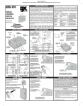
DESCRIPTION: The Delta-3 DR-2 digital receiver is a two-channel
wireless radio control designed for use with automatic garage/gate
operators and access control systems. The receiver can be
activated by any of the Delta-3 format transmitters. Receivers
must be mounted at least 8 feet apart.
The Delta-3 radio format provides 256 different digital codes. The
codes are set using the 8-position coding switches in the units.
DIGITAL
RECEIVER
DR2
Code Setting
Instructions
✶ CAUTION: All transmitters and receivers should be
recoded by the installer prior to operation.
In order to avoid the possibility of duplicating codes in adjacent
systems, factory set codes should not be used. In addition, among
the valid codes available, four others should not be used. These
include: all keys set ON or OFF and keys set alternating ON/OFF.
Activate each transmitter to test the equipment.
☞ WARNING! BE SURE DOOR OR GATE
AREAS ARE CLEAR OF OBSTRUCTIONS
INSTR,CODE SET,DR2B RCVR
Linear P/N: 200867 B
Size: 8.500" x 11.000"
Material: 20 Lb. Mead Bond
Ink: Black
Scale: 1-1
(800) 421-1587 • www.linearcorp.com
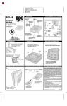
STEP 2 Code the receiver. Pick any combination of ON/ OFF
codes and set them on switch keys 2 through 8. Ignore Key 1. The
ON position is when the top of the switch is down. The OFF position
is when the top of the switch is up and the bottom is down. The
code set on Keys 2 through 8 on the receiver must now be matched
by all transmitters used in the system.
TRANSMITTER
#1
DO NOT SET
KEY #1
O
N
STEP 3 Code the transmitters. Remove the battery access door
located on the back of the transmitter case to set transmitter
codes. Keys 2 through 8 must match keys 2 through 8 on the
receiver. To access channel #1, set key #1 to ON. To access
channel #2, set key #1 to OFF. Refer to transmitter code set
instructions to code multi-button transmitters.
1
2
3
4
5
6
7
8
STEP 1 Locate coding switch. Locate the digital coding switch
which is recessed in the center of the back of the receiver case.
Note that the coding switch has eight keys. The keys are numbered
1 through 8. Key No. 1 is not used for coding the receiver; its
function is permanently wired on the circuit board.
SWITCHES IN
RECEIVER
24
V
RE
LA
Y
RA
PW DIO
R
THIS SWITCH
HAS 2, 3 & 6 ON
STEP 4A Connecting receiver (using transformer power). A
Model 524 transformer can be used to power the receiver when
connecting receiver to any operator. Connect as shown, then plug
the transformer into a convenient (unswitched) 110 VAC outlet.
TRANSMITTER
#2
MATCH
2-8
MATCH
2-8
3
2 24 VAC
1 RELAY
COM
SILVER
COMMON
COPPER
N/O
RED
N/C
O
F
F
OPERATOR #2
OPERATOR #1
OPEN
KEY #1 ON
KEY #1 OFF
3 (+)
3 (+)
2 Relay
2 Relay
1 (-)
1 (-)
SET KEYS 2-8 TO CREATE RECEIVER CODE
TRIGGERS CH. 2
TRIGGERS CH. 1
CAUTION:
All transmitters and receivers should be recoded
by the installer prior to operation
3
2 24 VAC
1 RELAY
COM
SILVER
COMMON
When Linear’s digital transmitters and receivers
leave the factory, they are set to predetermined
codes — a separate code for each model.
COPPER
N/O
RED
N/C
OPERATOR #1
OPERATOR #2
3 (+)
3 (+)
2 Relay
2 Relay
1 (-)
1 (-)
MANUAL
PUSHBUTTON
MANUAL
PUSHBUTTON
MANUAL
PUSHBUTTON
LINEAR LIMITED WARRANTY
STEP 4B Connecting receiver (using operator power).
Connect the receiver to the garage door or gate operator as shown
in the diagram. Power will be supplied from the operator.
MANUAL
PUSHBUTTON
It is not advisable to set a code with all keys ON,
OFF, or alternating ON and OFF, because these
codes are too easy to duplicate.
This product is warranted to the consumer against defects in material and workmanship for one year from the
date of purchase. This warranty applies to first retail buyers of new devices. Warrantor will repair, or at its option,
replace, any device it finds that requires service under this warranty, and will return the repaired or replaced
device to the consumer at the warrantor’s cost. For warranty service and shipping instructions contact warrantor
at the address shown below. Devices must be sent to warrantor for service at owner’s expense. The remedies
provided by this warranty are exclusive. Implied warranties under state law are to the one year period of this
written warranty. Some states do not allow limitations on how long an implied warranty lasts, so the above
limitation may not apply to you. In order to be protected by this warranty, save your proof of purchase and send
copy with equipment should repair be required. This warranty gives you specific legal rights, and you may also
have other rights which vary from state to state.
All products returned for warranty service require a Return Product Authorization Number (RPA#).
Contact Linear Technical Services at 1-800-421-1587 for an RPA# and other important details.
IMPORTANT !!!
Linear radio controls provide a reliable communications link and fill an important need in portable wireless
signaling. However, there are some limitations which must be observed.
✶ For U.S. installations only: The radios are required to comply with FCC Rules and Regulations as Part 15
devices. As such, they have limited transmitter power and therefore limited range.
✶ A receiver cannot respond to more than one transmitted signal at a time and may be blocked by radio signals
that occur on or near their operating frequencies, regardless of code settings.
✶ Changes or modifications to the device may void FCC compliance.
✶ Infrequently used radio links should be tested regularly to protect against undetected interference or fault.
✶ A general knowledge of radio and its vagaries should be gained prior to acting as a wholesale distributor or
dealer, and these facts should be communicated to the ultimate users.
This device complies with FCC Rules Part 15 and IC Canada Rules and Regulations. Operation is subject to
the following two conditions: (1) This device may not cause harmful interference and (2) this device must accept
any interference received, including interference that may cause undesired operation.
Copyright © 1999 Linear Corporation
200867 B