Transcript
PRINTER’S INSTRUCTIONS:
INSTR,INSTL,DXR-701A - LINEAR P/N: 220463 A - INK: BLACK - MATERIAL: 20 LB. MEAD BOND - SIZE: 11.000” X 8.500” - SCALE: 1-1
DXR-701
PRODUCT DESCRIPTION
The DXR-701 is a digital receiver with an isolated relay output designed for use
with Linear’s DX Format transmitters. This receiver can be used in a variety
of remote control applications. When the receiver detects a signal from a
transmitter programmed into its memory, the relay output activates. The relay
has four optional output configurations.
BY
SINGLECHANNEL
DIGITAL
RECEIVER
In a typical installation, the receiver is connected to an alarm control panel, door
strike, camera, high current relay or some other device. A transmitter is used to
activate or control the device. The receiver should be mounted with the supplied
mounting bracket indoors or inside a weather resistant non-metallic housing.
The digital DX code format features over a million possible codes. The DX
transmitters are precoded at the factory to unique codes, so no field coding
is required. Receivers must be programmed to the transmitter’s code before
system testing and operation. Up to 32 transmitters can be programmed
into the receiver’s memory. The memory is retained, even without power.
The unit can be powered from a 11-17 VDC or 12-16 VAC power source. The
relay’s normally open and normally closed contacts can switch up to 1 amp at
24 volts AC/DC.
Installation
Instructions
Cutting jumpers select how the relay activates. The factory setting causes
the relay to engage for four seconds each activation. Optionally, the relay
can be set to engage for one second, toggle on with one activation then off
with the next, or latch engaged until reset by pressing the program button.
(760) 438-7000 • FAX (760) 438-7043
USA & Canada (800) 421-1587 & (800) 392-0123
Toll Free FAX (800) 468-1340
www.linearcorp.com
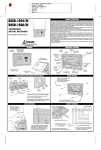
DXR-701 FEATURES
ANTENNA
POWER
TERMINALS
RELAY
TERMINALS
NOTE:
IF RELAY OPTION IS GOING TO
BE CHANGED: REMOVE POWER,
CUT JUMPERS, APPLY POWER,
ERASE MEMORY, THEN REPROGRAM ALL TRANSMITTERS
PROGRAM
BUTTON
N.O. COM N.C.
COM
N.O.
ALARM PANEL
ALARM PANEL CONNECTION
1 SECOND RELAY OPTION
DXR-701
TERMINALS
N.C.
COM
N.O.
POWER
SUPPLY
SECURITY CAMERA CONNECTION
LATCHING RELAY OPTION
N.C.
STRIKE
POWER
XFMR
COM
LOAD
EXTERNAL
RELAY
N.O.
RADIO
POWER
XFMR
DOOR STRIKE CONNECTION
4 SECOND RELAY OPTION
CAMERA
& VCR
N.O.
DXR-701
TERMINALS
ELECTRIC
DOOR STRIKE
POWER
SUPPLY
EXTERNAL RELAY CONNECTION
TOGGLE RELAY OPTION
SYSTEM TESTING
1. ACTIVATE EACH TRANSMITTER,
ONE AT AT TIME.
2. LISTEN FOR RELAY CLICK IN
RECEIVER.
3. VERIFY THAT THE DEVICE CONNECTED
TO THE RECEIVER RESPONDS.
4. TEST PORTABLE TRANSMITTERS IN
VARIOUS LOCATIONS TO DETERMINE
SYSTEM PERFORMANCE.
LIGHTS FOR 3 SECONDS FOR
PROGRAMMING
CHECKING
MEMORY
PRESS UNTIL BLINK AND
RELEASE
BLINKS THE NUMBER OF
TRANSMITTERS IN MEMORY
ERASING
MEMORY
PRESS AND HOLD
THROUGH THE COUNT
AND HOLD FOR 4
SECONDS MORE
AFTER BLINKING COUNT. A
PAUSE THEN A SINGLE BLINK
AS MEMORY IS ERASED
SNAP RECEIVER
ONTO BRACKET
JUMPER WJ1
JUMPER WJ2
4 SECOND LATCH
SOLID
SOLID
1 SECOND LATCH
CUT
SOLID
LATCH UNTIL RESET ++
SOLID
CUT
TOGGLE ON AND OFF ++
CUT
CUT
PROGRAMMING MEMORY
COM
AUX.
POWER
PRESS AND RELEASE
1. PRESS AND RELEASE
PROGRAM BUTTON.
2. PROGRAM INDICATOR
WILL LIGHT IF THERE IS
ROOM IN MEMORY FOR
ANOTHER TRANSMITTER.
(32 TRANSMITTERS MAX.)
3. SEND SIGNAL FROM
TRANSMITTER, INDICATOR
WILL FLICKER AS SIGNAL IS
RECEIVED.
MOUNTING NOTES:
1. MOUNT RECEIVER AS HIGH AS
POSSIBLE FOR BEST RADIO RANGE
2. KEEP RECEIVER AWAY FROM METAL
OBJECTS THAT CAN DECREASE RADIO
RANGE BY SHIELDING THE SIGNAL
3. KEEP RECEIVER AWAY FROM
MOTORS, FANS AND OTHER
ELECTRICAL DEVICES THAT MAY
CAUSE INTERFERENCE AND REDUCE
RADIO RANGE
CORNER HOLE IS
SHARED FOR
LOCATIONS 2 & 3
BRACKET CAN
MOUNT IN THREE
PLACES
LOCATION 2
LOCATION 1
BE SURE POWER IS OFF WHEN CUTTING JUMPERS
TERMINAL CONNECTIONS
N.C.
PROGRAMMING
MEMORY
JUMPER
WJ1
++ CAN BE RESET BY PUSHING THE PROGRAM BUTTON ONCE
N.C. OR N.O.
ALARM
LOOP
RELEASES LATCHED
RELAY
USE SCREWS TO
ATTACH THE
MOUNTING
BRACKET
RECEIVER CIRCUIT BOARD
N.C.
NORMAL
OPERATION
JUMPER
WJ2
RELAY OPTION
PROGRAM INDICATOR
LIGHTS AS TRANSMITTERS
ARE RECEIVED, BLINKS AS
INTERFERENCE IS RECEIVED
MOUNTING RECEIVER
ANTENNA
DXR-701
TERMINALS
PROGRAM BUTTON
TERMINALS
OPEN CASE
WITH SMALL
SCREWDRIVER
DXR-701
TERMINALS
FUNCTION
RELAY OPTION JUMPERS
PROGRAM
INDICATOR
11-17 VDC
12-16 VAC
A nine-inch wire lead serves as the receiver’s antenna. The red program
indicator lights during RF reception. The installer can verify that signals are
being sent from transmitters and diagnose interference problems by viewing
the indicator. The indicator also lights during memory programming/erasing and
flashes to count the number of transmitters in memory. The program button and
indicator function as follows:
LOCATION 3
PULL ANTENNA
STRAIGHT
CHECKING MEMORY
1. PRESS PROGRAM BUTTON
AND HOLD FOR ABOUT TWO
SECONDS UNTIL INDICATOR
LIGHTS THEN RELEASE.
2. COUNT THE NUMBER OF
INDICATOR BLINKS, THIS IS
THE TOTAL NUMBER OF
TRANSMITTERS PROGRAMMED.
4. REPEAT THE ABOVE THREE
STEPS FOR EACH ADDITIONAL
TRANSMITTER.
NOTE:
THE RECEIVER CAN MEMORIZE
EACH TRANSMITTER MORE THAN
ONCE. TO PREVENT DUPLICATE
ENTRIES, PROGRAM EACH
TRANSMITTER INTO RECEIVER
ONLY ONCE.
ERASING MEMORY
1. PRESS PROGRAM BUTTON
AND CONTINUE TO HOLD IT
THROUGH THE COUNT OF THE
TRANSMITTERS.
2. CONTINUE TO HOLD THE
BUTTON AFTER THE COUNT
UNTIL THE INDICATOR BLINKS
ONE MORE TIME (ABOUT
FIVE SECONDS AFTER THE
COUNT).
3. ALL TRANSMITTERS
PROGRAMMED INTO MEMORY
WILL BE ERASED.
PUSH AND HOLD BUTTON
FOR FIVE SECONDS AFTER
THE TRANSMITTER COUNT
PUSH UNTIL
INDICATOR LIGHTS
NOTE: DO NOT CONTINUE TO PRESS
BUTTON OR MEMORY WILL BE ERASED
LINEAR LIMITED WARRANTY
This Linear product is warranted against defects in material and workmanship for twelve (12)
months. The Warranty Expiration Date is labeled on the product. This warranty extends only
to wholesale customers who buy direct from Linear or through Linear’s normal distribution
channels. Linear does not warrant this product to consumers. Consumers should inquire from
their selling dealer as to the nature of the dealer’s warranty, if any. There are no obligations or
liabilities on the part of Linear Corporation for consequential damages arising out of or in
connection with use or performance of this product or other indirect damages with respect
to loss of property, revenue, or profit, or cost of removal, installation, or reinstallation.
All implied warranties, including implied warranties for merchantability and implied warranties
for fitness, are valid only until Warranty Expiration Date as labeled on the product. This Linear
Corporation Warranty is in lieu of all other warranties express or implied.
All products returned for warranty service require a Return Product Authorization Number (RPA#).
Contact Linear Technical Service at 1-800-421-1587 for an RPA# and other important details.
IMPORTANT !!!
Linear radio controls provide a reliable communications link and fill an important need in portable
wireless signalling. However, there are some limitations which must be observed.
• For U.S. installations only: The radios are required to comply with FCC Rules and Regulations
as Part 15 devices. As such, they have limited transmitter power and therefore limited range.
• A receiver cannot respond to more than one transmitted signal at a time and may be blocked
by radio signals that occur on or near their operating frequencies, regardless of code settings.
• Changes or modifications to the device may void FCC compliance.
• Infrequently used radio links should be tested regularly to protect against undetected
interference or fault.
• A general knowledge of radio and its vagaries should be gained prior to acting as a wholesale
distributor or dealer, and these facts should be communicated to the ultimate users.
Copyright © 2002 Linear Corporation
220463 A