1
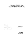
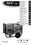
DEMO MANUAL DC101 SMART BATTERY CHARGER LT1511 Level 2, Smart Battery Charger Demo Board with SMBus Interface DESCRIPTIO U The DC101 board is a standalone Smart Battery charger that receives Charging Voltage(), Charging Current() and AlarmWarning() commands from the Smart Battery via the System Management Bus (SMBus) and sets charging current and voltage accordingly. The charger continu- ously monitors the built-in thermistor in the battery. The thermistor information is used by the software to inhibit charging at temperature extremes and to set charging strategy for different battery chemistries. , LTC and LT are registered trademarks of Linear Technology Corporation. W U WW PERFOR A CE SU ARY PARAMETER CONDITIONS Input Voltage MIN TYP MAX 16 24 27 UNIT V Input Current Hardware Limited 2 A Output Current Software Limited 0 2.5 A Output Voltage Software Limited 4 20 V Thermistor Resistance Ni-MH Battery Li-Ion Battery 30 1.5 kΩ kΩ 3 0.5 1 W U BLOCK DIAGRA A D BOARD PHOTO DC101 Smart Battery Charger R10 + FROM WALL CUBE SYSTEM CURRENT DC OUT 5V LT1129 5V µP SMB – 26 SHUTDOWN 14 PIC16C73 15 11 Q1 2 VOLTAGE PWM CURRENT PWM Q3 GND + LT ®1511 CHARGER Q2 Component Side 13 C SMBus CLOCK (SCL) D SMBus DATA (SDA) T THERMISTOR – BATTERY CONNECTOR 12 DC101 BD 1 2 24V 2A L1 20µH (+) (+) CLK CLK DATA DATA (T) (T) (–) (–) VOUT 4 5V + 3 C2 10µF 10V 1 2 3 4 5 6 7 8 9 10 C20 10µF 25V C18 10µF 10V 9 8 7 6 5 4 3 2 1 C16 100pF 50V 12 11 GND CLP 13 14 R12 100k 1/10W 0.1% R13 143k 1/10W 0.1% SPIN BAT 15 16 17 18 19 20 21 22 23 24 C11 10µF 25V R2 301Ω 1/10W 1% R15 21.5k 1/10W 0.1% C4 1µF 25V Q3 2N7002LT1 R1 3.32k 1/10W 1% R9 100k 5V Q2 2N7002LT1 C15 33pF C14 33pF R7 3.32k 1% R18 1k 1/10W 1% SHUTDOWN Y1 4MHz R4 3.32k 1% BOLD LINES INDICATE HIGH CURRENT PATHS Q1 2N7002LT1 R24 10k 5% Q4 MMBT3904LT1 R3 1k 1/10W 1% C3 33µF 25V UNLESS OTHERWISE SPECIFIED: 1. ALL RESISTANCES ARE IN OHMS, 1/10W, 5% 2. ALL CAPACITANCES ARE IN MICROFARADS, 50V, 10% C6 0.047µF C7 0.015µF 25V 5% R19 200Ω 1/10W 1% SENSE COMP1 COMP2 UVOUT OVP CLN VC PROG UV GND VCC3 GND VCC2 GND GND GND VCC1 U2 LT1511 C10 10µF 25V R17 1.05k 1/10W 1% BOOST SW GND C8 0.1µF 10 R14 330Ω TP1 TP2 TP3 TP4 TP5 + R23 22Ω 5V R20 200Ω 1/10W 1% R8 D4 0.033Ω BAS16LT1 1/2W R11 510Ω C5 1µF 25V D5 MBRS340T3 D3 MBRS340T3 R16 D6 BAS16LT1 3.32k R10 1/10W 0.05Ω 1% 1/2W 2 GND TAB VIN C9 0.47µF 25V C9 0.1µF DC IN SMART BATTERY CONNECTOR J1 AMP-787441-1 C12 10µF 25V E2 E1 J2 CENTER POST IS POSITIVE C17 0.1µF 1 U3 LT1129IST-5 Smart Battery Charger with SMBus Interface MCLR – SDA RC5 RC6 RC7 VSS VDD RB0/INT RB1 RB2 RB3 RB4 RB5 RB6 RB7 U1 PIC16C73-20PS SCL CCP1 CCP2 RCO OSC2 OSC1 VSS RA5/AN4 RA4 RA3/AN3 RA2/AN2 RA1/AN1 RA0/AN0 S1 5V R21 22k 5% 5V R22 22k 5% 5V 15 16 17 18 19 20 21 22 23 24 25 26 27 28 R25 22k 5% CHARGER ADJUSTMENT RANGE PWM1: 3FFh = 22.4V 000h = 6V PWM2:3FFh = 4.1A 000h = 0A 14 13 12 11 10 9 8 7 6 5 4 3 2 1 R26 10k RESET 5V INT SMBCLK SMBDATA R5 330Ω E7 E5 E6 D1 RED (SMB) 5V RESET DC101 SD 1 2 3 4 5 6 7 8 9 10 11 12 JPR1 C1 0.1µF D2 GRN (µP) E3 E4 R6 330Ω DC OUT DEMO MANUAL DC101 SMART BATTERY CHARGER W W SCHE ATIC DIAGRA DEMO MANUAL DC101 SMART BATTERY CHARGER W PACKAGE DIAGRA TOP VIEW GND 1 24 GND SW 2 23 GND BOOST 3 22 VCC1 GND 4 21 VCC2 GND 5 20 VCC3 UV 6 19 PROG GND 7 18 VC OVP 8 17 UVOUT CLP 9 16 GND CLN 10 15 COMP2 COMP1 11 14 BAT SENSE 12 13 SPIN LT1511CSW SW PACKAGE 24-LEAD PLASTIC SO WIDE PARTS LIST REFERENCE DESIGNATOR QUANTITY PART NUMBER DESCRIPTION VENDOR TELEPHONE C1, C8, C17, C19 4 12065C104KATMA 0.1µF 50V Chip Capacitor AVX (803) 946-0362 C2, C18 2 TAJB106M010 10µF 10V Tantalum Capacitor AVX (207) 282-5111 C3 1 12063G334ZAT2 0.33µF 25V Chip Capacitor AVX (803) 946-0362 C4, C5 2 12063G105ZATMA 1µF 25V Chip Capacitor AVX (803) 946-0362 C6 1 12065C473KAT 0.047µF 50V 10% Chip Capacitor AVX (803) 946-0362 C7 1 12063C153KAT2 0.015µF 25V 5% Chip Capacitor AVX (803) 946-0362 C9 1 12063G474ZAT2 0.47µF 25V Chip Capacitor AVX C10, C11, C12, C20 4 THCS50E1E106Z 10µF 25V Ceramic Capacitor Marcon C14, C15 2 1206A330KAT2 33pF 50V Chip Capacitor AVX (803) 946-0362 C16 1 VJ1206A101KXA 100pF 50V Chip Capacitor Vitramon (203) 268-6261 D1 1 SF1-BR Red LED Data Display Product (800) 421-6815 D2 1 SF1-G Green LED Data Display Product (800) 421-6815 D3, D5 2 MBRS340T3 Diode Motorola (602) 244-3576 D4, D6 2 BAS16LT1 Diode Motorola (602) 244-3576 J1 1 AMP-787441-1 Connector AMP (717) 780-4409 (803) 946-0362 (847) 696-2000 x374 J2 1 CUI-PJ-002A Connector Cui-Stack (503) 643-4899 JPR1 1 3801S-12-G1 12-Pin Header Jumper Comm Con Conn. (818) 301-4200 L1 1 CTX20-4 20µH Inductor Coiltronics (407) 241-7876 Q1,Q2, Q3 3 2N7002LT N-Channel MOSFET Motorola (602) 244-3576 Q4 1 MMBT3904LT1 NPN Transistor Motorola (602) 244-4342 R1, R4, R16 3 CR32-3321F-T 3.32k 1/8W 1% Resistor AVX (803) 946-0524 R2 1 CR32-3010F-T 301Ω 1/8W 1% Resistor AVX (803) 946-0524 R3, R18 2 CR32-1001F-T 1k 1/8W 1% Resistor AVX (803) 946-0524 3 DEMO MANUAL DC101 SMART BATTERY CHARGER PARTS LIST REFERENCE DESIGNATOR QUANTITY PART NUMBER DESCRIPTION VENDOR 330Ω 1/8W 5% Resistor AVX TELEPHONE R5, R6, R14 3 CR32-331J-T (803) 946-0524 R7 1 BCR1/8-3322F-T 33.2k 1/8W 1% Resistor Beckman (714) 447-2345 R8 1 LR2010-01-R033-J 0.033Ω 1/2W 5% Resistor IRC (512) 992-7900 R9 1 CR32-104J-T 100k 1/8W 5% Resistor AVX (803) 946-0524 R10 1 LR2010-01-R050-J 0.05Ω 1/2W 5% Resistor IRC (512) 992-7900 R11 1 CR32-511J-T 510Ω 1/8W 5% Resistor AVX (803) 946-0524 R12 1 W1206R-03-1003-B 100k 1/8W 0.1% Resistor IRC (512) 992-7900 R13 1 W1206R-03-1433-B 143k 1/10W 0.1% Resistor IRC (512) 992-7900 R15 1 W1206R-03-2152-B 21.5k 1/10W 0.1% Resistor IRC (512) 992-7900 R17 1 CR32-1051F-T 1.05k 1/8W 1% Resistor AVX (803) 946-0524 R19, R20 2 CR32-2000F-T 200Ω 1/8W 1% Resistor AVX (803) 946-0524 R21, R22, R25 3 CR32-223J-T 22k 1/10W 5% Resistor AVX (803) 946-0524 R23 1 CR32-220J-T 22Ω 1/10W 5% Resistor AVX (803) 946-0524 R24, R26 2 CR1206-103J 10k 1/8W 5% Resistor Dale (605) 665-9301 S1 1 MJTP1230 PB Switch MORS-ASC (617) 246-1007 TP1 to TP5, E1 to E7 12 1502-2 Turret Testpoint Keystone (718) 956-8900 U1 1 PIC16C73-20SP Microcontroller IC Microchip (602) 786-7200 U2 1 LT1511 Battery Charger IC LTC (408) 432-1900 U3 1 LT1129IST-5 Voltage Regulator IC LTC (408) 432-1900 XU1 1 7167-14-G2 Sockets IC Comm Con (818) 301-4200 Y1 1 MA-505-4.00M-C2 4MHz Crystal Epson (USA) (310) 787-6300 U OPERATIO Input Voltage: The nominal input voltage of the board is 24V DC. The input voltage must be higher than the battery voltage by a minimum of 3V. The minimum input voltage is 16V, limited by the undervoltage lockout circuit in the LT1511 and set by resistors R16, R17 and R18. The highest input voltage is 27.4V, limited by the maximum input voltage of the LT1511. The input is protected against reverse polarity up to 30V. Input Current: The sum of the system current and the charger input current is limited by the LT1511 to 2A. When both the system current and the charger input current requirements are high, the charger reduces the charging current to meet the 2A current limit. 4 Red LED: A red LED indicates SMBus activity. It lights up for about 1 second when the charger recognizes its own address (12 hex) on the SMBus. Green LED: A flashing green LED indicates microprocessor activity and charger status. Fast blinking (approximately 8Hz) indicates normal microprocessor activity and either trickle charge or shutdown charger status. After valid voltage and current data have been received, the blinking speed of the LED slows down to about 2Hz, indicating normal charging. DEMO MANUAL DC101 SMART BATTERY CHARGER U OPERATIO Battery Removal, Thermistor Measurements: The charger periodically checks the thermistor in the battery through the T-terminal. When the thermistor is out of normal operating temperature range, the charger switches to trickle charge mode and increases the flashing frequency of the green LED to indicate an abnormal charging condition. When the resistance of the thermistor is in the 500Ω < RTH < 1.5k range, the charger assumes a LiIon battery is at the output. Instead of trickle charging the battery it shuts down the charger until a valid voltage and current request arrives from the battery. An open thermistor forces the charger into trickle charge mode and the charger disregards data on the SMBus. System Management Bus (SMBus) When charge in the Smart Battery (SB) drops below 85% of the nominal capacity, it initiates communication over the SMBus every 64 seconds. After sending a START sequence, the battery addresses the Smart Battery charger and waits for an acknowledgment (ACK) from it. If the charger fails to acknowledge the word, the battery terminates further communication by placing a STOP sequence onto the SMBus. If the charger acknowledges (ACK) the reception of the first word, the battery continues the communication sequence and sends six more words to the charger. The complete current and voltage request communication sequence is as follows: START address (12 hex) Charging Current() command code (14 hex), current_LSB current_MSB, address (12 hex) Charging Voltage() command code (15 hex) voltage_LSB voltage_MSB STOP The idealized SMBus waveforms shown in Figure 1 illustrate SMBus communication between the battery and the charger. The first seven bits after the START sequence are the battery address. The R/W bit tells the charger that the battery is attempting to write to the charger. During the acknowledge period (ACK), the charger becomes active and pulls the data line (SDA) low, indicating reception of a data word. When reception of the data word is not acknowledged by the charger, the battery terminates the communication by sending a STOP sequence to the bus. The clock pulses for the communication are always generated by the battery (BUS MASTER). “C” Source Code The latest version of “C” language source code, header file, code file and hex dump file is provided on a 3.5" disk. SDA SCLK 0 0 0 1 0 0 START 1 2 1 R/W ACK DC101 F01 0 = WRITE 1 = 1ST NIBBLE 2 = 2ND NIBBLE (TRUNCATED) THIS EXAMPLE = 12(H) Figure 1. SMBus Waveforms Indicating Battery Address 5 DEMO MANUAL DC101 SMART BATTERY CHARGER U OPERATIO INIT VARIABLES START INTERRUPT THERMISTOR OPEN 12C DATA RECEIVED Y DISABLE INTERRUPTS THERMISTOR TOO HOT A/D COUNTER = 0 Y Y TURN RED LED ON FOR 2 SEC RESET 12C POINTER Y PUT 12C DATA ON THE 12C STACK INCREMENT POINTER MEASURE THERMISTOR ENABLE INTERRUPTS ALARM WARNING ON STACK CHARGING CURRENT ON STACK Y Y SET ERROR FLAG SHUT DOWN CHARGER ERASE COMMAND LOAD IPWM ERASE COMMAND ENABLE CHARGER ERASE ERROR FLAG THERMISTOR IN RANGE Y RETURN FROM INTERRUPT THERMISTOR TOO COLD Y Y Li-Ion CHARGING VOLTAGE ON STACK Y LOAD VPWM ERASE COMMAND ENABLE CHARGER ERASE ERROR FLAG THERMISTOR SHORTED ERROR FLAG Y SET FAST BLINKING SET TRICKLE CHARGE SET ERROR FLAG SET SLOW BLINKING IF NO Li-Ion FLAG: INIT Li-Ion MODE ERASE ERROR FLAG IF Li-Ion FLAG SET: ERASE Li-Ion FLAG ERASE ERROR FLAG INIT Ni-MH MODE Figure 2. Software Flowchart 6 DEMO MANUAL DC101 SMART BATTERY CHARGER U W PCB LAYOUT A D FIL Component Side Silkscreen Component Side Component Side Solder Mask Information furnished by Linear Technology Corporation is believed to be accurate and reliable. However, no responsibility is assumed for its use. Linear Technology Corporation makes no representation that the interconnection of circuits as described herein will not infringe on existing patent rights. 7 DEMO MANUAL DC101 SMART BATTERY CHARGER U W PCB LAYOUT A D FIL Solder Side Solder Mask Solder Side U PC FAB DRAWI G H A H 0.150" H D G E H G A H B G H E B H H 3.019" H H C H H D D 0.150" 0.219" A F E A 0.150" 0.150" SYMBOL A B C D E F G H NUMBER DIAMETER OF HOLES 125 4 120 2 100 1 94 12 40 14 39 4 37 40 18 55 TOTAL HOLES 132 NOTES 1. MATERIAL: 2 LAYERS, 0.062" THICK. FR-4 GLASS EPOXY 2 OZ COPPER CLAD 2. ALL HOLES SHALL BE PLATED THROUGH 3. PLATE THROUGH HOLES WITH COPPER 0.0014 MIN THICKNESS. ALL HOLE SIZES IN HOLE TABLE ARE AFTER PLATING 4. SILKSCREEN: WITH WHITE EPOXY NONCONDUCTIVE INK 5. FINISH: SMOBC 6. SOLDER MASK: USE FILM PROVIDED, GREEN DC101 FD 2.744" 3.900" 8 Linear Technology Corporation LT/GP 0796 500 • PRINTED IN USA 1630 McCarthy Blvd., Milpitas, CA 95035-7417 (408) 432-1900 ● FAX: (408) 434-0507 ● TELEX: 499-3977 LINEAR TECHNOLOGY CORPORATION 1996