1
View Safety Info
SVM169-A
July, 2006
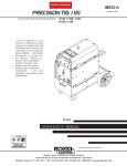
PRECISION TIG 185
For use with machines having Code Number : 11105 thru 11109
Return to Master TOC
View Safety Info
View Safety Info
Safety Depends on You
Return to Master TOC
Return to Master TOC
RETURN TO MAIN MENU
Lincoln arc welding and cutting
equipment is designed and built
with safety in mind. However,
your overall safety can be
increased by proper installation
. . . and thoughtful operation on
your part. DO NOT INSTALL,
OPERATE OR REPAIR THIS
EQUIPMENT WITHOUT READING THIS MANUAL AND THE
SAFETY PRECAUTIONS CONTAINED THROUGHOUT. And,
most importantly, think before
you act and be careful.
View Safety Info
Return to Master TOC
SERVICE MANUAL
Copyright © 2006 Lincoln Global Inc.
• World's Leader in Welding and Cutting Products •
• Sales and Service through Subsidiaries and Distributors Worldwide •
Cleveland, Ohio 44117-1199 U.S.A. TEL: 216.481.8100 FAX: 216.486.1751 WEB SITE: www.lincolnelectric.com
Return to Master TOC
i
i
SAFETY
WARNING
CALIFORNIA PROPOSITION 65 WARNINGS
Diesel engine exhaust and some of its constituents
are known to the State of California to cause cancer, birth defects, and other reproductive harm.
The Above For Diesel Engines
The engine exhaust from this product contains
chemicals known to the State of California to cause
cancer, birth defects, or other reproductive harm.
The Above For Gasoline Engines
ARC WELDING CAN BE HAZARDOUS. PROTECT YOURSELF AND OTHERS FROM POSSIBLE SERIOUS INJURY OR DEATH.
KEEP CHILDREN AWAY. PACEMAKER WEARERS SHOULD CONSULT WITH THEIR DOCTOR BEFORE OPERATING.
Return to Master TOC
Return to Master TOC
Return to Master TOC
Read and understand the following safety highlights. For additional safety information, it is strongly recommended that you
purchase a copy of “Safety in Welding & Cutting - ANSI Standard Z49.1” from the American Welding Society, P.O. Box 351040,
Miami, Florida 33135 or CSA Standard W117.2-1974. A Free copy of “Arc Welding Safety” booklet E205 is available from the
Lincoln Electric Company, 22801 St. Clair Avenue, Cleveland, Ohio 44117-1199.
BE SURE THAT ALL INSTALLATION, OPERATION, MAINTENANCE AND REPAIR PROCEDURES ARE
PERFORMED ONLY BY QUALIFIED INDIVIDUALS.
FOR ENGINE
powered equipment.
1.h. To avoid scalding, do not remove the
radiator pressure cap when the engine is
hot.
1.a. Turn the engine off before troubleshooting and maintenance
work unless the maintenance work requires it to be running.
____________________________________________________
1.b. Operate engines in open, well-ventilated
areas or vent the engine exhaust fumes
outdoors.
____________________________________________________
1.c. Do not add the fuel near an open flame welding arc or when the engine is running. Stop
the engine and allow it to cool before refueling to prevent spilled fuel from vaporizing on
contact with hot engine parts and igniting. Do
not spill fuel when filling tank. If fuel is spilled,
wipe it up and do not start engine until fumes
have been eliminated.
____________________________________________________
1.d. Keep all equipment safety guards, covers and devices in position and in good repair.Keep hands, hair, clothing and tools
away from V-belts, gears, fans and all other moving parts
when starting, operating or repairing equipment.
____________________________________________________
1.e. In some cases it may be necessary to remove safety
guards to perform required maintenance. Remove
guards only when necessary and replace them when the
maintenance requiring their removal is complete.
Always use the greatest care when working near moving
parts.
___________________________________________________
1.f. Do not put your hands near the engine fan.
Do not attempt to override the governor or
idler by pushing on the throttle control rods
while the engine is running.
ELECTRIC AND
MAGNETIC FIELDS
may be dangerous
2.a. Electric current flowing through any conductor causes
localized Electric and Magnetic Fields (EMF). Welding
current creates EMF fields around welding cables and
welding machines
2.b. EMF fields may interfere with some pacemakers, and
welders having a pacemaker should consult their physician
before welding.
2.c. Exposure to EMF fields in welding may have other health
effects which are now not known.
2.d. All welders should use the following procedures in order to
minimize exposure to EMF fields from the welding circuit:
2.d.1. Route the electrode and work cables together - Secure
them with tape when possible.
2.d.2. Never coil the electrode lead around your body.
2.d.3. Do not place your body between the electrode and
work cables. If the electrode cable is on your right
side, the work cable should also be on your right side.
2.d.4. Connect the work cable to the workpiece as close as
possible to the area being welded.
___________________________________________________
1.g. To prevent accidentally starting gasoline engines while
turning the engine or welding generator during maintenance
work, disconnect the spark plug wires, distributor cap or
magneto wire as appropriate.
2.d.5. Do not work next to welding power source.
Mar ‘95
PRECISION TIG 185
Return to Master TOC
Return to Master TOC
ii
ELECTRIC SHOCK can kill.
ARC RAYS can burn.
3.a. The electrode and work (or ground) circuits
are electrically “hot” when the welder is on.
Do not touch these “hot” parts with your bare
skin or wet clothing. Wear dry, hole-free
gloves to insulate hands.
4.a. Use a shield with the proper filter and cover
plates to protect your eyes from sparks and
the rays of the arc when welding or observing
open arc welding. Headshield and filter lens
should conform to ANSI Z87. I standards.
3.b. Insulate yourself from work and ground using dry insulation.
Make certain the insulation is large enough to cover your full
area of physical contact with work and ground.
4.b. Use suitable clothing made from durable flame-resistant
material to protect your skin and that of your helpers from
the arc rays.
In addition to the normal safety precautions, if welding
must be performed under electrically hazardous
conditions (in damp locations or while wearing wet
clothing; on metal structures such as floors, gratings or
scaffolds; when in cramped positions such as sitting,
kneeling or lying, if there is a high risk of unavoidable or
accidental contact with the workpiece or ground) use
the following equipment:
• Semiautomatic DC Constant Voltage (Wire) Welder.
• DC Manual (Stick) Welder.
• AC Welder with Reduced Voltage Control.
4.c. Protect other nearby personnel with suitable, non-flammable
screening and/or warn them not to watch the arc nor expose
themselves to the arc rays or to hot spatter or metal.
3.c. In semiautomatic or automatic wire welding, the electrode,
electrode reel, welding head, nozzle or semiautomatic
welding gun are also electrically “hot”.
3.d. Always be sure the work cable makes a good electrical
connection with the metal being welded. The connection
should be as close as possible to the area being welded.
3.e. Ground the work or metal to be welded to a good electrical
(earth) ground.
3.f. Maintain the electrode holder, work clamp, welding cable and
welding machine in good, safe operating condition. Replace
damaged insulation.
Return to Master TOC
ii
SAFETY
3.g. Never dip the electrode in water for cooling.
3.h. Never simultaneously touch electrically “hot” parts of
electrode holders connected to two welders because voltage
between the two can be the total of the open circuit voltage
of both welders.
3.i. When working above floor level, use a safety belt to protect
yourself from a fall should you get a shock.
3.j. Also see Items 6.c. and 8.
FUMES AND GASES
can be dangerous.
5.a. Welding may produce fumes and gases
hazardous to health. Avoid breathing these
fumes and gases.When welding, keep
your head out of the fume. Use enough
ventilation and/or exhaust at the arc to keep
fumes and gases away from the breathing zone. When
welding with electrodes which require special
ventilation such as stainless or hard facing (see
instructions on container or MSDS) or on lead or
cadmium plated steel and other metals or coatings
which produce highly toxic fumes, keep exposure as
low as possible and below Threshold Limit Values (TLV)
using local exhaust or mechanical ventilation. In
confined spaces or in some circumstances, outdoors, a
respirator may be required. Additional precautions are
also required when welding on galvanized steel.
5.b. Do not weld in locations near chlorinated hydrocarbon vapors
coming from degreasing, cleaning or spraying operations.
The heat and rays of the arc can react with solvent vapors to
form phosgene, a highly toxic gas, and other irritating products.
5.c. Shielding gases used for arc welding can displace air and
cause injury or death. Always use enough ventilation,
especially in confined areas, to insure breathing air is safe.
5.d. Read and understand the manufacturer’s instructions for this
equipment and the consumables to be used, including the
material safety data sheet (MSDS) and follow your
employer’s safety practices. MSDS forms are available from
your welding distributor or from the manufacturer.
5.e. Also see item 1.b.
Return to Master TOC
Mar ‘95
PRECISION TIG 185
SAFETY
Return to Master TOC
iii
WELDING SPARKS can
cause fire or explosion.
6.a. Remove fire hazards from the welding area.
If this is not possible, cover them to prevent
the welding sparks from starting a fire.
Remember that welding sparks and hot
materials from welding can easily go through small cracks
and openings to adjacent areas. Avoid welding near
hydraulic lines. Have a fire extinguisher readily available.
6.b. Where compressed gases are to be used at the job site,
special precautions should be used to prevent hazardous
situations. Refer to “Safety in Welding and Cutting” (ANSI
Standard Z49.1) and the operating information for the
equipment being used.
Return to Master TOC
6.c. When not welding, make certain no part of the electrode
circuit is touching the work or ground. Accidental contact can
cause overheating and create a fire hazard.
6.d. Do not heat, cut or weld tanks, drums or containers until the
proper steps have been taken to insure that such procedures
will not cause flammable or toxic vapors from substances
inside. They can cause an explosion even though they have
been “cleaned”. For information, purchase “Recommended
Safe Practices for the Preparation for Welding and Cutting of
Containers and Piping That Have Held Hazardous
Substances”, AWS F4.1 from the American Welding Society
(see address above).
6.e. Vent hollow castings or containers before heating, cutting or
welding. They may explode.
6.f. Sparks and spatter are thrown from the welding arc. Wear oil
free protective garments such as leather gloves, heavy shirt,
cuffless trousers, high shoes and a cap over your hair. Wear
ear plugs when welding out of position or in confined places.
Always wear safety glasses with side shields when in a
welding area.
Return to Master TOC
iii
6.g. Connect the work cable to the work as close to the welding
area as practical. Work cables connected to the building
framework or other locations away from the welding area
increase the possibility of the welding current passing
through lifting chains, crane cables or other alternate circuits.
This can create fire hazards or overheat lifting chains or
cables until they fail.
6.h. Also see item 1.c.
CYLINDER may explode
if damaged.
7.a. Use only compressed gas cylinders
containing the correct shielding gas for the
process used and properly operating
regulators designed for the gas and
pressure used. All hoses, fittings, etc. should be suitable for
the application and maintained in good condition.
7.b. Always keep cylinders in an upright position securely
chained to an undercarriage or fixed support.
7.c. Cylinders should be located:
• Away from areas where they may be struck or subjected to
physical damage.
• A safe distance from arc welding or cutting operations and
any other source of heat, sparks, or flame.
7.d. Never allow the electrode, electrode holder or any other
electrically “hot” parts to touch a cylinder.
7.e. Keep your head and face away from the cylinder valve outlet
when opening the cylinder valve.
7.f. Valve protection caps should always be in place and hand
tight except when the cylinder is in use or connected for
use.
7.g. Read and follow the instructions on compressed gas
cylinders, associated equipment, and CGA publication P-l,
“Precautions for Safe Handling of Compressed Gases in
Cylinders,” available from the Compressed Gas Association
1235 Jefferson Davis Highway, Arlington, VA 22202.
FOR ELECTRICALLY
powered equipment.
8.a. Turn off input power using the disconnect
switch at the fuse box before working on
the equipment.
8.b. Install equipment in accordance with the U.S. National
Electrical Code, all local codes and the manufacturer’s
recommendations.
8.c. Ground the equipment in accordance with the U.S. National
Electrical Code and the manufacturer’s recommendations.
Return to Master TOC
Mar ‘95
PRECISION TIG 185
SAFETY
Return to Master TOC
a. Les circuits à l’électrode et à la piéce sont sous tension
quand la machine à souder est en marche. Eviter toujours
tout contact entre les parties sous tension et la peau nue
ou les vétements mouillés. Porter des gants secs et sans
trous pour isoler les mains.
b. Faire trés attention de bien s’isoler de la masse quand on
soude dans des endroits humides, ou sur un plancher metallique ou des grilles metalliques, principalement dans
les positions assis ou couché pour lesquelles une grande
partie du corps peut être en contact avec la masse.
c. Maintenir le porte-électrode, la pince de masse, le câble de
soudage et la machine à souder en bon et sûr état defonctionnement.
d.Ne jamais plonger le porte-électrode dans l’eau pour le
refroidir.
e. Ne jamais toucher simultanément les parties sous tension
des porte-électrodes connectés à deux machines à souder
parce que la tension entre les deux pinces peut être le total
de la tension à vide des deux machines.
f. Si on utilise la machine à souder comme une source de
courant pour soudage semi-automatique, ces precautions
pour le porte-électrode s’applicuent aussi au pistolet de
soudage.
Return to Master TOC
Return to Master TOC
Pour votre propre protection lire et observer toutes les instructions
et les précautions de sûreté specifiques qui parraissent dans ce
manuel aussi bien que les précautions de sûreté générales suivantes:
Return to Master TOC
iv
PRÉCAUTIONS DE SÛRETÉ
Sûreté Pour Soudage A L’Arc
1. Protegez-vous contre la secousse électrique:
2. Dans le cas de travail au dessus du niveau du sol, se protéger
contre les chutes dans le cas ou on recoit un choc. Ne jamais
enrouler le câble-électrode autour de n’importe quelle partie du
corps.
3. Un coup d’arc peut être plus sévère qu’un coup de soliel, donc:
iv
zones où l’on pique le laitier.
6. Eloigner les matériaux inflammables ou les recouvrir afin de
prévenir tout risque d’incendie dû aux étincelles.
7. Quand on ne soude pas, poser la pince à une endroit isolé de
la masse. Un court-circuit accidental peut provoquer un
échauffement et un risque d’incendie.
8. S’assurer que la masse est connectée le plus prés possible de
la zone de travail qu’il est pratique de le faire. Si on place la
masse sur la charpente de la construction ou d’autres endroits
éloignés de la zone de travail, on augmente le risque de voir
passer le courant de soudage par les chaines de levage,
câbles de grue, ou autres circuits. Cela peut provoquer des
risques d’incendie ou d’echauffement des chaines et des
câbles jusqu’à ce qu’ils se rompent.
9. Assurer une ventilation suffisante dans la zone de soudage.
Ceci est particuliérement important pour le soudage de tôles
galvanisées plombées, ou cadmiées ou tout autre métal qui
produit des fumeés toxiques.
10. Ne pas souder en présence de vapeurs de chlore provenant
d’opérations de dégraissage, nettoyage ou pistolage. La
chaleur ou les rayons de l’arc peuvent réagir avec les vapeurs
du solvant pour produire du phosgéne (gas fortement toxique)
ou autres produits irritants.
11. Pour obtenir de plus amples renseignements sur la sûreté, voir
le code “Code for safety in welding and cutting” CSA Standard
W 117.2-1974.
PRÉCAUTIONS DE SÛRETÉ POUR
LES MACHINES À SOUDER À
TRANSFORMATEUR ET À
REDRESSEUR
a. Utiliser un bon masque avec un verre filtrant approprié ainsi
qu’un verre blanc afin de se protéger les yeux du rayonnement de l’arc et des projections quand on soude ou
quand on regarde l’arc.
b. Porter des vêtements convenables afin de protéger la peau
de soudeur et des aides contre le rayonnement de l‘arc.
c. Protéger l’autre personnel travaillant à proximité au
soudage à l’aide d’écrans appropriés et non-inflammables.
1. Relier à la terre le chassis du poste conformement au code de
l’électricité et aux recommendations du fabricant. Le dispositif
de montage ou la piece à souder doit être branché à une
bonne mise à la terre.
4. Des gouttes de laitier en fusion sont émises de l’arc de
soudage. Se protéger avec des vêtements de protection libres
de l’huile, tels que les gants en cuir, chemise épaisse, pantalons sans revers, et chaussures montantes.
3. Avant de faires des travaux à l’interieur de poste, la debrancher à l’interrupteur à la boite de fusibles.
2. Autant que possible, I’installation et l’entretien du poste seront
effectués par un électricien qualifié.
4. Garder tous les couvercles et dispositifs de sûreté à leur place.
5. Toujours porter des lunettes de sécurité dans la zone de
soudage. Utiliser des lunettes avec écrans lateraux dans les
PRECISION TIG 185
v
v
RETURN TO MAIN MENU
MASTER TABLE OF CONTENTS FOR ALL SECTIONS
Safety . . . . . . . . . . . . . . . . . . . . . . . . . . . . . . . . . . . . . . . . . . . . . . . . . . . . . . . .
i-iv
Installation . . . . . . . . . . . . . . . . . . . . . . . . . . . . . . . . . . . . . . . . . . . . . . . . . . . . Section A
Operation . . . . . . . . . . . . . . . . . . . . . . . . . . . . . . . . . . . . . . . . . . . . . . . . . . . . . Section B
Accessories . . . . . . . . . . . . . . . . . . . . . . . . . . . . . . . . . . . . . . . . . . . . . . . . . . Section C
Maintenance . . . . . . . . . . . . . . . . . . . . . . . . . . . . . . . . . . . . . . . . . . . . . . . . . . Section D
Theory of Operation . . . . . . . . . . . . . . . . . . . . . . . . . . . . . . . . . . . . . . . . . . . . Section E
Troubleshooting and Repair . . . . . . . . . . . . . . . . . . . . . . . . . . . . . . . . . . . . . Section F
Electrical Diagrams . . . . . . . . . . . . . . . . . . . . . . . . . . . . . . . . . . . . . . . . . . . . Section G
Parts Manual . . . . . . . . . . . . . . . . . . . . . . . . . . . . . . . . . . . . . . . . . . . . . . . . . .P499 Series
PRECISION TIG 185
Return to Master TOC
Section A-1
TABLE OF CONTENTS
- INSTALLATION SECTION -
Section A-1
Installation ..............................................................................................................Section A
Technical Specifications.....................................................................................A-2/A-3
Safety Precautions ....................................................................................................A-4
Location.....................................................................................................................A-4
Grinding ..............................................................................................................A-4
Return to Master TOC
Stacking ..............................................................................................................A-4
Lifting and Moving ..............................................................................................A-4
Tilting ..................................................................................................................A-4
Environmental Rating..........................................................................................A-4
Machine Grounding and High Frequency Interference Protection ...........................A-4
Input Connections.....................................................................................................A-5
Input Reconnect Procedure ......................................................................................A-6
Output Connections ..................................................................................................A-6
Connections for TIG Welding .............................................................................A-6
TIG Torch Connection .................................................................................A-6
Work Cable Connection ..............................................................................A-7
Return to Master TOC
Return to Master TOC
Shielding Gas Connection...........................................................................A-7
Remote Control Connection........................................................................A-7
Connections for Stick Welding..................................................................................A-7
Stick Electrode Cable and Work Cable Connection ..........................................A-7
PRECISION TIG 185
Return to Master TOC
Return to Section TOC
A-2
A-2
INSTALLATION
TECHNICAL SPECIFICATIONS - PRECISION TIG 185 (K2345-1AND K2347-1,-2)
INPUT - SINGLE PHASE ONLY
Standard Voltage
Input Current at Rated Output
208/230/1/60
35A / 32A Effective
and 70A / 64A Maximum
OUTPUT RANGE
Output Current
Range
Maximum Open
Circuit Voltage
7-185 Amps (AC)
5-185 Amps (DC)
(STICK AND TIG)
Type of Output
CC (Constant Current)
AC/DC
AC OCV: 75
DC OCV: 59
Return to Master TOC
Return to Section TOC
RATED OUTPUT
Duty Cycle
GTAW 15% Duty Cycle
100% Duty Cycle
Amps
185A AC/DC
90A AC/DC (BAL)
70A AC (AUTO-BAL)
Volts at Rated Amperes
15.2 V AC/DC
14.1 V AC/DC
13.8 V AC/DC
SMAW 15% Duty Cycle
100% Duty Cycle
185A AC/DC125
90A AC/DC
27.4 V AC/DC
23.6 V AC/DC
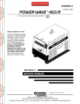
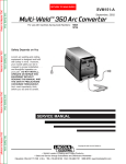
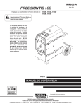
Chart gives max. rated Output Amps @% Duty Cycle (Based on a 10 minute cycle)
(Example; 110A@60% for AC/DC Stick and Balance TIG)
(1)
OUTPUT % DUTY CYCLE
90%
208/230v Model: AC/DC Stick & DC TIG
(AC TIG with #6-3 input cable)
460/575v Model: AC/DC Stick & AC/DC TIG
380/415v Model: AC/DC Stick &
DC/AC Auto-Bal.TIG
80%
70%
60%
208/230v Model: AC TIG using 230v input
380/415v Model: AC TIG (Max. Penetration)
50%
40%
208/230v Model: AC TIG using 208v input
30%
20%
10%
Return to Master TOC
0%
Return to Section TOC
input supply
100%
Return to Master TOC
Return to Section TOC
Using standard #8-3 input cable for protected
50
70
90
110
130
150
170
190
OUTPUT AMPS
(1)
Wiring and protection based on the 2002 U.S. National Electric Code:
Use a Super Lag type fuse or circuit breaker with a delay in tripping action.
Models with NEMA 6-50P plug may be used with a 50 amp protected 6-50R receptacle, or
with a maximum 70 amp protected 6-50R receptacle if dedicated for the welder.
PRECISION TIG 185
Return to Master TOC
Return to Section TOC
A-3
A-3
INSTALLATION
TECHNICAL SPECIFICATIONS - CANADIAN (K2345-2), INTERNATIONAL K2346-1)
K2345-2 INPUT (at Rated Output)
Voltage/Phase/Freq.
Current
Power Factor
Idle Current
460/575/1/60
16 A/13 A Effective
32 A/26 A Max.
0.62 Min.
1.3 A/1.0 A Max.
Voltage/Phase/Freq.
Current
Power Factor
Idle Current
380/400-415/1/50/60
19 A/18 A Effective
39 A/37 A Max.
0.62 Min.
1.3 A/1.0 A Max.
N80
Return to Master TOC
Return to Section TOC
K2346-1 INPUT (at Rated Output)
OUTPUT RANGE
Max. OCV.
Weld Current
Output Type
74 V (AC)
59 V (DC)
7-185 A (AC)
5-185 A (DC).
CC (Constant Current)
AC or DC
RATED OUTPUT
Return to Master TOC
Return to Master TOC
Return to Section TOC
Return to Section TOC
Process Duty Cycle*.
SMAW
15%
100%
GTAW
15%
100%
*
Weld Current
Weld Voltage (NEMA)
185 A AC/DC
90 A AC/DC
27.4 V
23.6 V
185 A AC/DC
90 A AC/DC (Auto-Bal.)
15.2 V
14.1 V
Based on a 10 minute cycle.
PHYSICAL DIMENSIONS(2)
MODEL
HEIGHT
WIDTH
DEPTH
WEIGHT
Machine Only
(K2345-1,-2)
(K2346-1)
Ready-Pak
(K2347-1)
20.71 in.
526 mm
14.48 in.
368 mm
25.62 in.
751 mm
Approx. 192 lbs.
87.1 kgs
20.71 in.
526 mm
14.48 in.
368 mm
25.62 in.
651 mm
Approx. 212lbs..
96.2 kgs.
Ready-PakW/Cart
(K2347-2)
31.24 in.
794 mm
19.81 in.
503 mm
38.01 in.
966 mm
Approx. 258lbs.
117.0 kgs.
(2) Dimensions are without Lift Eyebolt and Torch Holder
PRECISION TIG 185
Return to Master TOC
Return to Section TOC
A-4
SAFETY PRECAUTIONS
Read entire installation section before starting
installation.
WARNING
ELECTRIC SHOCK can kill.
• Only qualified personnel should
perform this installation.
• Turn the input power OFF at the
disconnect switch or fuse box
before working on this equipment.
Return to Master TOC
Return to Master TOC
Return to Master TOC
Return to Section TOC
Return to Section TOC
• Do not touch electrically hot
parts.
Return to Section TOC
A-4
INSTALLATION
• Always connect the SQUARE WAVE TIG 175 PRO
to a power supply grounded per the National
Electrical Code and any local codes.
---------------------------------------------------------------------------
SELECT SUITABLE LOCATION
Place the welder where clean cooling air can freely circulate in and out through the rear louvers. Dirt, dust or
any foreign material that can be drawn into the welder
should be kept at a minimum. Failure to observe these
precautions can result in excessive operating temperatures and nuisance shut-downs.
WARNING
• Use only Lincoln provided
T4550-5 1/2-13 x 1.00 eyebolt.
• Fully engage threads and
torque eyebolt to 38 ft. lbs.
• Re-torque eyebolt to 38 ft. lbs.
before each lift.
• Lift only with equipment of
adequate lifting capacity.
FALLING
• Never lift welder with gas
EQUIPMENT
cylinder attached.
cause injury.
• Never lift welder above personnel.
• Lift only with equipment of adequate lifting
• Be sure machine is stable when lifting.
-----------------------------------------------------------------------An undercarriage, provided on the Ready-Pak w/Cart
model, is also available to easily move the the unit.
Refer to the Accessories section of this manual.
Do not attempt to lift the power source with an
undercarriage attached.
The undercarriage is designed for hand moving only;
mechanized movement can lead to personal injury
and/or damage to the Precision TIG 185.
GRINDING
TILTING
Do not direct grinding particles towards the welder. An
abundance of conductive material can cause maintenance problems.
Each machine must be placed on a secure, level surface, either directly or on a recommended undercarriage. The machine may topple over if this procedure is
not followed.
STACKING
ENVIRONMENTAL RATING
Square Wave TIG 185 cannot be stacked.
The PRECISION TIG 185 power source carries an
IP21 environmental rating. It may be used in normal
industrial and commercial environments. Avoid using it
in environments which have falling water such as rain.
LIFTING AND MOVING
The Precision TIG 185 models are provided with an
Eyebolt used for lifting the unit with a hoist. To install;
remove the plug button from the case top and screw
the Eyebolt securely into the threaded bracket
beneath the case top per the below instructions and
warnings provided on the case top decal. Save the
removed plug button (LE part No.T10397-2) to cover
the hole when the lift Eyebolt is removed.
Read and follow “Electric Shock Warnings” in the
Safety section if welding must be performed under
electrically hazardous conditions such as welding in
wet areas or on or in the workpiece.
MACHINE GROUNDING AND HIGH FREQUENCY INTERFERENCE PROTECTION
This welder must be grounded! See your local and
national electrical codes for proper grounding
methods.
PRECISION TIG 185
Return to Master TOC
INSTALLATION
The high frequency generator, being similar to a radio
transmitter, may cause radio, TV and electronic equipment interference problems. These problems may be
the result of radiated interference. Proper grounding
methods can reduce or eliminate radiated interference.
Radiated interference can develop in the following four
ways:
1. Direct interference radiated from the welder.
2. Direct interference radiated from the welding leads.
3. Direct interference radiated from feedback into the
power lines.
4. Interference from re-radiation of “pickup” by
ungrounded metallic objects.
Return to Master TOC
Return to Section TOC
Return to Section TOC
A-5
Keeping these contributing factors in mind, installing
equipment per the following instructions should minimize problems.
Return to Master TOC
Return to Section TOC
3. Be sure the torch and work cable rubber coverings
are free of cuts and cracks that allow high frequency leakage.
4. Keep the torch in good repair and all connections
tight to reduce high frequency leakage.
5. The work piece must be connected to an earth
ground close to the work clamp, using one of the following methods:
a) A metal underground water pipe in direct contact
with the earth for ten feet or more.
b) A 3/4” (19mm) galvanized pipe or a 5/8”
(16mm)solid galvanized iron, steel or copper rod driven at least eight feet into the ground.
Return to Master TOC
6. Keep cover and all screws securely in place.
7. Electrical conductors within 50 ft (15.2m) of the
welder should be enclosed in grounded rigid metallic conduit or equivalent shielding, wherever possible. Flexible metallic conduit is generally not suitable.
8. When the welder is enclosed in a metal building,the
metal building should be connected to several good
earth driven electrical grounds (as in 5 (b) above)
around the periphery of the building.
Failure to observe these recommended installation
procedures can cause radio or TV and electronic
equipment interference problems and result in unsatisfactory welding performance resulting from lost high
frequency power.
INPUT CONNECTIONS
1. Keep the welder power supply lines as short as possible and enclose as much of them as possible in
rigid metallic conduit or equivalent shielding for a
distance of 50 feet (15.2m). There should be good
electrical contact between this conduit and the
welder case ground. Both ends of the conduit should
be connected to a driven ground and the entire
length should be continuous.
2. Keep the work and electrode leads as short as possible and as close together as possible. Lengths
should not exceed 25 ft (7.6m). Tape the leads
together when practical.
Return to Section TOC
A-5
Be sure the voltage, phase, and frequency of the input
power is as specified on the rating plate, located on the
rear of the machine.
208/230 volt models have a NEMA 6-50P plug
attached to the #8-3 input power cord and a NEMA 6 50R receptacle is included with the Ready-Pak models. Other voltage models have an input power cord
but no plug or receptacle.
Have a qualified electrician provide input power supply
to the receptacle or cord in accordance with all local
and national electrical codes. Use a single phase line
or one phase of a two or three phase line. Choose an
input and grounding wire size according to local or
national codes. Refer to the Technical Specifications
page at the beginning of this section. Fuse the input
circuit with the recommended super lag fuses or delay
type1 circuit breakers. Using fuses or circuit breakers
smaller than recommended may result
in “nuisance” shut-offs from welder inrush currents
even if not welding at high currents.
1Also called “inverse time” or “thermal/magnetic” circuit breakers;
circuit breakers which have a delay in tripping action that decreases
as the magnitude of the current increases.
The ground should be securely made and the grounding cable should be as short as possible using cable of
the same size as the work cable, or larger. Grounding
to the building frame electrical conduit or along pipe
system can result in re-radiation, effectively making
these members radiating antennas.
PRECISION TIG 185
Return to Master TOC
Return to Section TOC
A-6
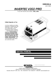
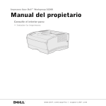
INPUT RECONNECT PROCEDURE
Return to Master TOC
INPUT LEADS
L1 & L2
On multiple input voltage welders, be sure the machine
is connected per the following instructions for the voltage being supplied to the welder.
CAUTION
LEAD H1
(DO NOT
REMOVE)
Failure to follow these instructions can cause immediate failure of components within the welder and void
machine’s warranty.
----------------------------------------------------------------------Multiple voltage models are shipped connected for the
highest voltage. To change this connection refer to the
following instructions.
Return to Section TOC
A-6
INSTALLATION
WARNING
FOR LOWEST RATED VOLTAGE
: H2 CONNECTED
FOR HIGHEST RATED VOLTAGE
: H3 CONNECTED
BACK VIEW OF LINE SWITCH
FIGURE A.1 Reconnect Leads
ELECTRIC SHOCK can kill.
• Turn the input power OFF at the disconnect switch or fuse box before
working on this equipment.
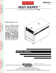
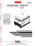
OUTPUT CONNECTIONS
-----------------------------------------------------------------------For the lowest rated voltage connection (Refer to figure A.1):
1. Remove the sheet metal left side cover.
ELECTRODE/GAS
OUTLET
RECEPTACLE
(TWIST-MATE)
Return to Master TOC
Return to Section TOC
2. Disconnect lead H3 from the power switch and insulate with the insulation from the H2 lead.
3. Connect lead H2 to the power switch where H3 was
connected.
4. Tighten connections.
WORK CABLE & CLAMP
5. Replace sheet metal cover and all screws
For the highest rated voltage connection (Refer to figure A.1):
The machine is normally shipped connected for the
highest rated voltage, however verify the following:
FIGURE A.2 Location of Output Connections
1. Remove the sheet metal left side cover.
Return to Master TOC
Return to Section TOC
2. Disconnect lead H2 from the power switch and insulate with the insulation from the H3 lead.
3. Connect lead H3 to the line switch where H2 was
connected.
4. Tighten connections.
CONNECTIONS FOR TIG (GTAW) WELDING
TIG TORCH CONNECTION
Refer to Included Equipment in the Operation Section
of this manual for TIG welding equipment which is
included with the PRECISION TIG 185.
5. Replace sheet metal cover and all screws.
PRECISION TIG 185
INSTALLATION
Return to Master TOC
Return to Section TOC
A-7
A PTA-17 Twist-Mate TIG welding torch with cable and
connector is supplied with the Ready-Pak Models and
available for other models (See Accessories Section).
Turn the Power Switch “OFF”. Connect the torch cable
Twist-Mate quick connect plug into the Electrode/Gas
Output Receptacle on the front of the welder and turn
it clockwise until it is tight. This is a Twist-Mate quick
connect terminal and also provides the gas connection
for the shielding gas to the torch.
WARNING
To avoid receiving a high frequency shock, keep
the TIG torch and cables in good condition.
------------------------------------------------------------------------
A-7
A cylinder is loaded by leaning it slightly sideways and
rocking it up on the platform, being careful not to allow
the Under-Storage Cart to roll. Secure the cylinder in
place with the provided chain. Unload by following
these steps in reverse.
REMOTE CONTROL CONNECTION
A remote control receptacle is provided on the case
front of the welder for connecting a remote control to to
the machine. A Foot Amptrol™, foot activated remote
control, is included with the PRECISION TIG 185
Ready-Pak models and available separately for other
models. Refer to the Optional Accessories section of
this manual for other available remote controls.
Return to Master TOC
Return to Master TOC
Return to Master TOC
Return to Section TOC
Return to Section TOC
Return to Section TOC
WORK CABLE CONNECTION
A work cable with attached work clamp is factory connected to the PRECISION TIG 185. To minimize high
frequency interference, refer to Machine Grounding
and High Frequency Interference Protection
section of this manual for the proper procedure on
grounding the work clamp and work piece.
SHIELDING GAS CONNECTION
An adjustable gas pressure regulator with flow gage
and hose is supplied with the PRECISION TIG 185
Ready-Pak Models and available separately for other
models (See Accessories Section). Obtain the necessary inert shielding gas (usually argon). Connect the
cylinder of gas with the pressure regulator and flow
gage. Install the gas hose between the regulator and
gas inlet (located on the rear of the welder). The gas
inlet has a 5/16-18 right hand female thread;
CGA#032.
CONNECTIONS
WELDING
FOR
STICK
(SMAW)
STICK ELECTRODE CABLE AND WORK
CABLE CONNECTION
Refer to Field Installed Options in Accessories Section
of this manual for STICK welding equipment which is
available for use with the PRECISION TIG 185. An
electrode holder with Twist-Mate cable and Twist-Mate
connector are available separately for use with the
PRECISION TIG 185. (See Accessories Section).
Turn the Power Switch “OFF”. Connect the Twist-Mate
quick connect plug into the Electrode/Gas Output
Receptacle and turn it clockwise until it is tight. The
work cable and work clamp are factory connected.
The available Under-Storage Cart features a low platform that simplifies loading and unloading of gas cylinders.
WARNING
CYLINDER could explode
if damaged.
• Keep cylinder upright and chained
to a support.
• Keep cylinder away from areas
where it could be damaged.
• Never allow the torch to touch the cylinder.
• Keep cylinder away from live electrical circuits.
• Maximum inlet pressure 150 psi.
------------------------------------------------------------------------
PRECISION TIG 185
Return to Section TOC
Return to Master TOC
Return to Section TOC
Return to Master TOC
Return to Master TOC
Return to Section TOC
Return to Master TOC
Return to Section TOC
A-8
NOTES
PRECISION TIG 185
A-8
Return to Master TOC
Section B-1
TABLE OF CONTENTS
- OPERATION SECTION -
Section B-1
Operation ................................................................................................................Section B
Safety Precautions .......................................................................................................B-2
Graphic Symbols..........................................................................................................B-2
Product Description......................................................................................................B-3
Recommended Processes and Equipment..................................................................B-3
Welding Capability (duty cycle) ....................................................................................B-3
Return to Master TOC
Controls and Settings...................................................................................................B-4
Control Functionality .............................................................................................B-4/B-5
Operating Steps ...........................................................................................................B-5
Welding in TIG Mode....................................................................................................B-5
Pulse TIG Control .........................................................................................................B-5
Remote Control Operation ...........................................................................................B-6
Benefits of the Precision TIG 185 Design ....................................................................B-6
Welding in Stick Mode .................................................................................................B-7
Return to Master TOC
Return to Master TOC
Recommended Electrode Amperage Ranges..............................................................B-7
PRECISION TIG 185
Return to Master TOC
Return to Master TOC
Return to Master TOC
Return to Master TOC
Return to Section TOC
Return to Section TOC
Return to Section TOC
Return to Section TOC
B-2
B-2
OPERATION
SAFETY PRECAUTIONS
GRAPHIC SYMBOLS THAT APPEAR ON
THIS MACHINE OR IN THIS MANUAL
Read and understand this entire section before operating the machine.
INPUT POWER
WARNING
ELECTRIC SHOCK
can kill.
• Do not touch electrically live parts
or electrode with skin or wet clothing.
• Insulate yourself from work and
ground.
• Always wear dry insulating gloves.
• Read and follow “Electric Shock Warnings” in the
Safety section if welding must be performed under
electrically hazardous conditions such as welding in
wet areas or on or in the workpiece.
-------------------------------------------------------------------------------FUMES AND GASES
can be dangerous.
• Keep your head out of fumes.
• Use ventilation or exhaust at the
arc, or both, to remove fumes and
gases from breathing zone and
general area.
-----------------------------------------------------------------------WELDING SPARKS can cause fire or
explosion
• Keep flammable material away.
• Do not weld on containers that
have held combustibles.
-----------------------------------------------------------------------ARC RAYS can burn.
• Wear eye, ear and body
protection.
-----------------------------------------------------------------------Observe additional Safety Guidelines detailed in
the beginning of this manual.
------------------------------------------------------------------------
PRECISION TIG 185
POSITIVE OUTPUT
NEGATIVE OUTPUT
DIRECT CURRENT
PROTECTIVE
GROUND
WARNING OR
CAUTION
DO NOT SWITCH
WHILE WELDING
Return to Master TOC
Return to Master TOC
Return to Master TOC
Return to Section TOC
Return to Section TOC
Return to Section TOC
B-3
PRODUCT DESCRIPTION
The Precision TIG 185 is a member of our field
acclaimed Precision TIG family of industrial arc weld ing power sources. Premium features include:
1. Precise constant current output.
2. Full range square wave AC/DC TIG (GTAW) weld-ing.
3. Enhanced version of the patented MicroStart™Technology for its lower Minimum(5 amps) to
higher Maximum (185 amps) output control range.
4. Built-in high frequency stabilization for DC TIG starting and continuous AC TIG welding.
5. AC/DC Stick (SMAW capability.) A new undercarriage (with gas bottle rack) is available for field
installation, or is included with an available ReadyPak TIG Welding Package. The Precision TIG
patented convenient built-in storage provisions for
welding components and cable management.
The Precision TIG 185 also provides advanced features such as:
• Digital Meter
• Presettable control, adjustable Auto Balance™
• Fan As Needed (F.A.N.)
• Timers for fixed Preflow and variable Postflow shielding gas.
• Built-in, easy to set single knob Pulse TIG control with
a "blinking" light to indicate the pulse frequency setting.
• Auto-Sense remote control selection.
• Tool-less Twist-Mate electrode cable connection.
• Built-in work clamp cable permanently attached.
Four models are available for 60Hz. with Domestic and
Canadian input voltages, as well as an International
model with 50/60Hz voltages.
RECOMMENDED PROCESSES AND
EQUIPMENT
Return to Master TOC
RECOMMENDED PROCESSES
Return to Section TOC
B-3
OPERATION
The Precision TIG 185 is recommended for the TIG
(GTAW) and Stick (SMAW) welding processes within
its output capacity range of 5 amps DC,or 7 amps AC,
to 185 amps AC/DC. It is compatible with most
Magnum TIG accessories, as well as many industry
standard items, such as TIG torches (adapted for
Twist-Mate), hoses, and water coolers.
PROCESS LIMITATIONS
The Precision TIG machines are not recommended for
arc gouging due to it's limited output capacity, and are
also not recommended for pipe thawing.
RECOMMENDED EQUIPMENT/INTERFACE
(See Installed Options in Accessories Section for
more details)
The Precision TIG 185 will be available as a basic
Machine (Only) and in two Factory-Configured Welding
Packages:
1. Machine(Only) (K2345-1)
2. Ready-Pak (K2347-1)
3. Ready-Pak w/Cart (K2347-2)
Basic module will also be available as with Domestic,
Canadian and International input voltages for user configuration, with optional accessories.
Select Machine
Torch Starter Kit
(Select one)
Water Cooler
Under-Storage
Cart (Optional )
Optional Remote
Trigger Device
(Select one)
208/230/1/60 Machine with 6 NEMA 6-50P
Plug Cable and Receptacle (K2345-1)
460/575/1/60 Machine only with cable (K2345-2)
380/400/415/1/50/60 Machine only
with cable (K2346-1)
Air Cooled System: Water Cooled System:
TIG-Mate
TIG-Mate 20
Torch Starter Kit*
Torch Starter Kit*
Not Applicable
115V 50/60Hz
Cool-Arc 40*
K2348-(*)
Arc Start Switch*
Foot Amptrol*
Start Pedal Foot Amptrol*
Hand Amptrol*
*For “Part Numbers” or “K Numbers” see Accessories Section.
EQUIPMENT LIMITATIONS
The Precision TIG machines are protected from over
loads beyond the output ratings and duty cycles, per
the Specifications in the Installation Section, with
Thermostat protection of the output power coils and
rectifiers.
The PRECISION TIG 185 machine uses Twist-Mate
output terminals, therefore stud connection adapters
(such as LECO. S19257-series) cannot be used for
torch connection.
If a Precision Tig 185 is powered from an engine generator which doesn’t have sufficient capacity, the AC
Balance control and the Output control will not provide
full range of control.
WELDING CAPABILITY(Duty Cycle)
The PRECISION TIG 185 is rated at 185 amps, 27
volts, at 15% duty cycle on a ten minute basis. It is
capable of higher duty cycles at lower output currents.
See rated output graph, on specification sheet located
in the Installation Section. If the duty cycle is exceeded, a thermal protector will shut off the output until the
machine cools.
PRECISION TIG 185
Return to Master TOC
Return to Section TOC
B-4
B-4
OPERATION
CONTROLS AND SETTINGS
All operator controls and adjustments are located on the front of the PRECISION TIG 185. Refer to Figure B.1
and corresponding explanations.
FIGURE B.1 - CONTROL PANEL
13
9
3
4
5
1. POWER SWITCH
2. POLARITY SWITCH
3. MODE SWITCH
4. AC BALANCE CONTROL
5. MAXIMUM OUTPUT CONTROL (AMPS)
6. DIGITAL METERS
7. POST FLOW TIME
8. PULSE TIG CONTROL
9. THERMAL SHUTDOWN LIGHT
10. REMOTE RECEPTACLE
11. ELECTRODE/GAS OUTPUT
RECEPTACLE
12. WORK CABLE
13. REMOVABLE LIFT EYEBOLT
6
Return to Master TOC
Return to Section TOC
8
7
1
2
11
10
12
CONTROL FUNCTIONALITY
Return to Master TOC
Return to Master TOC
Return to Section TOC
Return to Section TOC
1. POWER SWITCH – Input line switch turns input
power ON or OFF, as indicated by the on or off status of the front panel digital display (See Item 6).
2. POLARITY SWITCH – The rotary power switch has
3-positions for DC+, AC and DC- selections for the
electrode output stud welding polarity.
CAUTION
• Do not switch the polarity switch
while welding or damage may result
to the machine.
-----------------------------------------------------------------------3. MODE SWITCH – The push button switch allows
selection of the two machine welding modes as indicated by colored mode lights:
• STICK mode – Top position Red light.
• TIG mode – Bottom position Green light.
4. AC BALANCE CONTROL – The AC Balance
Control permits adjustment of the AC TIG wave balance adjustment from Max. Penetration (80% negative wave) at full CW rotation setting, to Max.
Cleaning (60% positive wave) at CCW rotation, and
includes:
• Auto Balance position indicated by the Green panel
light turning on.
This setting position feature automatically provides the
proper amount of cleaning and penetration for normal
AC TIG welding.
5. MAXIMUM OUTPUT CONTROL – Presets the output welding current over the rated output range of
the machine:
• With a Remote Current Control (Amptrol) connected to the Remote Receptacle (See item 10), this
knob sets the Maximum output current level set
table with the remote Amptrol.
• For Pulse TIG (See Item 8) this knob sets the Peak
Pulse level, with the Remote Amptrol (if used).
6. DIGITAL METER – A 3 digit LED meter is used to
display the preset output current level before welding, and actual output level while welding:
• A lit display indicates input power is turned on.
(See Item 1.)
7. POST FLOW TIME – Sets the TIG mode shielding
gas post flow time over the range of about 1 to 30
seconds after the arc is shut off.
Note: Gas preflow time is fixed at 0.5 second only in
TIG mode, but no preflow time will occur if the arc is
restarted during Post Flow time, since shielding gas
would not have stopped flowing.
PRECISION TIG 185
Return to Master TOC
Return to Master TOC
Return to Master TOC
Return to Master TOC
Return to Section TOC
Return to Section TOC
Return to Section TOC
Return to Section TOC
B-5
OPERATION
B-5
8. PULSE TIG CONTROL – The Pulse TIG feature
built into the Precision TIG 185 is simplified to be a
single knob control which sets the Pulse Frequency
over the peak pulses/sec. range of about 0.1 to 20
pulses per second:
• Full CCW (min.) setting of the control knob shuts
off Pulse TIG (0.0 pps).
• Peak Pulse level is set by the Max. Output Control
and the Remote Amptrol (if used).
• Background Current level is typically optimized at
a fixed 50% of Peak Pulse level setting.
• Peak Pulse % On-time is typically optimized at a
fixed50%.
A Green light "blinks" with each Peak Pulse to indicate the Pulse TIG Control setting before and during
welding.
OPERATING STEPS
9. OVER TEMPERATURE LIGHT If the welder
overheats due to blocked air flow, high ambient air
temperature, or exceeded duty cycle, an internal
thermostat will open disabling the welding output
and this yellow light will illuminate. The cooling fans
will continue to run to cool the unit during this time.
The light will go out when the unit cools and the
thermostat resets. Once the light goes out, the
machine will again become available to weld.
5. Turn on the cylinder gas valve and adjust the flow
regulator to obtain desired flow.
10. REMOTE RECEPTACLE – Provides for connection of remote control and/or arc start switch only in
TIG Mode: ( There is no remote output control
capability when stick welding.
• Plugging a remote current control (Amptrol) into
this receptacle automatically switches the output
control from the panel Max Output Control (See
Item 5) to the remote control.
• The connected remote control will then control the
output current between the Min. range of the
machine and the setting of the panel Max Output
Control.
• Switching Mode Switch (See Item 3) to Stick will
automatically disable the connected remote control and switch the output control back to the Max
Output panel control.
8. Depress the Foot Amptrol to energize the torch and
establish an an arc with the work piece. The digital
meter reads the actual amps while welding.
11. ELECTRODE/GAS OUTPUT RECEPTACLE This quick connect Twist-Mate receptacle provides
electrical connection to the electrode holder and
cable for Stick welding and a combined electrical
and gas connection for the TIG torch when TIG
welding.
Use this knob to set the frequency or the number of
pulses per second(pps), from 0.1pps to 20pps.
12. WORK CABLE - This work cable is factory connected to the welder and is connected to the work
piece to complete the welding circuit. Refer to
Machine Grounding and High Frequency
Interference Protection in the Installation section
of this manual for the proper procedure on grounding the work clamp and work piece to minimize
high frequency interference.
WELDING IN TIG MODE
1. Connect the TIG torch and cable Twist-Mate quick
connect plug to the Electrode/Gas output receptacle. This receptacle also contains an integral gas
connection for the torch. Connect the work clamp to
the work piece.
2. Set the TIG/STICK switch to “TIG”.
3. Set the Polarity Switch to DC- for welding steel or
stainless steel; or to AC for welding aluminum.
4. Connect the Foot Amptrol to the Remote Control
Connector.
6. Turn the power switch to “ON”. NOTE: There will be
a 15 second gas flow when the power is turned on.
7. Preset the Output Control on the control panel to the
maximum desired amps, as read on the digital
meter.
NOTE: When the TIG/STICK switch is set to “TIG”,
depressing the remote control will start a 0.5 second
gas pre-flow before energizing the TIG torch. When the
remote control is released the TIG torch is de-energized and gas flow will continue for the time set by the
Post Flow Time control. When the polarity switch is set
to DC, the TIG Arc Starter will turn on and off automatically to start and stabilize the arc. In AC the TIG Arc
Starter will turn on with the output and remain on continuously until the remote control is released.
PULSE TIG CONTROL
• This setting adjusts heat output and bead shape for
travel speed. Thinner plate that is welded with faster
travel speed will require higher frequency than thicker plate with slower travel speed. 2-3pps is a typical
starting point.
PRECISION TIG 185
Return to Master TOC
Return to Master TOC
Return to Master TOC
Return to Master TOC
Return to Section TOC
Return to Section TOC
Return to Section TOC
Return to Section TOC
B-6
OPERATION
B-6
REMOTE CONTROL OPERATION
BENEFITS OF THE PRECISION TIG 185 DESIGN
A Foot Amptrol ™is included with the PRECISION TIG
185 Ready-Pak models and availiable for other models
(See Accessories Section) for remote current control
while TIG welding. An optional Hand Amptrol may also
be used. An optional Arc Start Switch may be used to
start and stop the welding if no remote control of the
current is desired. Refer to the Accessories Section of
this manual.
In AC TIG welding of aluminum, the positive portion of
the AC wave provides cleaning (removal of aluminum
oxide) of the work piece. This is desirable on materials
with a heavy oxide coating. However the positive portion may also cause the electrode to overheat at high
currents causing “tungsten spitting”. The negative portion of the AC wave offers no cleaning action but concentrates more heat on the work.
Both the Hand and Foot Amptrol work in a similar manner. For simplicity, the following explanation will refer
only to “Amptrols”, meaning both Foot and Hand models. The term “minimum” refers to a foot pedal in the
“up” position, as it would be with no foot pressure, or a
Hand Amptrol in the relaxed position, with no thumb
pressure.
The AC waveform of the PRECISION TIG 185 optimizes cleaning and heating of the work. The result is
the capability to weld through the complete range in AC
TIG or DC- TIG requiring only one electrode, a 3/32”
2% thoriated tungsten.
“Maximum” refers to a fully depressed Foot Amptrol,or
a fully extended Hand Amptrol.
When the welder is in TIG modes activating the
Amptrol energizes the electrode terminal and varies
the output welding current from its minimum value of 5
Amp (DC) or 7 Amp (AC), to the maximum value set by
the Current Control on the control panel. This helps
eliminate accidental high current damage to the work
piece and/or tungsten, and provides a fine control of
the current. When the welder is in the stick mode a
remote control has no effect and is not used.
It is important to note that, in some cases, the tungsten
will not start an arc at the minimum current because
the tungsten may be too large or cold. To start an arc
reliably, it is important to depress the Amptrol far
enough so that the machine output current is near the
tungsten operating range. For example, a 3/32” tungsten may be used on DC- to weld over the full range of
the machine.
To start the arc, the operator may have to turn the current control up and depress the Amptrol approximately
1/4 of the way down. Depressing the Amptrol to its minimum position may not start the arc. Also if the current
control is set too low, the arc may not start. In most
cases, a large or cold tungsten will not readily establish
an arc at low currents. This is normal. In Direct Current
mode the PRECISION TIG 185 will start a 3/32”, 2%
thoriated tungsten electrode at 15 amperes provided
the electrode tip is properly grounded and not contaminated.
PRECISION TIG 185
Return to Master TOC
Return to Section TOC
B-7
B-7
OPERATION
WELDING IN STICK MODE
5. Turn the power switch to “ON”.
1. Put the electrode holder and cable quick connect
plug into the electrode output receptacle. Turn clockwise until tight. Connect the work clamp to the work
piece.
6. Adjust the Current Control to the desired amps.
2. Set the TIG/STICK switch to “STICK”.
3. Set the Polarity Switch to the weld mode desired for
the type of electrode being used (most commonly
DC+).
7. Strike an arc and weld.
NOTE: When the TIG/STICK switch is set to “STICK”
the output is always on when the power switch is on. A
remote control has no effect on the welding current and
the gas flow and high frequency TIG arc starter are disabled.
4. Place the electrode in the electrode holder.
Return to Master TOC
Return to Master TOC
Return to Section TOC
Return to Section TOC
WARNING
• In Stick Mode the output terminal
and electrode will be electrically hot
whenever the power switch is turned
on.
-----------------------------------------------------------------------
RECOMMENDED ELECTRODE AMPERAGE RANGES - PRECISION TIG 185
The PRECISION TIG 185 is rated from 5-185 Amps.
SMAW Process
Welding Amp Range for Stick Electrode Size
ELECTRODE TYPE
POLARITY
3/32"
1/8"
5/32"
Fleetweld 5P, Fleetweld 5P+ E6010
DC+
40 - 70
75 - 130
90 - 175
Fleetweld 180
E6011
DC+
40 - 80
55 - 110
105 - 135
Fleetweld 37
E6013
DC+
70 - 95
100 - 135
145 - 180
Fleetweld 47
E7014
DC75 - 95
100 - 145
135 - 200
Excalibur
E7018
DC+
85 - 110
110 - 160
130 - 200
Blue Max Stainless
DC+
40 - 80
75 - 110
95 - 150
Red Baron Stainless
DC+
40 - 70
60 - 100
90 - 140
Mild steel procedures are based on recommended procedures listed in C2.10 8/94 and the maximum rating of the PRECISION TIG 185
Blue Max procedures are based on C6.1 6/95
Red Baron Procedure are based on ES-503 10/93
Electrode Polarity
Electrode Tip Preparation
Return to Master TOC
Return to Section TOC
Electrode Type
Tungsten Size (in.)
.010
.020
.040
1/16
3/32
1/8
DCSharpened
EWTh-1, EWCe-2
EWTh-2, EWLa-1
EWG
Up to 15 A.
Up to 15 A.
Up to 80 A.
Up to 150 A.
Up to MAX. A.
X
GTAW Process
AC
Balled
EWZr
EWTh-1, EWTh-2
EWP
EWCe-2, EWLa-1
EWG
Up to 10 A.
Up to 15 A.
Up to 15 A.
Up to 20 A.
Up to 40 A.
Up to 60 A.
Up to 100 A.
Up to 130 A.
Up to 160 A.
Up to MAX. A.
Up to MAX. A.
X
Approximate Argon
Gas Flow Rate
C.F.H. (l/min.)
Aluminum
3-8
(2-4)
5-10
(3-5)
5-10
(3-5)
5-10
(3-5)
13-17 (6-8)
15-23 (7-11)
Tungsten electrodes are classified as follows by the American Welding Society (AWS):
Pure ..................................EWP ........green
TRI-MIX OF ELEMENTS.............EWG.........gray
+1% Thoria .......................EWTh-1 ...yellow
+2% Thoria .......................EWTh-2 ...red
+2% Ceria.........................EWCe-2...orange
+1.5% Lanthana ...............EWLa-1 ...black
+0.15 to 0.40% Zirconia....EWZr .......brown
Ceriated Tungsten is now widely accepted as a substitute for 2% Thoriated Tungsten in AC and DC applications.
PRECISION TIG 185
Stainless
Steel
3-8
(2-4)
5-10 (3-5)
5-10 (3-5)
9-13 (4-6)
11-15 (5-7)
11-15 (5-7)
Return to Section TOC
Return to Master TOC
Return to Section TOC
Return to Master TOC
Return to Master TOC
Return to Section TOC
Return to Master TOC
Return to Section TOC
B-8
NOTES
PRECISION TIG 185
B-8
TABLE OF CONTENTS
- ACCESSORIES SECTION -
Options / Accessories ...........................................................................................C-2/C-3
Return to Master TOC
Return to Master TOC
Section C-1
Accessories ............................................................................................................Section C
Return to Master TOC
Return to Master TOC
Section C-1
PRECISION TIG 185
Return to Master TOC
Return to Master TOC
Return to Section TOC
Return to Section TOC
C-2
C-2
ACCESSORIES
FACTORY INSTALLED OPTIONS
2. Precision TIG 185 Ready-Pak w/Cart (K2347-2)
The Precision TIG 185 will be available in two FactoryConfigured Welding Packages:
•
•
•
•
•
•
1. Precision TIG 185 Ready-Pak (K2347-1)
•
•
•
•
•
•
208/230/1/60 Machine (K2345-1)
9 ft. (2.7m) Input Cable with NEMA 6-50P Plug*
NEMA 6-50R Receptacle
Integrated 10 ft.(3.1m)Work Lead w/Clamp*
Gas Regulator with 10 ft.(3.1m). Hose
PTA-17 12.5”(318mm) Ultra=Flex Torch with
3/32”(2.4mm)Electrode and Parts
• Foot Amptrol (K870)
• TIG Slide Rule ( WC332)*
• GTAW Book (JFLF-834)*
• Lift Eyebolt*
208/230/1/60 Machine (K2345-1)
9 ft.(2.7m) Input Cable with NEMA 6-50P Plug*
NEMA 6-50R Receptacle
Integrated 10 ft.(3.1m) Work Lead w/Clamp*
Gas Regulator with 10 ft.(3.1m) Hose
PTA-17 12.5 ft.(3.8m) One cable Superflex Torch with
3/32”(2.4mm) Electrode and Parts
• Foot Amptrol (K870)
• TIG Slide Rule (WC332)*
• GTAW Book (JFLF-834)*
• Lift Eyebolt*
• Under-Storage Cart (K2348-1)
* Included with K2345-1 Machine Only model.
The Precision TIG 185 will also be available as Basic
models with Domestic input voltages for user-configuration with optional accessories: (See Table C.1)
TABLE C.1
Select Machine
208/230/1/60 Machine with 9 ft.(2.7m) NEMA 6-50P Plug Cable and Receptacle (K2345-1)
460/575/1/60 Machine only with Cable (K2345-2)
380/400-415/1/50-60 Machine only with Cable (K2346-1)
Return to Master TOC
Return to Section TOC
Optional
Torch Starter Kit
(Select one)
Water Cooler
Optional UnderStorage Cart
Return to Master TOC
Return to Section TOC
Optional Remote
Trigger Device
(Select one)
Water Cooled System
Air Cooled System
K2267-1 TIG-Mate 20 Torch Starter Kit
Includes:
• 200A PTW-20 12.5 ft.(3.81m) Torch
• KP510 Parts Kit
• Regulator & Hose
• K1622-4 Twist Mate Torch Adapter
• Water Hose & Hose Coupler
• Work Cable & Clamp (Not required for
Precision TIG 185)
K2266-1 TIG-Mate Torch Starter
Kit Includes:
• 150A PTA-17 12.5 ft.(3.81m) Torch.
• KP508 Parts Kit.
• Regulator & Hose.
• K1622-1 Twist Mate Torch Adapter.
• Work Cable & Clamp (Not required for Precision
TIG 185)
Not Applicable
K1813-1 115V 50/60Hz Cool-Arc 40
K2348-1
K814 Arc Start Switch
K870 Foot Amptrol
K870-1 Start Pedal Foot Amptrol
K963-3 Hand Amptrol
PRECISION TIG 185
Return to Master TOC
Return to Section TOC
C-3
ACCESSORIES
FIELD INSTALLED OPTIONS
The following Options/Accessories are available for the
Precision TIG 185:
• K2348-1 Under-Storage Cart
Includes a front magnetic latch storage drawer and
rear storage bin on a single bottle undercarriage.
(L12225 Installation Instructions included)
Return to Master TOC
Return to Section TOC
• K870 Foot Amptrol
Single pedal foot activation of arc start switch and
output control, with 25 ft.(7.6m) plug cable.
• Magnum “Pro-Torch™ TIG Torch” assemblies and
Accessories.
Requires Twist-Mate Adapter:
K1622-1 for PTA-9/-17
K1622-3 for PTA-26
K1622-4 for PTW water cooled torch
• Harris #3100211 Harris Argon Flow Regulator
(Includes 10 ft.(3.1m) hose.)
• K2374-1 Electrode Holder and Cable
200 amp Electrode Holder with 10 ft.(3.1m) cable
and Twist-Mate connector.
• K870-1 Start Pedal Foot Amptrol
Independent start pedal on control pedal provides
two-stage foot action to easily feel start switch closure at minimum output level for enhanced arc start
and crater-fill control. Provided with adjustable, or
removable , heel stop and 25 ft.(7.6m) plug cable.
• K963-3 Hand Amptrol
Fastens to torch for convenient thumb activation of
arc start switch and output control, with 25 ft.(7.6m)
plug cable:
Return to Master TOC
Return to Master TOC
Return to Section TOC
• K814 Arc Start Switch
Needed for TIG welding without an Amptrol. Includes
25 ft.(7.6m) plug cable, and attaches to torch for
convenient finger control.
Return to Section TOC
C-3
• TIG-Mate Torch Starter Kits:
Includes Torch with Twist-Mate adapter and accessories listed below:
K2266-1 TIG-Mate Torch Starter Kit Includes:
• 150A PTA-17 12.5 ft.(3.8m) Torch
• KP508 Parts Kit
• Regulator & Hose
• K1622-1 Twist Mate Torch Adapter
• Work Cable & Clamp (Not required for Precision
TIG 185)
K2267-1 TIG-Mate 20 Torch Starter Kit Includes:
• 200A PTW-20 12.5 ft.(3.8m) Torch
• KP510 Parts Kit
• Regulator & Hose
• K1622-4 Twist Mate Torch Adapter
• Water Hose & Hose Coupler
• Work Cable & Clamp
(Not required for Precision TIG 185)
PRECISION TIG 185
Return to Section TOC
Return to Master TOC
Return to Section TOC
Return to Master TOC
Return to Master TOC
Return to Section TOC
Return to Master TOC
Return to Section TOC
C-4
NOTES
PRECISION TIG 185
C-4
Return to Master TOC
Section D-1
TABLE OF CONTENTS
- MAINTENANCE SECTION -
Section D-1
Maintenance ...........................................................................................................Section D
Safety Precautions ........................................................................................................D-2
Routine Maintenance.....................................................................................................D-2
Periodic Maintenance....................................................................................................D-2
Spark Gap Adjustment ..................................................................................................D-2
Fan Motor and Blade Replacement ..............................................................................D-2
Return to Master TOC
Return to Master TOC
Return to Master TOC
Major Component Locations.........................................................................................D-3
PRECISION TIG 185
Return to Master TOC
Return to Section TOC
D-2
WARNING
SAFETY PRECAUTIONS
WARNING
ELECTRIC SHOCK can kill.
• Only qualified personnel should perform this maintenance.
• Turn the input power OFF at the disconnect switch or fuse box before
working on this equipment.
Return to Master TOC
Return to Section TOC
• Do not touch electrically hot parts.
------------------------------------------------------------------------
WARNING
To avoid receiving a high frequency shock, keep
the TIG torch and cables in good condition.
------------------------------------------------------------------------
ROUTINE AND PERIODIC MAINTENANCE
Return to Master TOC
1. Disconnect power supply lines to machine before
performing periodic maintenance.
Return to Section TOC
D-2
MAINTENANCE
2. Periodically clean the inside of the machine with a
low pressure air system. Be sure to clean the following components thoroughly.
• Main Transformer
• Electrode/Gas Output Receptacle
• Polarity Switch
• Rectifier Assembly
• Arc Starter/Spark Gap Assembly
• PC Boards
• Fan Blades
Use extreme caution when working with circuit of
the high frequency. The high voltages developed
can be lethal. Turn the input power off using the
disconnect switch or fuse box before working
inside machine. This is particularly important when
working on the secondary circuit of the high voltage transformer (T3) because the output voltage is
dangerously high.
----------------------------------------------------------------------Refer to figure D.1. Note in highly dirty environments
where there is an abundance of conductive contaminants, use a low pressure air stream or a firm piece of
paper to clean the spark gap. Do not disturb the factory setting.
To check the spark gap:
- Turn off input power as specified above.
- Remove the right side panel from the
machine, the spark gap box is located on the
lower right side.
- Check the spark gap with a feeler gauge.
If adjustment is needed:
- Adjust the gap by loosening the allen head
screw in one of the aluminum blocks, near
the front of the unit and tighten the screw in
the new position.
If the gap is correct:
- Replace the wraparound.
8. Inspect gas hose and inlet fitting for cracks or leaks.
9. Replace any unreadable labels or decals.
10. Verify that the machine and welding circuit is properly grounded.
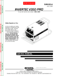
FIGURE D.1 SPARK GAP
3. Inspect welder output and control cables for fraying,
cuts, and bare spots.
.020 Spark Gap
4. Keep TIG torch and cables in good condition.
5. Clean air louvers to ensure proper air flow and cooling.
Return to Master TOC
Return to Section TOC
FAN MOTOR OR FAN BLADE REPLACEMENT
6. The fan motor has sealed ball bearings which
require no maintenance.
When installing a new fan blade or fan motor be sure
to maintain proper shaft spacing per Figure D.2 below.
7. SPARK GAP ADJUSTMENT
The spark gap is set at the factory to a gap of 0.020
See Figure D.1. This setting is adequate for most
applications. Where less high frequency is desired,
the setting can be reduced to 0.015 inches (0.4mm).
.30
FIGURE D.2
PRECISION TIG 185
Return to Master TOC
Return to Section TOC
D-3
D-3
MAINTENANCE
FIGURE D.2 — LOCATION OF MAINTENANCE COMPONENTS.
1. Case Front Assembly
2. Case Back Assembly
3. Arc Starter & Bypass Assembly
4. Center Assembly
5. Cover Assembly
6. Cart Base Assembly
7. Upper Cylinder Support Assembly
8. TIG Torch & Cable Assembly
9. Foot Amptrol Assembly (Pedal)
7
Return to Master TOC
Return to Section TOC
5
2
4
Return to Master TOC
Return to Section TOC
1
9
Return to Master TOC
Return to Section TOC
3
6
8
PRECISION TIG 185
Return to Section TOC
Return to Master TOC
Return to Section TOC
Return to Master TOC
Return to Master TOC
Return to Section TOC
Return to Master TOC
Return to Section TOC
D-4
NOTES
X
D-4
Return to Master TOC
Section E-1
TABLE OF CONTENTS
- THEORY OF OPERATION SECTION -
Section E-1
Theory of Operation ...............................................................................................Section E
General Description ......................................................................................................E-2
Input Power Circuit .......................................................................................................E-2
Output Rectification and Feedback Control.................................................................E-3
High Voltage/High Frequency Circuit ...........................................................................E-4
DC Welding Output.......................................................................................................E-5
AC Welding Output .......................................................................................................E-6
Return to Master TOC
SCR Operation..............................................................................................................E-7
Protective Circuits.........................................................................................................E-8
Thermal Protection .......................................................................................................E-8
Overload Protection ......................................................................................................E-8
FIGURE E.1 – PRECISION TIG 185 BLOCK LOGIC DIAGRAM
BY-PASS
BOARD
WORK
POLARITY
SWITCH
ELECTRODE
MAIN
TRANSFORMER
Return to Master TOC
INPUT
POWER
SWITCH
HI-FREQUENCY
TRANSFORMER
BYPASS
ASBLY
H1
H2
C
H
O
K
E
AC
DC+
SCR
BRIDGE
X1
HIGH VOLTAGE
TRANSFORMER
CIRCUIT
SHUNT
X2
AC
H3
DCF
E
E
D
B
A
C
K
115VAC
18VAC
CONTROL
BOARD
18VAC
115VAC
FAN
POWER
"ON"
DIGITAL
DISPLAY
MODE
SWITCH
Return to Master TOC
REMOTE
RECEPTACLE
THERMAL
LIGHT
GAS
VALVE
THERMOSTATS
OUTPUT
CONTROL
AC
POSTFLOW
PULSE
BALANCE CONTROL CONTROL
CONTROL
AUTO
PULSE TIG STICK
BALANCE FREQ. LED LED
LED
LED
X
Return to Master TOC
Return to Section TOC
E-2
E-2
THEORY OF OPERATION
GENERAL DESCRIPTION
3. Enhanced version of the patented MicroStartTM
Technology for its lower Minimum (5amps) to high-
The PRECISION TIG 185 is a member of our field
acclaimed Precision TIG family of industrial arc welding power sources. Premium features include:
er Maximum (185 amps) output control range.
4. Built-in high frequency stabilization for DC TIG
starting and continuous AC TIG welding.
1. Precise constant current output.
2. Full range square wave AC/DC TIG (GTAW) welding.
5. AC/DC Stick (SMAW capability.)
FIGURE E.2 Main Transformer and Input Power
BY-PASS
BOARD
WORK
POLARITY
SWITCH
ELECTRODE
Return to Master TOC
Return to Section TOC
MAIN
TRANSFORMER
INPUT
POWER
SWITCH
HI-FREQUENCY
TRANSFORMER
BYPASS
ASBLY
H1
H2
C
H
O
K
E
AC
DC+
SCR
BRIDGE
X1
HIGH VOLTAGE
TRANSFORMER
CIRCUIT
SHUNT
X2
AC
H3
DCF
E
E
D
B
A
C
K
115VAC
18VAC
CONTROL
BOARD
18VAC
115VAC
FAN
POWER
"ON"
DIGITAL
DISPLAY
Return to Master TOC
REMOTE
RECEPTACLE
Return to Master TOC
Return to Section TOC
Return to Section TOC
MODE
SWITCH
THERMAL
LIGHT
GAS
VALVE
THERMOSTATS
AC
POSTFLOW
PULSE
BALANCE CONTROL CONTROL
CONTROL
AUTO
PULSE TIG STICK
BALANCE FREQ. LED LED
LED
LED
INPUT POWER CIRCUIT
The desired single-phase input power is connected to
the TIG 185 through an input power switch located in
the front panel of the machine. The machine can be
configured for either 230VAC or 208VAC input voltage
by connecting the appropriate lead (H2 or H3) to the
input power switch. When the input power switch is
turned “ON” the input voltage is applied directly to the
primary of the main transformer.
OUTPUT
CONTROL
incorporated in the main transformer. The 115VAC
winding supplies power to the fan motor and also,
through the control board, powers the gas solenoid
valve and the high voltage transformer. The 18VAC
winding provides power to the trigger circuitry. The
other 18VAC winding is rectified and regulated to a
15VDC supply which operates the circuitry on the control board.
The main transformer changes the high voltage, low
current input power to a low voltage, high current output which is available at the main secondary winding
(X1 and X2). In addition three auxiliary windings are
NOTE: Unshaded areas of block logic diagrams are the subject of discussion.
PRECISION TIG 185
Return to Master TOC
Return to Section TOC
E-3
E-3
THEORY OF OPERATION
FIGURE E.3 Control Board and Output Feedback Control.
BY-PASS
BOARD
WORK
POLARITY
SWITCH
ELECTRODE
MAIN
TRANSFORMER
INPUT
POWER
SWITCH
HI-FREQUENCY
TRANSFORMER
BYPASS
ASBLY
H1
H2
C
H
O
K
E
AC
DC+
SCR
BRIDGE
X1
HIGH VOLTAGE
TRANSFORMER
CIRCUIT
SHUNT
X2
AC
H3
DCF
E
E
D
B
A
C
K
115VAC
Return to Master TOC
Return to Section TOC
18VAC
CONTROL
BOARD
18VAC
115VAC
FAN
MODE
SWITCH
REMOTE
RECEPTACLE
THERMAL
LIGHT
GAS
VALVE
THERMOSTATS
Return to Section TOC
Return to Master TOC
Return to Master TOC
AUTO
PULSE TIG STICK
BALANCE FREQ. LED LED
LED
LED
Return to Section TOC
POWER
"ON"
DIGITAL
DISPLAY
OUTPUT RECTIFICATION
FEEDBACK CONTROL
OUTPUT
CONTROL
AC
POSTFLOW
PULSE
BALANCE CONTROL CONTROL
CONTROL
AND
The AC output from the main transformer secondary is
rectified and controlled through the SCR bridge.
Output current is sensed at the shunt as a low voltage
signal and fed back to the control board. The control
board compares the commands of the mode switch,
output control, AC balance control, pulse control, postflow control, or remote control with the feedback information. The appropriate SCR gate firing signals are
created by the control board and sent to the SCR
bridge. The control board controls the firing of the
SCRs, which control the output of the machine. See
SCR Operation. The control board monitors the thermostats, and also controls the gas solenoid valve, thermal light, auto balance LED, pulse frequency LED, TIG
LED, stick LED, and the digital display.
NOTE: Unshaded areas of block logic diagrams are the subject of discussion.
PRECISION TIG 185
Return to Master TOC
Return to Section TOC
E-4
FIGURE E.4 High Voltage/High Frequency Circuit.
BY-PASS
BOARD
POLARITY
SWITCH
MAIN
TRANSFORMER
INPUT
POWER
SWITCH
HI-FREQUENCY
TRANSFORMER
BYPASS
ASBLY
H1
Return to Master TOC
Return to Section TOC
AC
Return to Master TOC
DCF
E
E
D
B
A
C
K
115VAC
18VAC
CONTROL
BOARD
18VAC
115VAC
FAN
POWER
"ON"
DIGITAL
DISPLAY
MODE
SWITCH
REMOTE
RECEPTACLE
Return to Master TOC
HIGH VOLTAGE
TRANSFORMER
CIRCUIT
SHUNT
X2
H3
Return to Section TOC
C
H
O
K
E
AC
DC+
SCR
BRIDGE
X1
H2
Return to Section TOC
E-4
THEORY OF OPERATION
THERMAL
LIGHT
GAS
VALVE
THERMOSTATS
OUTPUT
CONTROL
HIGH VOLTAGE / HIGH
FREQUENCY CIRCUIT
The control board passes the 115VAC voltage to the
primary of the high voltage transformer. The secondary of the high voltage transformer is coupled to a
spark gap generator and also to the high frequency
transformer. The high frequency transformer transfers
the high frequency “spark” to the electrode terminal
which is coupled to the TIG torch.
NOTE: Unshaded areas of block logic diagrams are the subject of discussion.
PRECISION TIG 185
Return to Section TOC
Return to Master TOC
Return to Section TOC
Return to Master TOC
E-5
E-5
THEORY OF OPERATION
DC WELDING OUTPUT
When the polarity switch is placed in either DC position, the AC voltage from the main transformer secondary is
applied to the SCR bridge. The SCR bridge and choke circuits are connected in a conventional full wave bridge
and filter configuration, resulting in a controlled DC output. Since the choke is in series with the negative leg of
the bridge and also in series with the welding load, a filtered DC is applied to the machine output terminals.
CHOKE
ELECTRODE
G
G
DC
PRIMARY
1Ø
G
G
Return to Section TOC
Return to Master TOC
Return to Section TOC
Return to Master TOC
WORK
FIGURE E.5 DC Welding Current Generation.
PRECISION TIG 185
Return to Section TOC
Return to Master TOC
Return to Section TOC
Return to Master TOC
E-6
E-6
THEORY OF OPERATION
AC WELDING OUTPUT
Rotating the polarity switch to the AC position changes the welding power circuit. One lead (X1) of the main
transformer secondary is connected to the machine output work terminal. The other secondary lead (X2) is
connected to one of the AC connections on the SCR bridge. The electrode terminal is connected to the other
AC side of the bridge. The choke is now electrically across the negative and positive SCR bridge connections.
With the ability of the choke to store energy and the SCRs to turn on at the appropriate times, an AC square
wave is developed and applied to the output terminals.
G
CHOKE
G
ELECTRODE
G
G
AC
DC
PRIMARY
1Ø
WORK
Return to Section TOC
Return to Master TOC
Return to Section TOC
Return to Master TOC
FIGURE E.6 AC Square Wave Welding Current Generation.
PRECISION TIG 185
Return to Section TOC
Return to Master TOC
Return to Section TOC
Return to Master TOC
Return to Section TOC
Return to Master TOC
E-7
THEORY OF OPERATION
SCR OPERATION
A silicon controlled rectifier (SCR) is a three terminal
device used to control rather large currents to a load.
An SCR acts very much like a switch. When a gate
signal is applied to the SCR it is turned ON and there
is current flow from anode to cathode. In the ON state
the SCR acts like a closed switch. When the SCR is
turned OFF there is no current flow from anode to
cathode thus the device acts like an open switch. As
the name suggests, the SCR is a rectifier, so it passes current only during positive half cycles of the AC
supply. The positive half cycle is the portion of the
sine wave in which the anode of the SCR is more
positive than the cathode.
between gate and cathode, the voltage between these
terminals must be slightly greater than 0.6V. Once the
SCR has fired it is not necessary to continue the flow
of gate current. As long as current continues to flow
from anode to cathode the SCR will remain on. When
the anode to cathode current drops below a minimum
value, called holding current, the SCR will shut off.
This normally occurs as the AC supply voltage passes
through zero into the negative portion of the sine wave.
If the SCR is turned on early in the positive half cycle,
the conduction time is longer resulting in greater SCR
output. If the gate firing occurs later in the cycle the
conduction time is less resulting in lower SCR output.
When an AC supply voltage is applied to the SCR, the
device spends a certain portion of the AC cycle time in
the on state and the remainder of the time in the off
state. The amount of time spent in the ON state is controlled by the Gate.
An SCR is fired by a short burst of current into the gate.
This gate pulse must be more positive than the cathode voltage. Since there is a standard PN junction
INPUT
CATHODE
OUTPUT
NOTE: AS THE GATE
PULSE IS APPLIED
LATER IN THE CYCLE
THE SCR OUTPUT
IS DECREASED.
ANODE
GATE
Return to Master TOC
GATE
Return to Section TOC
E-7
FIGURE E.7 SCR Operation
PRECISION TIG 185
Return to Master TOC
Return to Section TOC
E-8
THEORY OF OPERATION
PROTECTIVE CIRCUITS
Protective circuits are designed into the PRECISION
TIG 185 to sense trouble and shut down the machine
before the trouble damages the internal machine components. Both thermal protection and current overload
are included. Fan as needed (F.A.N.) Fan runs for 5
seconds at power-up and stops at idle 8 minutes after
welding.
Return to Master TOC
Return to Master TOC
Return to Master TOC
Return to Section TOC
Return to Section TOC
Return to Section TOC
THERMAL PROTECTION
E-8
by excessive output or duty cycle and the fan is operating normally, the power may be left on, and the reset
should occur within a 15 minute period. If the fan is not
functioning properly or the air intake louvers are
obstructed, then the input power must be removed and
the fan problem or air obstruction corrected.
OVERLOAD PROTECTION
The machine is electronically protected from producing
excessively high output currents. The output is limited
to 200 amps.
9. OVER TEMPERATURE LIGHTIf the welder
overheats due to blocked air flow, high ambient air
temperature, or exceeded duty cycle, an internal thermostat will open disabling the welding output and this
yellow light will illuminate. The cooling fans will continue to run to cool the unit during this time. The light will
go out when the unit cools and the thermostat resets.
Once the light goes out, the machine will again
become available to weld.
Once the machine cools sufficiently the thermostats
are self-resetting. If the thermostat shutdown is caused
PRECISION TIG 185
Return to Master TOC
Section F-1
TABLE OF CONTENTS
- TROUBLESHOOTING & REPAIR SECTION -
Section F-1
Troubleshooting & Repair Section ........................................................................Section F
How to Use Troubleshooting Guide..............................................................................F-2
PC Board Troubleshooting Procedures and Replacement...........................................F-3
Troubleshooting Guide ..................................................................................................F-4
Test Procedures
High Frequency Circuit Disable Procedure ..........................................................F-15
Return to Master TOC
T1 Transformer Test ..............................................................................................F-17
Static SCR Test ....................................................................................................F-21
Active SCR Test....................................................................................................F-25
Oscilloscope Waveforms
Normal Open Circuit Voltage Waveform-AC TIG Mode .......................................F-29
Normal Open Circuit Voltage Waveform-DC TIG Mode.......................................F-30
Normal Open Circuit Voltage Waveform-AC Stick Mode.....................................F-31
Normal Open Circuit Voltage Waveform-DC Stick Mode ....................................F-32
Typical Output Voltage Waveform-Machine Loaded AC TIG Mode.....................F-33
Typical Output Voltage Waveform-Machine Loaded DC TIG Mode ....................F-34
Typical Output Voltage Waveform-Machine Loaded AC Stick Mode ..................F-35
Return to Master TOC
Typical Output Voltage Waveform-Machine Loaded DC Stick Mode ..................F-36
Abnormal Open Circuit Voltage-DC TIG Mode One SCR not Functioning..........F-37
Replacement Procedures
SCR Bridge Assembly Removal and Replacement .............................................F-39
Polarity Switch Removal and Replacement .........................................................F-45
High Voltage Transformer Removal and Replacement ........................................F-49
Main Transformer and Output Choke Removal and Replacement ......................F-53
Return to Master TOC
Retest after Repair ......................................................................................................F-57
PRECISION TIG 185
Return to Master TOC
Return to Master TOC
Return to Master TOC
Return to Section TOC
Return to Section TOC
Return to Section TOC
F-2
TROUBLESHOOTING & REPAIR
F-2
CAUTION
This Troubleshooting Guide is provided to help
you locate and repair possible machine
malfunctions. Simply follow the three-step
procedure listed below.
Step 1. LOCATE PROBLEM (SYMPTOM). Look
under the column labeled “PROBLEM
(SYMPTOMS)”. This column describes possible
symptoms that the machine may exhibit. Find
the listing that best describes the symptom that
the machine is exhibiting. Symptoms are
grouped into three main categories: Feeding
Problems and Welding Problems.
Step 2. PERFORM EXTERNAL TESTS. The
second column, labeled “POSSIBLE AREAS OF
MISADJUSTMENT(S)”, lists the obvious external
possibilities that may contribute to the machine
symptom. Perform these tests/checks in the
order listed. In general, these tests can be
conducted without removing the case
wrap-around cover.
Step 3. PERFORM COMPONENT TESTS. The
last column, labeled “Recommended Course of
Action” lists the most likely components that may
have failed in your machine. It also specifies the
appropriate test procedure to verify that the
subject component is either good or bad. If there
are a number of possible components, check the
components in the order listed to eliminate one
possibility at a time until you locate the cause of
your problem.
All of the referenced test procedures referred to in
the Troubleshooting Guide are described in detail
at the end of this chapter. Refer to the
Troubleshooting and Repair Table of Contents to
locate each specific Test Procedure. All of the
referred to test points, components, terminal
strips, etc., can be found on the referenced
electrical wiring diagrams and schematics. Refer
to the Electrical Diagrams Section Table of
Contents to locate the appropriate diagram.
WARNING
Return to Master TOC
Return to Section TOC
HIGH VOLTAGE / HIGH FREQUENCY can damage test equipment.
• Perform all voltage and waveform checks with high frequency circuit OFF. Perform High
Frequency Disable Procedure.
CAUTION
If for any reason you do not understand the test procedures or are unable to perform the test/repairs safely, contact the Lincoln Electric Service Department for electrical troubleshooting assistance before you proceed. Call
1-888-935-3877.
PRECISION TIG 185
Return to Master TOC
Return to Section TOC
F-3
TROUBLESHOOTING & REPAIR
PC BOARD TROUBLESHOOTING PROCEDURES
WARNING
ELECTRIC SHOCK
can kill.
• Have an electrician install and
service this equipment. Turn the
input power OFF at the fuse box
before working on equipment. Do
not touch electrically hot parts.
Return to Master TOC
Return to Master TOC
Return to Master TOC
Return to Section TOC
Return to Section TOC
CAUTION
Return to Section TOC
F-3
Sometimes machine failures appear to be due to PC
board failures. These problems can sometimes be
traced to poor electrical connections. To avoid problems when troubleshooting and replacing PC boards,
please use the following procedure:
1. Determine to the best of your technical ability
that the PC board is the most likely component
causing the failure symptom.
2. Check for loose connections at the PC board
to assure that the PC board is properly
connected.
3. If the problem persists, replace the suspect PC
board using standard practices to avoid static
electrical damage and electrical shock. Read
the warning inside the static resistant bag and
perform the following procedures:
PC board can be damaged by static electricity.
- Remove your body’s static
charge before opening the staticshielding bag. Wear an anti-static
wrist strap. For safety, use a 1
Meg ohm resistive cord connected
to a grounded part of the
ATTENTION
Static-Sensitive equipment frame.
Devices
- If you don’t have a wrist strap,
Handle only at touch an un-painted, grounded,
Static-Safe
part of the equipment frame. Keep
Workstations
touching the frame to prevent
- Remove the PC board from the static-shielding bag
and place it directly into the equipment. Don’t set the
PC board on or near paper, plastic or cloth which
could have a static charge. If the PC board can’t be
installed immediately, put it back in the static-shielding bag.
- If the PC board uses protective shorting jumpers,
don’t remove them until installation is complete.
- If you return a PC board to The Lincoln Electric
Company for credit, it must be in the static-shielding
bag. This will prevent further damage and allow proper failure analysis.
4. Test the machine to determine if the failure
symptom has been corrected by the
replacement PC board.
NOTE: It is desirable to have a spare (known good)
PC board available for PC board troubleshooting.
NOTE: Allow the machine to heat up so that all
electrical components can reach their operating
temperature.
5. Remove the replacement PC board and
substitute it with the original PC board to
recreate the original problem.
a. If the original problem does not reappear by
substituting the original board, then the PC
board was not the problem. Continue to look
for bad connections in the control wiring
harness, junction blocks, and terminal strips.
b. If the original problem is recreated by the
substitution of the original board, then the PC
board was the problem. Reinstall the
replacement PC board and test the machine.
6. Always indicate that this procedure was
followed when warranty reports are to be
submitted.
NOTE: Following this procedure and writing on the
warranty report, “INSTALLED AND SWITCHED PC
BOARDS TO VERIFY PROBLEM,” will help avoid
denial of legitimate PC board warranty claims.
static build-up. Be sure not to
touch any electrically live parts at
the same time.
- Tools which come in contact with the PC board must
be either conductive, anti-static or static-dissipative.
PRECISION TIG 185
Return to Master TOC
Return to Master TOC
Return to Section TOC
Return to Section TOC
F-4
TROUBLESHOOTING & REPAIR
TROUBLESHOOTING GUIDE
PROBLEMS
(SYMPTOMS)
F-4
Observe Safety Guidelines
detailed in the beginning of this manual.
POSSIBLE AREAS OF
MISADJUSTMENT(S)
RECOMMENDED
COURSE OF ACTION
OUTPUT PROBLEMS
Machine is dead. No output - No
fan
1. Make sure that the input power 1. Check the input power switch
switch is in the "ON" position and
and associated wires for loose or
the machine is plugged in.
faulty connections.
2. Check the input voltage at the
2. Perform the T1 Transformer
machine. Input voltage must
Test.
match the rating plate and voltage connection. Refer to
Reconnect Procedure in the
Installation section of this manual.
3. Blown or missing fuses in the
input line.
The fan runs normally. No output
from the machine in either Stick or
TIG modes.
1. Check for proper input voltages
per nameplate and voltage
reconnect configuration.
2. Check to make sure the polarity
switch is in the proper position
and functioning correctly.
1. Check for loose or faulty connections on the heavy current carrying leads. (polarity switch, output
choke output terminals etc.)
2. Perform the T1 Transformer
Test.
Return to Section TOC
Return to Master TOC
Return to Section TOC
Return to Master TOC
3. Perform the SCR Bridge Test.
4. Check current control R1 for
proper operation. Normal resistance is 10,000 ohms. Also
check associated leads for loose
or faulty connections.
5. The control board may be faulty.
Replace.
CAUTION
If for any reason you do not understand the test procedures or are unable to perform the test/repairs safely, contact the Lincoln Electric Service Department for electrical troubleshooting assistance before you proceed. Call
1-888-935-3877.
PRECISION TIG 185
Return to Section TOC
Return to Master TOC
Return to Section TOC
Return to Master TOC
F-5
TROUBLESHOOTING & REPAIR
TROUBLESHOOTING GUIDE
PROBLEMS
(SYMPTOMS)
F-5
Observe Safety Guidelines
detailed in the beginning of this manual.
POSSIBLE AREAS OF
MISADJUSTMENT(S)
RECOMMENDED
COURSE OF ACTION
OUTPUT PROBLEMS
Fan runs - No output from machine 1. The welding application may
1. One of the thermostats may be
in either Stick or TIG modes and the
have exceeded the recommendfaulty. Check or replace. See
yellow light on the control panel is
ed duty cycle. Allow the unit to
wiring diagram.
on.
run until the fan cools the unit
and the yellow light goes out.
2. Check for loose or faulty wires on
the thermostats and associated
2. The air louvers may be blocked.
circuitry. See wiring diagram.
Remove air obstruction and allow
unit to cool.
The machine does not respond (no 1. Make certain the machine is in
gas flow, no high frequency and no
the TIG mode.
open circuit voltage) when the arc
start switch or Amptrol is activated - 2. The Amptrol may be defective.
fan is working normally.
Check for continuity(zero ohms)
between pins "D" and "E" on
cable connector when the
Amptrol is depressed.
1. Check the continuity (zero ohms)
of the leads between the remote
receptacle and plug J5 on the
control board. See wiring diagram.
2. Perform the T1 Transformer
Test.
Return to Section TOC
Return to Master TOC
Return to Section TOC
Return to Master TOC
3. The control board may be faulty.
Replace.
CAUTION
If for any reason you do not understand the test procedures or are unable to perform the test/repairs safely, contact the Lincoln Electric Service Department for electrical troubleshooting assistance before you proceed. Call
1-888-935-3877.
PRECISION TIG 185
Return to Section TOC
Return to Master TOC
Return to Section TOC
Return to Master TOC
F-6
TROUBLESHOOTING & REPAIR
TROUBLESHOOTING GUIDE
PROBLEMS
(SYMPTOMS)
F-6
Observe Safety Guidelines
detailed in the beginning of this manual.
POSSIBLE AREAS OF
MISADJUSTMENT(S)
RECOMMENDED
COURSE OF ACTION
OUTPUT PROBLEMS
Machine regularly over heats - thermostat opens. Yellow light on front
panel glows. The fan runs but the
machine has no output.
Machine regularly over heats - ther- 1. The thermostat(s) may be faulty.
mostat opens. Yellow light on front
Check or replace.
panel glows. The fan runs but the
machine has no output.
2. The control board may be faulty.
The machine does not have output The machine does not have output 1. Check the Stick/TIG switch(S3)
in the Stick mode. The machine
in the Stick mode. The machine
and associated leads. See
operates correctly in the TIG mode. operates correctly in the TIG mode.
wiring diagram.
Return to Section TOC
Return to Master TOC
Return to Section TOC
Return to Master TOC
2. The control board may be faulty.
CAUTION
If for any reason you do not understand the test procedures or are unable to perform the test/repairs safely, contact the Lincoln Electric Service Department for electrical troubleshooting assistance before you proceed. Call
1-888-935-3877.
PRECISION TIG 185
Return to Master TOC
Return to Section TOC
F-7
TROUBLESHOOTING & REPAIR
TROUBLESHOOTING GUIDE
PROBLEMS
(SYMPTOMS)
Observe Safety Guidelines
detailed in the beginning of this manual.
POSSIBLE AREAS OF
MISADJUSTMENT(S)
Return to Master TOC
Return to Master TOC
Return to Section TOC
RECOMMENDED
COURSE OF ACTION
OUTPUT PROBLEMS
Machine welds at a very low output 1. If welding in the TIG mode the
regardless of the current control setremote control device may be
ting.
defective.
2. Make certain the input line voltage is correct for the machine
reconnect configuration.
Return to Section TOC
F-7
1. Check the polarity switch and
associated leads.
2. Check the interior connections of
the heavy current carrying leads.
3. Perform the SCR Bridge Test.
3. Check the welding cables and or 4. Perform the T1 Transformer
torch for loose or faulty connecTest.
tions.
5. Check the current control for
proper operation. Normal resistance is 10k ohms. See wiring
diagram.
6. The control board may be faulty.
The machine welds at a very high
1. If welding in the TIG mode the
output regardless of the current conremote control device may be
trol setting.
defective.
1. Perform the SCR Bridge Test.
2. Perform the T1 Transformer
Test.
3. Check the current control for
proper operation. Normal resistance is 10k ohms. See wiring
diagram.
Return to Master TOC
Return to Section TOC
4. The control board may be faulty.
CAUTION
If for any reason you do not understand the test procedures or are unable to perform the test/repairs safely, contact the Lincoln Electric Service Department for electrical troubleshooting assistance before you proceed. Call
1-888-935-3877.
PRECISION TIG 185
Return to Master TOC
Return to Master TOC
Return to Master TOC
Return to Master TOC
Return to Section TOC
Return to Section TOC
Return to Section TOC
Return to Section TOC
F-8
TROUBLESHOOTING & REPAIR
TROUBLESHOOTING GUIDE
PROBLEMS
(SYMPTOMS)
F-8
Observe Safety Guidelines
detailed in the beginning of this manual.
POSSIBLE AREAS OF
MISADJUSTMENT(S)
RECOMMENDED
COURSE OF ACTION
TIG MODE PROBLEMS
Machine output is intermittently lost. 1. The problem may be caused by 1. Check for loose or faulty connecGas flow and high frequency are
high frequency interference.
tion on the leads between the
also interrupted.
Make sure that the machine is
remote receptacle and plug J5
grounded properly according to
on the control board. See wiring
the installation instructions. If
diagram.
there are other high frequency
sources in the area, make certain 2. Check the plugs on the control
that they are grounded properly.
board for loose connections.
2. Make sure the Amptrol is operat- 3. The control board may be faulty.
ing properly.
3. Check to make sure that the
input voltage is correct for the
machine reconnect configuration.
Refer to Reconnect Procedure
in the Installation section of this
manual.
CAUTION
If for any reason you do not understand the test procedures or are unable to perform the test/repairs safely, contact the Lincoln Electric Service Department for electrical troubleshooting assistance before you proceed. Call
1-888-935-3877.
PRECISION TIG 185
Return to Master TOC
TROUBLESHOOTING & REPAIR
TROUBLESHOOTING GUIDE
PROBLEMS
(SYMPTOMS)
Return to Master TOC
Return to Master TOC
F-9
Observe Safety Guidelines
detailed in the beginning of this manual.
POSSIBLE AREAS OF
MISADJUSTMENT(S)
RECOMMENDED
COURSE OF ACTION
TIG MODE PROBLEMS
The arc "flutters" when TIG welding. 1. The tungsten electrode may be 1. Check the polarity switch for
too large in diameter for the curproper operation and loose or
rent setting.
faulty lead connections. See
wiring diagram.
2. The tungsten tip may not be
"sharp" enough.
2. Perform the SCR Bridge Test.
3.
3. The gas shielding may be insufficient. Increase the gas flow and
or reduce the tungsten stickout
beyond the gas cup.
4.
Return to Master TOC
Return to Section TOC
Return to Section TOC
Return to Section TOC
Return to Section TOC
F-9
4. Check for contaminated gas or
leaks in the gas line, torch, or
connections.
5. If a helium blend is used as a
shielding gas then reduce the
percentage of helium.
The arc "pulsates" when AC TIG
welding.
1. Make sure the gas and procedure are correct for the process
being used.
Check for loose or faulty connections at the shunt. ( leads #221
and #222 ).
Check components R3 and C4 in
the high voltage transformer primary circuit. Replace if necessary. See wiring diagram.
5. The control board may be faulty.
Replace.
1. Check the micro switch S2A on
the polarity switch. It may be
stuck closed. See wiring diagram.
CAUTION
If for any reason you do not understand the test procedures or are unable to perform the test/repairs safely, contact the Lincoln Electric Service Department for electrical troubleshooting assistance before you proceed. Call
1-888-935-3877.
PRECISION TIG 185
Return to Master TOC
Return to Section TOC
F-10
TROUBLESHOOTING & REPAIR
TROUBLESHOOTING GUIDE
PROBLEMS
(SYMPTOMS)
F-10
Observe Safety Guidelines
detailed in the beginning of this manual.
POSSIBLE AREAS OF
MISADJUSTMENT(S)
RECOMMENDED
COURSE OF ACTION
TIG WELDING PROBLEMS
Black areas along weld bead.
1. Clean any oily or organic contamination from the work piece.
1. This may be a welding procedure problem.
2. Tungsten electrode may be cont- Contact The Lincoln Electric Service
aminated. Replace or sharpen. Department, 1-888-935-3877.
Return to Master TOC
Return to Master TOC
Return to Master TOC
Return to Section TOC
Return to Section TOC
Return to Section TOC
3. Check for contaminated gas or
leaks in the gas line, torch, or
associated connections.
4. The gas shielding may be insufficient. Increase gas flow: reduce
tungsten stickout beyond the gas
cup.
Weak high frequency - machine has 1. Check for loose or faulty connec- 1. Make sure that 115VAC is being
tions at the torch and/or welding
normal welding.
applied to the primary of the high
cables.
voltage transformer (T3). See
wiring diagram.
2. The gas shielding may be insufficient. Increase gas flow: reduce 2. Check for any open or arcing
tungsten stickout beyond the gas
high frequency component.
cup.
Replace as required.
(Examples: C3, R3, C4)
3. Check spark gap operation and
setting. Normal is (0.015").
Refer to Maintenance section of 3. If spark is weak at the spark gap,
this manual.
check or replace the high frequency circuit.
4. The work and electrode cables
(Examples: T3, L3, L4).
may be in poor condition allowing
the high frequency to "leak off".
Use good quality cables with a
high natural rubber content, such
as Lincoln Stable Arc Cable.
Cables should be as short as
possible.
CAUTION
If for any reason you do not understand the test procedures or are unable to perform the test/repairs safely, contact the Lincoln Electric Service Department for electrical troubleshooting assistance before you proceed. Call
1-888-935-3877.
PRECISION TIG 185
Return to Master TOC
Return to Master TOC
Return to Master TOC
Return to Master TOC
Return to Section TOC
Return to Section TOC
Return to Section TOC
Return to Section TOC
F-11
TROUBLESHOOTING & REPAIR
TROUBLESHOOTING GUIDE
PROBLEMS
(SYMPTOMS)
F-11
Observe Safety Guidelines
detailed in the beginning of this manual.
POSSIBLE AREAS OF
MISADJUSTMENT(S)
RECOMMENDED
COURSE OF ACTION
TIG WELDING PROBLEMS
High frequency "spark" is present at 1. The torch may be faulty. Check 1. This may be a welding procedure
tungsten electrode, but operator is
or replace.
problem.
unable to establish a welding arc.
Machine has normal open circuit
2. The current control may be set
Contact The Lincoln Electric Service
voltage. Refer to Technical
too low.
Department 1-888-935-3877.
Specifications in the Installation
Chapter.
3. The tungsten electrode may be
contaminated. Replace or sharpen.
4. The electrode may be too large
for the process.
5. If a helium blend is being used
as a shielding gas, then reduce
the percentage of helium.
6. Check the welding cables for
loose or faulty connections.
CAUTION
If for any reason you do not understand the test procedures or are unable to perform the test/repairs safely, contact the Lincoln Electric Service Department for electrical troubleshooting assistance before you proceed. Call
1-888-935-3877.
PRECISION TIG 185
Return to Master TOC
Return to Master TOC
Return to Section TOC
Return to Section TOC
F-12
F-12
TROUBLESHOOTING & REPAIR
TROUBLESHOOTING GUIDE
PROBLEMS
(SYMPTOMS)
Observe Safety Guidelines
detailed in the beginning of this manual.
POSSIBLE AREAS OF
MISADJUSTMENT(S)
RECOMMENDED
COURSE OF ACTION
TIG WELDING PROBLEMS
No high frequency. Machine is in
the TIG mode and has normal output.
1. If the machine location is in a
1. Check the high voltage transhighly dirty environment with conformer (T3). The normal resisductive contaminants, check and
tance of the secondary winding
clean the spark gap with a low
of the high voltage transformer is
pressure air stream per the main12.5k ohms.
tenance instructions.
2. Check spark gap operation and
setting. Normal is (0.020").
Refer to Maintenance section of
this manual.
WARNING
ELECTRIC SHOCK CAN
KILL. When 115VAC is
applied to the primary of
T3. A very high voltage is developed on the secondary winding.
For assistance call the Lincoln
Electric Service Department 1-888935-3877.
-----------------------------------------------2. Check the values of R3, and C4.
3. Perform the T1 Transformer Test.
Return to Master TOC
Return to Section TOC
4. The control board may be faulty.
Replace.
No gas flow when Amptrol is activat- 1. The gas supply is either empty or 1. Possible gas supply problems.
ed in the TIG mode. Machine has
not turned on.
Consult your local welder/gas disnormal output - fan runs.
tributor.
A "click" can be heard indicating that 2. The flow regulator may be set
too low.
the gas solenoid valve is operating.
3. Check the gas hose for kinks or
blockages.
Return to Master TOC
Return to Section TOC
4. Check the filter screen inside gas
inlet fitting to solenoid valve.
CAUTION
If for any reason you do not understand the test procedures or are unable to perform the test/repairs safely, contact the Lincoln Electric Service Department for electrical troubleshooting assistance before you proceed. Call
1-888-935-3877.
PRECISION TIG 185
Return to Master TOC
Return to Master TOC
Return to Master TOC
Return to Master TOC
Return to Section TOC
Return to Section TOC
Return to Section TOC
Return to Section TOC
F-13
TROUBLESHOOTING & REPAIR
TROUBLESHOOTING GUIDE
PROBLEMS
(SYMPTOMS)
F-13
Observe Safety Guidelines
detailed in the beginning of this manual.
POSSIBLE AREAS OF
MISADJUSTMENT(S)
RECOMMENDED
COURSE OF ACTION
TIG WELDING PROBLEMS
When AC TIG welding, the arc is
1. The tungsten electrode may be 1. Check components R3 and C4 in
erratic and there is a loss of "cleantoo small for the process. Use a
the high voltage transformer priing" of the work piece.
larger diameter tungsten or a
mary circuit.
pure tungsten.
The end of the tungsten electrode
melts away.
2. If a helium blend is used as a
shielding gas, then reduce the
percentage of helium.
2. Perform the SCR Bridge Test.
1. The welding current is too high
for the electrode type and or
size. See Table B.1 in the
Operation Section.
1. This may be a welding procedure
problem.
Contact The Lincoln Electric Service
Department 1-888-935-3877.
CAUTION
If for any reason you do not understand the test procedures or are unable to perform the test/repairs safely, contact the Lincoln Electric Service Department for electrical troubleshooting assistance before you proceed. Call
1-888-935-3877.
PRECISION TIG 185
Return to Section TOC
Return to Master TOC
Return to Section TOC
Return to Master TOC
Return to Section TOC
Return to Master TOC
F-14
TROUBLESHOOTING & REPAIR
TROUBLESHOOTING GUIDE
PROBLEMS
(SYMPTOMS)
F-14
Observe Safety Guidelines
detailed in the beginning of this manual.
POSSIBLE AREAS OF
MISADJUSTMENT(S)
RECOMMENDED
COURSE OF ACTION
STICK WELDING PROBLEMS
Stick electrode "Blasts Off" when arc 1. Weld current may be set too high 1. Perform the SCR Bridge Test.
is struck.
for electrode size. Reduce current control setting, or use a larg- 2. The control board may be faulty.
er diameter electrode.
Replace.
The stick electrode "sticks" in the
puddle.
1. The weld current may be set too
low. Increase the current control
setting or use a smaller diameter
electrode.
Variable or sluggish welding arc
when welding in the Stick mode.
1. Check work and electrode cables 1. Check the polarity switch for
for loose or poor connections.
excessive wear or faulty connections.
2. The weld cables may be too small
or too long to permit the desired 2. Check interior connection of the
current to flow.
heavy current carrying leads.
Return to Master TOC
Return to Section TOC
3. The weld current may be set too
low.
CAUTION
If for any reason you do not understand the test procedures or are unable to perform the test/repairs safely, contact the Lincoln Electric Service Department for electrical troubleshooting assistance before you proceed. Call
1-888-935-3877.
PRECISION TIG 185
Return to Master TOC
Return to Section TOC
F-15
TROUBLESHOOTING & REPAIR
HIGH FREQUENCY CIRCUIT DISABLE PROCEDURE
WARNING
Service and repair should be performed by only Lincoln Electric factory trained
personnel. Unauthorized repairs performed on this equipment may result in danger
to the technician or machine operator and will invalidate your factory warranty. For
your safety and to avoid electrical shock, please observe all safety notes and precautions detailed throughout this manual.
Return to Master TOC
Return to Section TOC
If for any reason you do not understand the test procedures or are unable to perform the test / repairs safely, contact the Lincoln Electric Service Department for
electrical troubleshooting assistance before you proceed. Call 1-888-935-3877.
TEST DESCRIPTION
This procedure will disable the high frequency circuit. The technician will then be able to
take voltage measurements without the possibility of high frequency damage to his test
equipment.
MATERIALS NEEDED
3/8” Nutdriver
5/64” Allen type wrench
Return to Section TOC
Return to Master TOC
Return to Section TOC
Return to Master TOC
.020” feeler gauge
WARNING
HIGH VOLTAGE IS STILL PRESENT IN THE HIGH FREQUENCY CIRCUIT.
----------------------------------------------------------------------------------------------------------------------------
PRECISION TIG 185
F-15
Return to Master TOC
Return to Section TOC
F-16
HIGH FREQUENCY CIRCUIT DISABLE PROCEDURE
PROCEDURE
1. Remove input power to the TIG185
machine.
2. Using the 3/8” nutdriver remove the
right side panel.
Return to Master TOC
3. Locate the Spark Gap Assembly at
the right side of the machine. See
Figure F.1.
Return to Section TOC
F-16
TROUBLESHOOTING & REPAIR
4. With the 5/64” Allen type wrench
loosen the set screw holding the
upper electrode in place.
5. Increase the distance between the
electrodes to at least 3/8” by sliding
one electrode away from the other
electrode. Secure the one electrode
in this position.
6. This should disable the high frequency circuit. Visually check to make
sure high frequency sparking is
NOT present before connecting
any test equipment to the TIG 185
machine.
7. When voltage testing and scope
measurements are complete reset
the spark gap electrodes to .020” air
gap. Tighten the set screw using the
5/64” Allen wrench.
FIGURE F.1 SPARK GAP ASSEMBLY
Return to Section TOC
Return to Master TOC
Return to Section TOC
Return to Master TOC
.020 Spark Gap
.015
LEFT SIDE OF MACHINE
PRECISION TIG 185
Return to Master TOC
Return to Section TOC
F-17
TROUBLESHOOTING & REPAIR
T1 TRANSFORMER TEST
WARNING
Service and repair should be performed by only Lincoln Electric factory trained
personnel. Unauthorized repairs performed on this equipment may result in danger
to the technician or machine operator and will invalidate your factory warranty. For
your safety and to avoid electrical shock, please observe all safety notes and precautions detailed throughout this manual.
Return to Master TOC
Return to Section TOC
If for any reason you do not understand the test procedures or are unable to perform the test / repairs safely, contact the Lincoln Electric Service Department for
electrical troubleshooting assistance before you proceed. Call 1-888-935-3877.
TEST DESCRIPTION
This procedure will determine if the correct voltage is being applied to the primary of the
T1 transformer and also if the correct voltages are being induced on the secondary
windings of the transformer.
MATERIALS NEEDED
Volt/Ohm Meter
Precision TIG 185 Wiring Diagrams
Return to Section TOC
Return to Master TOC
Return to Section TOC
Return to Master TOC
3/8” nutdriver
PRECISION TIG 185
F-17
Return to Master TOC
Return to Section TOC
F-18
T1 TRANSFORMER TEST (continued)
TEST PROCEDURE
1. Remove main supply power to the
machine.
2. Using the 3/8” nutdriver remove the
case wrap-around cover.
4. Carefully apply the correct input
power making certain the reconnect
configuration at the input switch is
correct for the input voltage applied.
Turn the TIG 185 ON.
5. Using the voltmeter carefully test for
the correct transformer secondary
voltages per Table F.1.
FIGURE F.2 - Plugs J3 & J4 on Control Board
PRECISION TIG 185 CONTROL BOARD
J2
Return to Master TOC
3. Locate plugs J3 and J4 on the
control board. See Figure F.2.
Return to Section TOC
F-18
TROUBLESHOOTING & REPAIR
Return to Master TOC
Return to Master TOC
PIN 3 (LEAD #204)
PIN 4 (LEAD #201)
J4
Return to Section TOC
Return to Section TOC
J3
PIN 7 (LEAD #209)
PIN 8 (LEAD #210)
PRECISION TIG 185
PIN 3 (LEAD #232)
PIN 2 (LEAD #260)
Return to Master TOC
Return to Master TOC
Return to Master TOC
Return to Section TOC
Return to Section TOC
Return to Section TOC
F-19
TROUBLESHOOTING & REPAIR
T1 TRANSFORMER TEST (continued)
6. If all of the secondary voltages are
correct the T1 transformer is functioning properly.
A. If all of the secondary voltages
are missing or incorrect make
certain that the correct input voltage is being applied to the correct
primary leads. See Table F.1.
Choke
Removal
and
Replacement. Also check the
leads for broken or loose connections between plugs J3, J4 and
the T1 transformer.
7. Replace case wrap-around cover.
B. If the correct input voltage is
being applied to the primary leads
and any or all of the secondary
voltages are incorrect the T1
transformer may faulty.
See
Main Transformer and Output
TABLE F.1 T1 TRANSFORMER VOLTAGE
TEST POINTS
ACCEPTABLE VOLTAGES
SECONDARY WINDINGS
SECONDARY VOLTAGES
PLUG J3 PIN 8 (LEAD #210)
TO
PLUG J3 PIN 7 (LEAD #209)
18VAC
PLUG J3 PIN 4 (LEAD #201)
TO
PLUG J3 PIN 3 (LEAD #204)
18VAC
PLUG J4 PIN 2 (LEAD #260)
TO
PLUG J4 PIN 3 (LEAD #232)
CHECK DURING FIRST 5 SECONDS OF POWER UP
115VAC
X1 TO X2
80 VAC
PRIMARY WINDINGS
PRIMARY VOLTAGES
H1 TO H2
208VAC
H1 TO H3
230VAC
Return to Master TOC
Return to Section TOC
NOTE: If the input voltages vary the secondary voltages will vary accordingly.
PRECISION TIG 185
F-19
Return to Section TOC
Return to Master TOC
Return to Section TOC
Return to Master TOC
Return to Master TOC
Return to Section TOC
Return to Master TOC
Return to Section TOC
F-20
NOTES
PRECISION TIG 185
F-20
Return to Master TOC
Return to Section TOC
F-21
TROUBLESHOOTING & REPAIR
STATIC SCR TEST
WARNING
Service and repair should be performed by only Lincoln Electric factory trained
personnel. Unauthorized repairs performed on this equipment may result in danger
to the technician or machine operator and will invalidate your factory warranty. For
your safety and to avoid electrical shock, please observe all safety notes and precautions detailed throughout this manual.
Return to Master TOC
Return to Section TOC
If for any reason you do not understand the test procedures or are unable to perform the test / repairs safely, contact the Lincoln Electric Service Department for
electrical troubleshooting assistance before you proceed. Call 1-888-935-3877.
TEST DESCRIPTION
This procedure is a quick check to determine if an SCR is shorted or “leaky”. See
machine waveform section for normal and abnormal SCR waveforms.
MATERIALS NEEDED
Volt/Ohm Meter (Analog)
Precision TIG 185 Wiring Diagrams
3/8” nutdriver
Return to Section TOC
Return to Master TOC
Return to Section TOC
Return to Master TOC
SCR Heat Sink Assembly Drawing
PRECISION TIG 185
F-21
Return to Master TOC
Return to Section TOC
F-22
F-22
TROUBLESHOOTING & REPAIR
STATIC SCR TEST (continued)
TEST PROCEDURE
1. Remove main supply power to the
TIG 185 and remove the case wraparound cover.
2. Locate and remove plug J2 from the
control board. See Figure F.3.
PLUG J2 REMOVED
PRECISION TIG 185 CONTROL
Return to Master TOC
Return to Master TOC
J4
Return to Section TOC
Return to Section TOC
J3
J2
Return to Master TOC
Return to Section TOC
Figure F.3 - Plug J2 Location on Control Board
PRECISION TIG 185
Return to Master TOC
Return to Section TOC
F-23
F-23
TROUBLESHOOTING & REPAIR
STATIC SCR TEST (continued)
3. Using an analog ohmmeter test the
resistance from anode to cathode of
SCR1. Reverse the meter leads and
check from cathode to anode of
SCR1. See Figure F.4. If a low resistance is indicated in either direction
SCR1 is faulty. Replace SCR Bridge
Assembly. See SCR Bridge
Assembly
Removal
and
Replacement.
5. The further check the SCR’s functions use an SCR tester and proceed
to the Active SCR Test.
Return to Master TOC
Return to Section TOC
4. Repeat Step #3 testing SCR2, SCR3
and SCR4.
FIGURE F.4 SCR TEST POINTS
SCR2 CATHODE
SCR3 CATHODE
SCR1 ANODE
Return to Master TOC
Return to Section TOC
SCR4 ANODE
SCR1 CATHODE/SCR2 ANODE
Return to Master TOC
Return to Section TOC
SCR3 ANODE/SCR4 CATHODE
PRECISION TIG 185
Return to Section TOC
Return to Master TOC
Return to Section TOC
Return to Master TOC
Return to Master TOC
Return to Section TOC
Return to Master TOC
Return to Section TOC
F-24
NOTES
PRECISION TIG 185
F-24
Return to Master TOC
Return to Section TOC
F-25
TROUBLESHOOTING & REPAIR
ACTIVE SCR TEST
WARNING
Service and repair should be performed by only Lincoln Electric factory trained
personnel. Unauthorized repairs performed on this equipment may result in danger
to the technician or machine operator and will invalidate your factory warranty. For
your safety and to avoid electrical shock, please observe all safety notes and precautions detailed throughout this manual.
Return to Master TOC
Return to Section TOC
If for any reason you do not understand the test procedures or are unable to perform the test / repairs safely, contact the Lincoln Electric Service Department for
electrical troubleshooting assistance before you proceed. Call 1-888-935-3877.
TEST DESCRIPTION
This procedure will determine if the device is able to be gated “ON” and conduct current
from anode to cathode.
MATERIALS NEEDED
An SCR tester as outlined in this procedure.
Precision TIG 185 Wiring Diagrams
Return to Section TOC
Return to Master TOC
Return to Section TOC
Return to Master TOC
3/8” nutdriver
PRECISION TIG 185
F-25
Return to Master TOC
Return to Section TOC
F-26
ACTIVE SCR TEST (continued)
TEST PROCEDURE
4. Construct the circuit outlined in Figure
F.5. One 6V lantern battery can be
used. Resistor values are ±10%. The
voltmeter scale should be low,
approximately 0-5 or 0-10 volts.
1. Remove main supply power to the
TIG 185 machine.
2. Locate and remove plug J2 from the
control board. See Figure F.3.
5. Battery Test - Check the battery by
shorting leads (A) and (C) and then
close switch SW-1. Re-place battery if
voltage is less than 4.5 volts.
Return to Master TOC
3. Perform test procedure as outlined in
Figure F.5. Repeat test for all four
SCRs. See Figure F.6.
Return to Section TOC
F-26
TROUBLESHOOTING & REPAIR
FIGURE F.5 ACTIVE SCR TEST SETUP
SW1
R2
V
R1
Return to Section TOC
Return to Master TOC
Return to Section TOC
Return to Master TOC
SW2
6volt
Lantern
Battery
A
SCR
under
test
G
C
R1= 4 ohms /10 watts
R2= 3 ohms/ 10 watts
To test SCRs construct the circuit outlined above.
Resistor values are plus or minus ten percent. The
voltmeter scale should be low, approximately 0-5 or
0-10 volts DC.
PRECISION TIG 185
Return to Section TOC
Return to Master TOC
Return to Section TOC
Return to Master TOC
F-27
F-27
TROUBLESHOOTING & REPAIR
ACTIVE SCR TEST (continued)
SCR2 CATHODE
SCR3 CATHODE
SCR1 ANODE
SCR4 ANODE
SCR1 CATHODE/SCR2 ANODE
SCR3 ANODE/SCR4 CATHODE
PLUG J2
4
3
SCR3
SCR4
SCR1
SCR2
1
2
S24018-4 (INSERTION SIDE)
Return to Master TOC
Return to Master TOC
Return to Section TOC
Return to Section TOC
SCR GATE LEADS/TEST POINTS
FIGURE F.6 SCR GATE LOCATIONS
6. Connect SCR into the test circuit as
shown (A) lead to anode (C) lead to
cathode and (G) lead to the gate.
7. Close switch SW-1 (switch SW-2
should open), voltmeter should read
zero. If the voltmeter reads higher
than zero the SCR is shorted.
8. With switch SW-1 closed, close
switch SW-2 for two seconds and
release. The voltmeter should read 3
to 6 volts before and after switch SW2 is released. If the voltmeter does not
read, or reads only while SW-2 is
depressed, the SCR or battery is
defective (repeat Battery Test
Procedure above).
9. Open switch SW-1, disconnect the
gate lead (G) and reverse the (A) and
(C) leads on the SCR. Close switch
SW-1. The voltmeter should read
zero. If the voltage is higher than
zero, the SCR is shorted.
10. Replace SCR Bridge Assembly if
any SCRs do not pass the test in
Step #3.
See SCR Bridge
Assembly
Removal
and
Replacement.
11. Replace plug J2 into the control
board.
12. Replace the case wrap-around
cover.
PRECISION TIG 185
Return to Section TOC
Return to Master TOC
Return to Section TOC
Return to Master TOC
Return to Master TOC
Return to Section TOC
Return to Master TOC
Return to Section TOC
F-28
NOTES
PRECISION TIG 185
F-28
Return to Section TOC
Return to Master TOC
Return to Section TOC
Return to Master TOC
Return to Section TOC
Return to Master TOC
F-29
NORMAL OPEN CIRCUIT VOLTAGE WAVEFORM
AC TIG MODE
CAUTION
HIGH VOLTAGE / HIGH FREQUENCY can damage test equipment.
• Perform all voltage and waveform checks with high frequency circuit OFF.
• Perform High Frequency Disable Procedure.
____________________________________________________________________
0V
50 V
2 ms
This is the typical AC output voltage waveform generated from a properly operating
machine. Note that each vertical division
represents 50 volts and that each horizontal
division represents 2 milliseconds in time.
Return to Master TOC
Note: Scope probes connected at machine
output terminals: (+) probe to electrode, (–)
probe to work.
Return to Section TOC
F-29
TROUBLESHOOTING & REPAIR
SCOPE SETTINGS
Volts/Div. ...............................50 V/Div.
Horizontal Sweep .................2 ms/Div.
Coupling .........................................DC
Trigger .....................................Internal
PRECISION TIG 185
Return to Section TOC
Return to Master TOC
Return to Section TOC
Return to Master TOC
Return to Section TOC
Return to Master TOC
F-30
NORMAL OPEN CIRCUIT VOLTAGE WAVEFORM
DC TIG MODE
CAUTION
HIGH VOLTAGE / HIGH FREQUENCY can damage test equipment.
• Perform all voltage and waveform checks with high frequency circuit OFF.
• Perform High Frequency Disable Procedure.
____________________________________________________________________
0V
50 V
2 ms
This is the typical DC (+) output voltage
waveform generated from a properly operating machine. Note that each vertical division
represents 50 volts and that each horizontal
division represents 2 milliseconds in time.
Return to Master TOC
Note: Scope probes connected at machine
output terminals: (+) probe to electrode, (–)
probe to work.
Return to Section TOC
F-30
TROUBLESHOOTING & REPAIR
SCOPE SETTINGS
Volts/Div. ...............................50 V/Div.
Horizontal Sweep .................2 ms/Div.
Coupling .........................................DC
Trigger .....................................Internal
PRECISION TIG 185
Return to Section TOC
Return to Master TOC
Return to Section TOC
Return to Master TOC
Return to Section TOC
Return to Master TOC
F-31
NORMAL OPEN CIRCUIT VOLTAGE WAVEFORM
AC STICK MODE
CAUTION
HIGH VOLTAGE / HIGH FREQUENCY can damage test equipment.
• Perform all voltage and waveform checks with high frequency circuit OFF.
• Perform High Frequency Disable Procedure.
____________________________________________________________________
0V
50 V
2 ms
This is the typical AC output voltage waveform generated from a properly operating
machine. Note that each vertical division
represents 50 volts and that each horizontal
division represents 2 milliseconds in time.
Return to Master TOC
Note: Scope probes connected at machine
output terminals: (+) probe to electrode, (–)
probe to work.
Return to Section TOC
F-31
TROUBLESHOOTING & REPAIR
SCOPE SETTINGS
Volts/Div. ...............................50 V/Div.
Horizontal Sweep .................2 ms/Div.
Coupling .........................................DC
Trigger .....................................Internal
PRECISION TIG 185
Return to Section TOC
Return to Master TOC
Return to Section TOC
Return to Master TOC
Return to Section TOC
Return to Master TOC
F-32
NORMAL OPEN CIRCUIT VOLTAGE WAVEFORM
DC STICK MODE
CAUTION
HIGH VOLTAGE / HIGH FREQUENCY can damage test equipment.
• Perform all voltage and waveform checks with high frequency circuit OFF.
• Perform High Frequency Disable Procedure.
____________________________________________________________________
0V
50 V
2 ms
This is the typical DC (+) output voltage
waveform generated from a properly operating machine. Note that each vertical division
represents 50 volts and that each horizontal
division represents 2 milliseconds in time.
Return to Master TOC
Note: Scope probes connected at machine
output studs: (+) probe to electrode, (–)
probe to work.
Return to Section TOC
F-32
TROUBLESHOOTING & REPAIR
SCOPE SETTINGS
Volts/Div. ...............................50 V/Div.
Horizontal Sweep .................2 ms/Div.
Coupling .........................................DC
Trigger .....................................Internal
PRECISION TIG 185
Return to Master TOC
Return to Master TOC
Return to Master TOC
Return to Master TOC
Return to Section TOC
Return to Section TOC
Return to Section TOC
Return to Section TOC
F-33
F-33
TROUBLESHOOTING & REPAIR
TYPICAL OUTPUT VOLTAGE WAVEFORM - MACHINE LOADED
AC TIG MODE
CAUTION
HIGH VOLTAGE / HIGH FREQUENCY can damage test equipment.
• Perform all voltage and waveform checks with high frequency circuit OFF.
• Perform High Frequency Disable Procedure.
____________________________________________________________________
0V
10 V
2 ms
MACHINE LOADED TO 180 AMPS AT
16VDC.
SCOPE SETTINGS
This is the typical AC output voltage waveform generated from a properly operating
machine. Note that each vertical division
represents 10 volts and that each horizontal
division represents 2 milliseconds in time.
The machine was loaded with a resistance
grid bank. The grid load meters read 180
amps and 16VDC
Volts/Div. ...............................10 V/Div.
Horizontal Sweep .................2 ms/Div.
Coupling .........................................DC
Trigger .....................................Internal
Note: Scope probes connected at machine
output terminals: (+) probe to electrode, (–)
probe to work.
PRECISION TIG 185
Return to Master TOC
Return to Master TOC
Return to Master TOC
Return to Master TOC
Return to Section TOC
Return to Section TOC
Return to Section TOC
Return to Section TOC
F-34
F-34
TROUBLESHOOTING & REPAIR
TYPICAL OUTPUT VOLTAGE WAVEFORM - MACHINE LOADED
DC TIG MODE
CAUTION
HIGH VOLTAGE / HIGH FREQUENCY can damage test equipment.
• Perform all voltage and waveform checks with high frequency circuit OFF.
• Perform High Frequency Disable Procedure.
____________________________________________________________________
0V
10 V
2 ms
MACHINE LOADED TO 180 AMPS AT
16VDC.
SCOPE SETTINGS
This is the typical DC (+) output voltage
waveform generated from a properly operating machine. Note that each vertical division
represents 10 volts and that each horizontal
division represents 2 milliseconds in time.
The machine was loaded with a resistance
grid bank. The grid load meters read 180
amps and 16VDC
Volts/Div. ...............................10 V/Div.
Horizontal Sweep .................2 ms/Div.
Coupling .........................................DC
Trigger .....................................Internal
Note: Scope probes connected at machine
output terminals: (+) probe to electrode, (–)
probe to work.
PRECISION TIG 185
Return to Master TOC
Return to Master TOC
Return to Master TOC
Return to Master TOC
Return to Section TOC
Return to Section TOC
Return to Section TOC
Return to Section TOC
F-35
F-35
TROUBLESHOOTING & REPAIR
TYPICAL OUTPUT VOLTAGE WAVEFORM - MACHINE LOADED
AC STICK MODE
CAUTION
HIGH VOLTAGE / HIGH FREQUENCY can damage test equipment.
• Perform all voltage and waveform checks with high frequency circuit OFF.
• Perform High Frequency Disable Procedure.
____________________________________________________________________
0V
10 V
2 ms
MACHINE LOADED TO 180 AMPS AT
26VDC.
SCOPE SETTINGS
This is the typical AC output voltage waveform generated from a properly operating
machine. Note that each vertical division
represents 10 volts and that each horizontal
division represents 2 milliseconds in time.
The machine was loaded with a resistance
grid bank. The grid load meters read 180
amps and 26VDC
Volts/Div. ...............................10 V/Div.
Horizontal Sweep .................2 ms/Div.
Coupling .........................................DC
Trigger .....................................Internal
Note: Scope probes connected at machine
output terminals: (+) probe to electrode, (–)
probe to work.
PRECISION TIG 185
Return to Master TOC
Return to Master TOC
Return to Master TOC
Return to Master TOC
Return to Section TOC
Return to Section TOC
Return to Section TOC
Return to Section TOC
F-36
F-36
TROUBLESHOOTING & REPAIR
TYPICAL OUTPUT VOLTAGE WAVEFORM - MACHINE LOADED
DC STICK MODE
CAUTION
HIGH VOLTAGE / HIGH FREQUENCY can damage test equipment.
• Perform all voltage and waveform checks with high frequency circuit OFF.
• Perform High Frequency Disable Procedure.
____________________________________________________________________
0V
10 V
2 ms
MACHINE LOADED TO 180 AMPS AT
26VDC.
SCOPE SETTINGS
This is the typical AC output voltage waveform generated from a properly operating
machine. Note that each vertical division
represents 10 volts and that each horizontal
division represents 2 milliseconds in time.
The machine was loaded with a resistance
grid bank. The grid load meters read 180
amps and 26VDC
Volts/Div. ...............................10 V/Div.
Horizontal Sweep .................2 ms/Div.
Coupling .........................................DC
Trigger .....................................Internal
Note: Scope probes connected at machine
output terminals: (+) probe to electrode, (–)
probe to work.
PRECISION TIG 185
Return to Section TOC
Return to Master TOC
Return to Section TOC
Return to Master TOC
Return to Section TOC
Return to Master TOC
F-37
ABNORMAL OPEN CIRCUIT VOLTAGE - DC TIG MODE
ONE OUTPUT SCR NOT FUNCTIONING
CAUTION
HIGH VOLTAGE / HIGH FREQUENCY can damage test equipment.
• Perform all voltage and waveform checks with high frequency circuit OFF.
• Perform High Frequency Disable Procedure.
____________________________________________________________________
0V
50 V
2 ms
This is NOT the typical DC (+) output voltage
waveform. One output SCR is not functioning. Note the “gap”in the waveform. One
SCR gate was disconnected to simulate an
open or non-functioning output SCR. Note
that each vertical division represents 50
volts and that each horizontal division represents 2 milliseconds in time.
SCOPE SETTINGS
Volts/Div. ...............................50 V/Div.
Horizontal Sweep .................2 ms/Div.
Coupling .........................................DC
Trigger .....................................Internal
Return to Master TOC
Note: Scope probes connected at machine
output terminals: (+) probe to electrode, (–)
probe to work.
Return to Section TOC
F-37
TROUBLESHOOTING & REPAIR
PRECISION TIG 185
Return to Section TOC
Return to Master TOC
Return to Section TOC
Return to Master TOC
Return to Master TOC
Return to Section TOC
Return to Master TOC
Return to Section TOC
F-38
NOTES
PRECISION TIG 185
F-38
Return to Master TOC
Return to Section TOC
F-39
TROUBLESHOOTING AND REPAIR
SCR BRIDGE ASSEMBLY
REMOVAL AND REPLACEMENT PROCEDURE
WARNING
Service and repair should be performed by only Lincoln Electric factory trained
personnel. Unauthorized repairs performed on this equipment may result in danger
to the technician or machine operator and will invalidate your factory warranty. For
your safety and to avoid electrical shock, please observe all safety notes and precautions detailed throughout this manual.
Return to Master TOC
Return to Section TOC
If for any reason you do not understand the test procedures or are unable to perform the test / repairs safely, contact the Lincoln Electric Service Department for
electrical troubleshooting assistance before you proceed. Call 1-888-935-3877.
TEST DESCRIPTION
This procedure will aid the technician in the removal and replacement of the SCR
assembly
MATERIALS NEEDED
5/16” nutdriver
3/8” nutdriver
Return to Section TOC
Return to Master TOC
Return to Section TOC
Return to Master TOC
Needle nose pliers
7/16” Wrench
3/8” Wrench
Slot head screwdriver
Dow Corning 340 Heat Sink compound
PRECISION TIG 185
F-39
Return to Master TOC
Return to Section TOC
F-40
SCR BRIDGE ASSEMBLY
REMOVAL AND REPLACEMENT PROCEDURE (Continued)
PROCEDURE
6. Remove the gas hose from the gas
solenoid valve.
1. Remove input power to the TIG 185
machine.
2. Using the 3/8” nutdriver remove the
case wrap-around cover.
Return to Master TOC
3. With the slot head screwdriver
loosen the input cable strain relief to
allow movement of case back.
Return to Section TOC
F-40
TROUBLESHOOTING AND REPAIR
4. Using the 3/8” nutdriver remove the
two lower screws from the case back.
See Figure F.7.
7. Carefully pull the case back and fan
assembly away to allow access to
the SCR Bridge Assembly. Support
the case back so as not to stress the
fan motor leads. It is not necessary
to disconnect the fan motor leads.
8. Using the 5/16” nutdriver remove the
two screws holding the front panel
assembly to the base. See Figure
F.8.
5. With the 5/16” nutdriver remove the
two screws holding the case back to
the internal divider panel. See Figure
F.7.
Return to Section TOC
Return to Master TOC
Return to Section TOC
Return to Master TOC
FIGURE F.7 CASE BACK MOUNTING SCREWS
REAR PANEL
MOUNTING
SCREWS
PRECISION TIG 185
Return to Master TOC
Return to Master TOC
Return to Master TOC
Return to Master TOC
Return to Section TOC
Return to Section TOC
TROUBLESHOOTING AND REPAIR
SCR BRIDGE ASSEMBLY
REMOVAL AND REPLACEMENT PROCEDURE (Continued)
FIGURE F.8 FRONT PANEL MOUNTING SCREWS
FRONT PANEL
MOUNTING
SCREWS
Return to Section TOC
Return to Section TOC
F-41
9. Remove plug J2 from the control
board.
(See Figure F.9.) Also
remove plug and lead harness from
internal divider panel.
10. Carefully slide the internal divider
panel away a few inches to allow
access to the SCR bridge assembly.
11. Using the 7/16” wrench disconnect
the diode pigtail connection from the
polarity switch lead. See Figure
F.10. Cut any necessary cable ties
and remove insulating sleeving.
X2 secondary transformer lead from
the left side AC SCR heat sink.
13. With the 7/16” wrench remove the
shunt from the SCR bridge left side
negative heat sink.
14. Using the 7/16” wrench remove the
polarity switch lead from the right
side AC SCR heat sink.
15. Using the 7/16” wrench remove the
positive lead from the right side
positive heat sink.
Note placement of sleeving and cable
ties for reassembly.
12. Using the 7/16” wrench remove the
PRECISION TIG 185
F-41
Return to Master TOC
Return to Section TOC
F-42
TROUBLESHOOTING & REPAIR
SCR BRIDGE ASSEMBLY
REMOVAL AND REPLACEMENT PROCEDURE (Continued)
FIGURE F.9 PLUG J2 ON CONTROL BOARD
PLUG J2 REMOVED
Return to Master TOC
Return to Master TOC
J4
J3
Return to Master TOC
Return to Section TOC
Return to Section TOC
Return to Section TOC
J2
PRECISION TIG 185 CONTROL
DIODE
PIGTAIL
CONNECTION
FIGURE F.10 DIODE PIGTAIL CONNECTION TO POLARITY SWITCH LEAD.
PRECISION TIG 185
F-42
Return to Master TOC
Return to Section TOC
F-43
TROUBLESHOOTING & REPAIR
SCR BRIDGE ASSEMBLY
REMOVAL AND REPLACEMENT PROCEDURE (Continued)
16. With the 3/8” wrench remove the
four mounting screws holding the
SCR bridge assembly to the main
transformer frame. Note insulator
placement.
17. Carefully remove the SCR bridge
assembly from the TIG 185 cutting
any necessary cable ties.
9. Position the internal divider panel
and secure with the screws previously removed.
10. Install the J2 plug into the control
board and position the harness in
the internal divider panel.
11. Position and install the case back
and secure with the screws previously removed.
Return to Master TOC
Return to Section TOC
REPLACEMENT PROCEDURE
1. Carefully place the new SCR bridge
assembly in position in the TIG 185.
2. Using the 3/8” wrench install the four
mounting screws taking special care
that the insulators are in the correct
positions.
12. Install the gas hose onto the solenoid valve.
13. Tighten the input cable strain relief.
14. Assemble the case wrap-around
cover.
USE DOW CORNING 340 HEAT SINK
COMPOUND ON ALL ALUMINUM
CONNECTIONS
Return to Master TOC
Return to Master TOC
Return to Section TOC
Return to Section TOC
3. Assemble the positive lead to the
right side positive heat sink.
4. Assemble the lead from the polarity
switch to the right side AC heat sink.
Note: Also connect lead #216
5. Assemble the shunt to the SCR
bridge left side negative heat sink.
6. Assemble the X2 secondary transformer lead to the left side AC SCR
heat sink. Note: Also connect lead
#217
7. Assemble the diode pigtail lead to
the polarity switch lead. See Figure
F.10. Be sure to replace sleeving
and secure with cable ties. Position
with harness and secure with cable
ties.
8. Replace any previously removed
cable ties.
PRECISION TIG 185
F-43
Return to Section TOC
Return to Master TOC
Return to Section TOC
Return to Master TOC
Return to Master TOC
Return to Section TOC
Return to Master TOC
Return to Section TOC
F-44
NOTES
PRECISION TIG 185
F-44
Return to Master TOC
Return to Section TOC
F-45
TROUBLESHOOTING & REPAIR
POLARITY SWITCH
REMOVAL AND REPLACEMENT PROCEDURE
WARNING
Service and repair should be performed by only Lincoln Electric factory trained
personnel. Unauthorized repairs performed on this equipment may result in danger
to the technician or machine operator and will invalidate your factory warranty. For
your safety and to avoid electrical shock, please observe all safety notes and precautions detailed throughout this manual.
Return to Master TOC
Return to Section TOC
If for any reason you do not understand the test procedures or are unable to perform the test / repairs safely, contact the Lincoln Electric Service Department for
electrical troubleshooting assistance before you proceed. Call 1-888-935-3877.
TEST DESCRIPTION
This procedure will aid the technician in the removal and replacement of the polarity
switch.
MATERIALS NEEDED
3/8” Nutdriver
1/2” Wrench
Return to Master TOC
Return to Section TOC
7/16” Wrench
Phillips head screwdriver
5/64” Allen type Wrench
Needle nose pliers
Slot head screwdriver (2 required)
Return to Master TOC
Return to Section TOC
Wiring diagram
PRECISION TIG 185
F-45
Return to Master TOC
Return to Section TOC
F-46
TROUBLESHOOTING & REPAIR
POLARITY SWITCH
REMOVAL AND REPLACEMENT PROCEDURE (Continued)
REMOVAL PROCEDURE
1. Remove the input power to the TIG
185 machine.
2. Using the 3/8” nutdriver remove the
case wrap-around cover.
Return to Master TOC
Return to Section TOC
3. Using the 3/32” Allen type wrench
remove the output control knob.
4. Using the Phillips head screwdriver
remove the screw from the polarity
switch handle.
5. With the 2 slot head screwdrivers
carefully pry the polarity switch handle from the shaft.
6. Remove the five plastic snap rivets
holding the name plate to the case
front. These can be removed by gently prying at the rivet between the
name plate and the case front.
Return to Master TOC
Return to Master TOC
Return to Section TOC
Return to Section TOC
7. Remove the name plate.
8. With the 1/2” wrench remove the
“positive” flex lead from the polarity
switch. See wiring diagram. Label
lead and connection point for
reassembly.
9. With the 1/2” wrench remove the
“AC” flex lead from the polarity
switch. This lead connects to the AC
plate on the SCR bridge. See wiring
diagram. Label lead and connection
point for reassembly.
tion point for reassembly.
12. Using the 1/2” wrench remove the
other flat copper lead from the
polarity switch. This lead connects
to the lower terminal on the by-pass
board and the “work” lead. See
wiring diagram.
Label lead and
connection point for reassembly.
13. Using the 1/2” wrench remove the
choke lead from the polarity switch.
See wiring diagram. Label lead and
connection point for reassembly.
14. With the 1/2” wrench remove the X1
secondary lead from the polarity
switch. See wiring diagram. Label
lead and connection point for
reassembly.
15. With the 7/16” wrench remove the
two nuts and washers that hold the
polarity switch to the front panel.
16. Carefully rotate the polarity switch
assembly to gain access to the
micro-switch.
17. Carefully unsolder the two leads
(#311 and #312) from the microswitch located on the polarity switch
assembly. See wiring diagram.
Label leads and connection points
for reassembly.
18. Carefully remove the polarity switch
assembly from the machine.
10. Using the 1/2” wrench remove the
flex lead from the rear gang of the
polarity switch. This lead connects
to the D1 diode on the SCR bridge.
See wiring diagram. Label lead and
connection point for reassembly.
11. Using the 1/2” wrench remove the
flat copper lead from the polarity
switch. This lead connects to the
high frequency transformer coil and
the by-pass board. See wiring
diagram. Label lead and connec-
PRECISION TIG 185
F-46
Return to Master TOC
Return to Section TOC
F-47
TROUBLESHOOTING & REPAIR
POLARITY SWITCH
REMOVAL AND REPLACEMENT PROCEDURE (Continued)
REPLACEMENT PROCEDURE
1. Carefully position the new polarity
switch in position on the front panel.
Make certain the micro-switch is
assembled to the polarity switch correctly.
Return to Master TOC
Return to Section TOC
2. Solder leads #311 and #312 to the
micro -switch.
3. Assemble and tighten the two nuts
and washers that hold the polarity
switch to the front panel.
4. Assemble the X1 secondary lead to
the polarity switch. Make certain
washers are in place and the nut is
tight.
5. Assemble the choke lead to the
polarity switch. Make certain washers are in place and the nut is tight.
Return to Section TOC
Return to Master TOC
Return to Section TOC
Return to Master TOC
6. Assemble the flat copper leads to the
polarity switch. Make certain they
are connected to the proper terminals and the nuts are tightened.
8. Assemble the flex lead from the AC
bridge plate to the polarity switch.
Make certain washers are in place
and the nut is tight.
9. Assemble the “positive” flex lead to
the polarity switch. Make certain
washers are in place and the nut is
tight.
10. Clear the leads and check for
“shorted” or “grounded” leads.
11. Position the name plate and fasten
to the front with the previously
removed snap rivets.
12. Assemble the polarity switch handle
in place with the Phillips head screw
and check for correct switch operation.
13. Using the Allen type wrench replace
the output control knob.
14. Replace the case wrap-around
cover.
7. Assemble the flex lead from diode
D1 to the rear gang of the polarity
switch. Make certain washers are in
place and the nut is tight.
PRECISION TIG 185
F-47
Return to Section TOC
Return to Master TOC
Return to Section TOC
Return to Master TOC
Return to Master TOC
Return to Section TOC
Return to Master TOC
Return to Section TOC
F-48
NOTES
PRECISION TIG 185
F-48
Return to Master TOC
Return to Section TOC
F-49
TROUBLESHOOTING & REPAIR
HIGH VOLTAGE TRANSFORMER
REMOVAL AND REPLACEMENT PROCEDURE
WARNING
Service and repair should be performed by only Lincoln Electric factory trained
personnel. Unauthorized repairs performed on this equipment may result in danger
to the technician or machine operator and will invalidate your factory warranty. For
your safety and to avoid electrical shock, please observe all safety notes and precautions detailed throughout this manual.
Return to Master TOC
Return to Section TOC
If for any reason you do not understand the test procedures or are unable to perform the test / repairs safely, contact the Lincoln Electric Service Department for
electrical troubleshooting assistance before you proceed. Call 1-888-935-3877.
TEST DESCRIPTION
This procedure will aid the technician in the removal and replacement of the high voltage
transformer.
MATERIALS NEEDED
3/8” Nutdriver
Phillips head screwdriver
Return to Section TOC
Return to Master TOC
Return to Section TOC
Return to Master TOC
Needle nose pliers
Wire cutters
PRECISION TIG 185
F-49
Return to Master TOC
Return to Section TOC
F-50
TROUBLESHOOTING & REPAIR
HIGH VOLTAGE TRANSFORMER
REMOVAL AND REPLACEMENT PROCEDURE (Continued)
REMOVAL PROCEDURE
1. Remove input power to the TIG 185
machine.
2. Using the 3/8” nutdriver remove the case
wrap-around cover.
Return to Master TOC
Return to Section TOC
3. With the needle nose pliers remove the
two secondary leads from the quick-connects on the high frequency arc starter
board assembly. See Figure F.11.
6. Using the phillips head screwdriver
remove the front mounting screws from
the base of the high voltage transformer.
Take note of insulator placement for
reassembly. NOTE: On some machines
the mounting screw configuration may be
different.
7. With phillips head screwdriver loosen the
two rear mounting screws.
8. Carefully slide the transformer forward
and remove from the TIG 185 machine.
4. Disconnect the in-line splice quick connect from one primary lead to lead #231A.
Cut any necessary cable ties.
5. Remove the lead splice from the other primary lead that is connected to lead #236
and the C4 capacitor. See wiring diagram. Cut any necessary cable ties.
Return to Section TOC
Return to Master TOC
Return to Section TOC
Return to Master TOC
FIGURE F.11 SECONDARY LEADS AT HIGH FREQUENCY STARTER BOARD
TRANSFORMER
SECONDARY
LEADS
PRECISION TIG 185
F-50
Return to Master TOC
Return to Section TOC
F-51
F-51
TROUBLESHOOTING & REPAIR
HIGH VOLTAGE TRANSFORMER
REMOVAL AND REPLACEMENT PROCEDURE (Continued)
REPLACEMENT PROCEDURE
1. Carefully position the new high voltage transformer in place in the two
rear mounting insulators. See Figure
F.12.
6. Replace any previously removed
cable ties.
7. Replace
cover.
the
case
wrap-around
Return to Master TOC
Return to Section TOC
2. Install the front mounting insulators
and mounting screw.
3. Using the phillips head screwdriver
tighten all four mounting screws making certain the insulators are positioned correctly.
4. Reconnect the two primary leads.
5. Reconnect the two secondary leads
to the high frequency arc starter
board assembly.
SLOTTED REAR
MOUNTING INSULATORS
Return to Master TOC
Return to Section TOC
FIGURE F.12 HIGH VOLTAGE TRANSFORMER MOUNTING INSULATORS
NOTE: On some machines the
mounting screw configuration may be
different.
Return to Master TOC
Return to Section TOC
FRONT MOUNTING
INSULATORS
PRECISION TIG 185
Return to Section TOC
Return to Master TOC
Return to Section TOC
Return to Master TOC
Return to Master TOC
Return to Section TOC
Return to Master TOC
Return to Section TOC
F-52
NOTES
PRECISION TIG 185
F-52
Return to Master TOC
Return to Section TOC
F-53
TROUBLESHOOTING & REPAIR
MAIN TRANSFORMER AND OUTPUT CHOKE ASSEMBLY
REMOVAL AND REPLACEMENT PROCEDURE
WARNING
Service and repair should be performed by only Lincoln Electric factory trained
personnel. Unauthorized repairs performed on this equipment may result in danger
to the technician or machine operator and will invalidate your factory warranty. For
your safety and to avoid electrical shock, please observe all safety notes and precautions detailed throughout this manual.
Return to Master TOC
Return to Section TOC
If for any reason you do not understand the test procedures or are unable to perform the test / repairs safely, contact the Lincoln Electric Service Department for
electrical troubleshooting assistance before you proceed. Call 1-888-935-3877.
TEST DESCRIPTION
This procedure will aid the technician in the removal and replacement of the main
transformer and choke assembly.
MATERIALS NEEDED
3/8” Nutdriver
1/2” Wrench
Return to Section TOC
Return to Master TOC
Return to Section TOC
Return to Master TOC
Wire cutters
PRECISION TIG 185
F-53
Return to Master TOC
Return to Master TOC
Return to Section TOC
Return to Section TOC
F-54
TROUBLESHOOTING & REPAIR
MAIN TRANSFORMER AND OUTPUT CHOKE ASSEMBLY
REMOVAL AND REPLACEMENT PROCEDURE (Continued)
REMOVAL PROCEDURE
2. Perform the SCR Bridge Assembly
Removal Procedure.
10. With the 1/2” wrench remove the X1
secondary lead from the polarity
switch. See wiring diagram. Label
lead and connection point for
reassembly.
3. Unsolder the two 115VAC leads and
leads B231 and B232 from the main
transformer leads. Label leads for
reassembly. See wiring diagram.
11. With the 1/2” wrench remove the
four nuts and lock washers from the
transformer mounting bolts at the
base of the machine.
4. Unsolder leads W201 and W204
from the main transformer leads.
Label leads for reassembly. See
wiring diagram.
12. Carefully hoist the transformer/
choke assembly clear of the base.
Clear all leads.
1. Remove input power to the TIG 185
machine.
5. Unsolder leads R209 and U210 from
the main transformer leads. Label
leads for reassembly. See wiring diagram.
Return to Section TOC
Return to Master TOC
Return to Section TOC
Return to Master TOC
6. Using the 1/2” wrench remove the
shunt assembly from the choke lead.
7. With the 3/8” wrench remove the H1,
H2 or H3 lead from the input power
switch. See wiring diagram. Label
the leads and connection points for
reassembly. Cut any necessary
cable ties.
8. Remove plug J3 from the control
board and push through the interior
divider panel.
9. Using the 1/2” wrench remove the
choke lead from the polarity switch.
See wiring diagram. Label lead and
connection point for reassembly.
PRECISION TIG 185
F-54
Return to Master TOC
Return to Section TOC
F-55
TROUBLESHOOTING & REPAIR
MAIN TRANSFORMER AND OUTPUT CHOKE ASSEMBLY
REMOVAL AND REPLACEMENT PROCEDURE (Continued)
REPLACEMENT PROCEDURE
1. Position the new transformer/choke
assembly onto the base and mounting bolts.
2. Assemble the four nuts and washers
to the mounting bolts on the base of
the machine.
Return to Master TOC
Return to Section TOC
3. Assemble the X1 secondary lead to
the polarity switch.
4. Assemble the choke lead to the
polarity switch.
5. Install the J3 plug into the control
board.
6. Assemble the H1, H2 or H3 lead onto
the input power switch. Insulate and
secure the unused lead (H2 or H3).
7. Assemble the shunt assembly to the
choke lead.
Return to Master TOC
Return to Section TOC
8. Solder leads R209 and U210 to the
main transformer leads. See wiring
diagram. Insulate connections.
9. Solder leads W201 and W204 to the
main transformer leads. See wiring
diagram. Insulate connections.
10. Solder the two 115VAC leads and
leads B231 and B232 to the main
transformer leads. See wiring diagram. Insulate connections.
Return to Master TOC
Return to Section TOC
11. Replace any previously removed
cable ties. Clear leads and check
for “shorts” or “grounds”.
12. Perform
the
Assembly
Procedure.
SCR
Bridge
Replacement
PRECISION TIG 185
F-55
Return to Section TOC
Return to Master TOC
Return to Section TOC
Return to Master TOC
Return to Master TOC
Return to Section TOC
Return to Master TOC
Return to Section TOC
F-56
NOTES
PRECISION TIG 185
F-56
Return to Master TOC
Return to Section TOC
F-57
TROUBLESHOOTING AND REPAIR
RETEST AFTER REPAIR
Should a machine under test be rejected for any reason requiring the removal of any mechanical part that could
affect the machine’s electrical characteristics, or if any electrical components are repaired or replaced, the machine
must be retested.
Return to Master TOC
Return to Section TOC
INPUT IDLE AMPS
Input Volts/Hertz
Maximum Idle Amps
208/60
230/60
2.50 Amps
3.00 Amps
OPEN CIRCUIT VOLTAGES
Stick Mode OCV
AC 70 - 80VAC
DC 55 - 65VDC
TIG Mode OCV
AC 70 - 80VAC
DC 60 - 70VDC
MAXIMUM ACCEPTABLE OUTPUT VOLTAGE AT MINIMUM OUTPUT SETTINGS
Return to Master TOC
Return to Section TOC
DC TIG Mode
6 Amps @ 12 Volts
MINIMUM ACCEPTABLE OUTPUT VOLTAGE AT MAXIMUM OUTPUT SETTINGS
DC TIG Mode
200 Amps @ 29 Volts
RECOMMENDED METERS FOR MACHINE OUTPUT TESTS
VOLTMETER: AC and DC True RMS Meter - Fluke 8922A or equivalent
AMMETER:
Columbia Type AX AC or DC Tong Ammeter
Return to Master TOC
IMPORTANT: IF OTHER TYPE METERS ARE USED RESULTS MAY NOT BE ACCURATE.
Return to Section TOC
F-57
PRECISION TIG 185
Return to Section TOC
Return to Master TOC
Return to Section TOC
Return to Master TOC
Return to Master TOC
Return to Section TOC
Return to Master TOC
Return to Section TOC
F-58
NOTES
PRECISION TIG 185
F-58
Return to Master TOC
Section G-1
TABLE OF CONTENTS
- ELECTRICAL DIAGRAMS SECTION -
Section G-1
Electrical Diagrams ...............................................................................................Section G
Wiring Diagram (G4549) . . . . . . . . . . . . . . . . . . . . . . . . . . . . . . . . . . . . . . . . . . . . . . .G-2
Entire Machine Schematic (G4588) . . . . . . . . . . . . . . . . . . . . . . . . . . . . . . . . . . . . . . .G-3
Control PC Board Schematic (G4550-1B4-1) . . . . . . . . . . . . . . . . . . . . . . . . . . . . . . .G-4
Control PC Board Schematic (G4550-1B4-2) . . . . . . . . . . . . . . . . . . . . . . . . . . . . . . .G-5
Control PC Board Schematic (G4550-1B4-3) . . . . . . . . . . . . . . . . . . . . . . . . . . . . . . .G-6
Return to Master TOC
Return to Master TOC
Return to Master TOC
Control PC Board Assembly (G4551-1) . . . . . . . . . . . . . . . . . . . . . . . . . . . . . . . . . . .G-7
PRECISION TIG 185
Return to Master TOC
Return to Section TOC
G-2
G-2
ELECTRICAL DIAGRAMS
WIRING DIAGRAM - ENTIRE MACHINE - (G4549)
VOLTAGE RECONNECTION
SEE RATING PLATE FOR SPECIFIC VOLTAGES
230 or 400-415 or 575 VOLT CONNECTION
(AS SHOWN & AS SHIPPED FROM FACTORY)
H1 and H3 (HIGH) TO POWER SWITCH.
H2 NOT CONNECTED; INSULATE.
208 or 380 or 460 VOLT CONNECTION
H1 and H2 (LOW) TO POWER SWITCH.
H3 NOT CONNECTED; INSULATE.
380V AND ABOVE
G
CONNECT GREEN LEAD TO GROUND PER
NATIONAL AND LOCAL ELECTRICAL CODE
CONNECT BLACK AND WHITE LEADS
TO SUPPLY CIRCUIT
B
(L1)
C1 AND C2 MUST ALWAYS BE CONNECTED
ACROSS TRANSFORMER PRIMARIES
W
(L2)
C2
208V/230V ONLY
TO GROUND PER
NATIONAL ELECTRIC CODE
H3
H2
B
(L1)
H1
S1
G
313
POWER
SWITCH
314
S4
REMOTE
RECEPTACLE
J4
REAR GANG
D
AC
H
A
E
G
F
C
DC
Return to Master TOC
Return to Section TOC
B
POS
284
MICRO-SWITCH
NO
NC 312A
312
311A
311
S2A
PULSE
FREQ
LED
X1
S2
(REAR VIEW,
SHOWN IN AC POSITION)
POLARITY
SWITCH
285
A
C
B
D
E
1
2
3
4
5
6
PULSE
CONTROL
G1
G3
217
220
G2
G4
218
236A
MODE
SWITCH
TIG LED
237
H3 (HIGH)
H2 (LOW)
C4
STICK LED
DIGITAL
DISPLAY
115VAC
J1
THERMAL
Y
LED
W 221
R 222
SCR1
T2
217
AC
J6
260
SCR2
X8
232
+
218A
FAN
115VAC
X7
231A
218
G2
115VAC
231
G3
SCR3
216
216A
T1
X2
G4
1
2
3
4
W 221
R 222
SCR4
_
D1
POS
L1
231
DC
GAS VALVE
235
WORK
L2
L3
239
238
SPARK
GAP
C3
284A
284B
T3
R2
ELECTRODE
285A
BYPASS/
STABILIZER
PC BOARD
Return to Master TOC
G1
X3
18VAC
X4
X5
18VAC
X6
X1
78VAC
X2
L4
ARC
STARTER
AS'BLY
Return to Section TOC
220A
SHUNT
OUTPUT
CONTROL
CONTROL PC BOARD
1
2
R5
220A 218A
220
H1
201
TRIGGER
204
209
POWER
210
R
G
POSTFLOW
CONTROL
J5
216
313
311
204
314
210
AC
BALANCE
CONTROL
P7
4 3 2 1
J7
231A
R3
J2
G
POLARITY SWITCH MICRO SWITCH
OPEN
AC A-C, D-E, B-F
CLOSED
DC+ B-D, C-E, A-F, G-H
CLOSED
DC- B-D, A-E, C-F, G-H
R4
236
8 765 43 21
J3
AUTO
BALANCE G
LED
FRONT
240 GANG
201
312
240
216A
245
244
1211 10 9 8 7 6 5 4 3 2 1
G4
G3
G2
G1
4 32 1
209
235
232
236
260
L5
)
10K A-B
AT MINIMUM
OPTIONAL
REMOTE
AMPTROL TM
245 244
CHOKE
A
B
C
D
E
A
B
C
D
E
F
(
Return to Master TOC
INPUT PLUG (208V/230V ONLY)
W
(L2)
( )
Return to Section TOC
C1
285
R1
285B
C1,C2
C3
C4
C5,C6
CB1
D1
L1
L2,L3
L4,L5
R1,R2
R3
R4,R5
S1
S2
S2A
BY-PASS CAPACITORS, .0047/250VAC
HIGH VOLTAGE CAPACITOR, .0025/10kV
PHASE SHIFT CAPACITOR, 15/250VAC
BY-PASS CAPACITORS, .22/400VDC
CIRCUIT BREAKER, 10A
FREE WHEELING DIODE
OUTPUT INDUCTOR (CHOKE)
HIGH FREQUENCY INDUCTORS
RF TOROID CHOKES
HOLDING RESISTORS, 100/100W
PHASE SHIFT RESISTOR, 200/100W
MICRO START RESISTORS, 12/100W
INPUT POWER SWITCH
POLARITY SWITCH
MICROSWITCH ON POLARITY SWITCH
S4
SCR1,2,3,4
SV1
T1
T2
T3
MAIN CHOKE THERMOSTAT
MAIN POWER SCR'S
GAS SOLENOID VALVE, 115VAC
MAIN TRANSFORMER
HIGH VOLTAGE TRANSFORMER
HIGH FREQUENCY TRANSFORMER
284
LEAD COLORING CODE:
B-BLACK
G-GREEN
R-RED
W-WHITE
SV1
COMPONENT VALUE
UNITS:
RESISTORS:
OHMS/WATTS
CAPACITORS:
MFD/VOLTS
CONNECTOR PIN NUMBERS:
1 2 3
7
EXAMPLE: THIS IS PIN 7
OF CONNECTOR J4
14
LATCH
VIEW OF CONNECTOR ON PC BOARD
ELECTRICAL SYMBOLS PER E1537.
8
J4
G4549
B
NOTE: This diagram is for reference only. It may not be accurate for all machines covered by this manual. The wiring diagram specific to your code is pasted inside one of the enclosure panels of your machine.
PRECISION TIG 185
SCHEMATIC - ENTIRE MACHINE - (G4588)
CHANGE DETAIL: RELEASED FROM X A.02
Rear of machine attached to
base, below fan
R4
PHASE
MICRO-START
CIRCUIT
BG
(DISABLED IN STICK)
+15V
+15V
BACKGROUND ( + )
BACKGROUND AC INPUT
1
G1
217
218
R 222(-)
W 221(+)
IN-LINE CONNECTOR J7
Inside sleeving at top left side of
Main Rectifier
PHASE_FIRE
65V IN DC
75V IN AC
+5Vref
OUTPUT REGULATOR
Iarc
1J1
2J1
SCR2
AC
Return to Master TOC
SHUNT (-)
A1
DET_REM
REM_SENSE
AC/DC
INTERFACE
Hi = Local
REM_POT
+5Vref
5J3
Polling signal
W 221
R 222
DC+
DC-
Gang A
CBW
312
CLOSED
IN DC
314
2J3
1J3
THERMOSTAT INPUT
DC+
CBW
AC
DC-
+
DC
CBW
Gang F
Gang E
N.C.
CW
+5Vref
+24V
10K
CBW = CONNECTED
BY SWITC H
THESE CONNECTIONS
ARE MASE BY POLARITY
SWITCH, THEY ARE NOT
PHYSICAL LEADS
208 or 380 or 460 VOLT CONNECTION
H1 and H2 (LOW) TO POWER SWITCH.
H3 NOT CONNECTED; INSULATE.
S2
POLARITY SWITCH
C1 AND C2 MUST ALWAYS BE CONNECTED
ACROSS TRANSFORMER PRIMARIES
Front Panel Center
312
SEE CONNECTION DETAIL
MICRO SWITCH CLOSED IN DC
OPEN IN AC
313
DISABLE OUTPUT & HI-FREQ
IF THERMOSTAT OPEN
R1
BALANCE
MAX. CLEANING
AUTO
DC-
230 or 400-415 or 575 VOLT CONNECTION
(AS SHOWN & AS SHIPPED FROM FACTORY)
H1 and H3 (HIGH) TO POWER SWITCH.
H2 NOT CONNECTED; INSULATE.
MICRO SWITCH INPUT
6J3
INTERFACE
Front Panel Left side
VOLTAGE RECONNECTION
AC
CBW
Gang H
AC
311
311
Remote control
THERMOSTAT
BALANCE CONTROL IS
DISABLED IN STICK AND
DC TIG
Lower left side of
Polarity Switch
DETERMINE IF HI-FREQ IS
CONTINUOUS OR START
ONLY, MIN. CURRENT, AND
BALANCE CONTROL
+
DC
DC-
AC
CBW
CBW
285
284
Inside hi-freq box on
right side of machine
near front
CHOKE TSTAT
(NORMALLY CLOSED
OPEN AT 135C TYP.)
+5Vref
285A
100/100
R2
115VAC IN
2J4
FAN (115VAC)
232
260
NEXT TO METER
TO MICRO PROCESSOR
AND SCR GATING
PHASE
LED 6
THERMAL
(YELLOW)
NEXT TO METER
TWO THERMAL LEDs TO
LIGHT THROUGH
BACK-LIT THERMAL
SYMBOL
+5V
+5V
TO MICRO
PROCESSSOR
+15V
TRIGGER
TO MICRO
PROCESSOR
115V
12.5 OHM TYP.
14.5 KOHMS
TYP.
12.5 OHM TYP.
5000V
F
7J3
POWER SUPPLY
8J3
4J3
J2
RF
CHOKES
A
1J5
B
3J5
R
C
2J5
B
D
5J5
W
E
6J5
4 PIN (WHITE)
PROGRAMMING
CONNECTOR
SOFTWARE
VERSION LABEL
POSTFLOW
TOROID
FREQUENCY
J5
TM
209
210
Right front
(115VAC)
235
232
X5
18VAC
CONTROL BOARD SUPPLY
SV1
X6
231
232
201
X3
435 OHMS TYP.
204
X4
FAN
AUX. WINDINGS OF
MAIN TRANSFORMER T1
260
Right front side of
Main Transformer
FAN RUNS FOR 5 S AT POWER-UP
STOPS AT IDLE 8 MINUTES
AFTER WELDING.
TYP. RPM:
1600 RPM 60Hz
1340 RPM 50Hz
BALANCE
_
G4
G3
X2
216
216A
gang B
MOUNTING HOLE
AC
DC+
DC-
X7
115VAC
18VAC
TRIGGER CIRCUIT
Gang C
T1
POLARITY SWITCH
A-C, D-E, B-F
B-D, C-E, A-F, G-H
B-D, A-E, C-F, G-H
312
GANG LOCATIONS ARE
VIEWED FROM REAR OF
SWITCH
MICRO SWITCH
OPEN
CLOSED
CLOSED
115VAC
X8
SCR BRIDGE AND POLARITY SWITCH CONNECTION DETAIL
Right rear side of Main
Transformer
LEAD COLOR CODE:
Between SCR Bridge halves
behind choke.
B-BLACK OR GRAY
G-GREEN
O-ORANGE
R-RED OR PINK
U-BLUE
W-WHITE
Y-YELLOW
COMPONENT VALUE UNITS:
CAPACITOR: MFD/VOLTS
RESISTOR: OHMS/WATTS
CONNECTOR PIN NUMBERS:
EX. 12 PIN CONNECTOR
1 2
6
LABELS:
COMMON
7
FRAME GROUND
4 PIN
EARTH GROUND
OPTIONAL AMPTROL REMOTE
CONTROL AND ARC START SWITCH
HI-FREQ BYPASS
CONNECTION
POS
X1
ELECTRODE
J4
6 PIN
UNUSED TERMINAL
311
Rear gang G
Gang E
J3
+5V
(GREEN)
285
Gang F
Rear gang H
12 PIN
F
EN-170
G1
Center front
WORK
GAS
SOLENOID
Rear Panel
Right Side
MODE
J6
+5Vref
(GREEN)
3J3
8 PIN
+15V
(GREEN)
MICRO-PROCESSOR
X1
OUTPUT CONTROL
HI-FREQ BYPASS CONNECTION
FROM BOTTOM LEFT
MOUNTING HOLE TO SHEET
METAL
OUTPUT INDUCTOR
240
L3
12 OHMS TYP.
N
T3
-15V
J1 2 PIN
Gang A
Gang D
HIGH FREQ.
TRANSFORMER
HI-FREQ CIRCUIT
T1
U
.0015/12KV
SPARK
GAP .020
MICRO SWITCH
PHASE
DETECTOR
DO NOT REVERSE LEADS
209 & 210, USED FOR SCR
PHASE TIMING
+15V
+5V
+5Vref
-15V
S
239
+24V
TRIGGER
INTERFACE
TYP.
284
NEXT TO PULSE
FREQUENCY POT.
OFF IN STICK, BLINKS AT
FREQUENCY RATE
C4
15/250 5.5 OHMS
FARTHEST RIGHT SCR
(VIEWED FROM
FRONT)
7 GA. FLEX LEAD
DC
231
LED 2
THERMAL
(YELLOW)
237
236B
Mounted to front side
of hi-freq box on
right side of machine
near front.
C3
POS
GAS (115VAC)
3J4
BOTTOM
COPPER
BAR
6 GA. FLEX LEADS
238
L2
R3
231A
LED 5
FREQUENCY
(GREEN)
236
235
FARTHEST LEFT
SCR (VIEWED
FROM FRONT)
CONTROL PCB MAIN COMPONENT & DIANOSTIC LED LAYOUT
(VIEWED FROM COMPONENT SIDE)
CONTROL PC BOARD
SCHEMATIC G4550ASSEMBLY G4551-
Front Panel Top
COMPONENT LOCATION DESCRIPTIONS ARE AS VIEWED
FROM FRONT OF MACHINE UNLESS STATED
OTHERWISE
12
LATCH
VIEW OF CONNECTOR ON PC BOARD
THIS DOCUMENT CONTAINS PROPRIETARY INFORMATION OWNED BY LINCOLN GLOBAL, INC. AND MAY NOT BE DUPLICATED, COMMUNICATED
PROPRIETARY & CONFIDENTIAL:
TO OTHER PARTIES OR USED FOR ANY PURPOSE WITHOUT THE EXPRESS WRITTEN PERMISSION OF LINCOLN GLOBAL, INC.
THE INFORMATION ON THIS
PRINT IS FOR REFERENCE
ONLY. COMPONENTS AND
CIRCUITRY MAY BE DIFFERENT
FROM AN ACTUAL MACHINE.
DESIGN INFORMATION
DRAWN BY:
Jbarto
ENGINEER:
TNguyen
APPROVED:
Approve
REFERENCE:
Reference
SCALE:
NONE
EQUIPMENT TYPE:
SUBJECT:
MATERIAL
DISPOSITION:
UF
Precision Tig 185
MACHINE SCHEMATIC
APPROVAL
DATE: 02/20/2004
PROJECT
NUMBER:
CRM36191
1
1 OF ___
PAGE ___
DOCUMENT
REVISION:
DOCUMENT
NUMBER:
G4588
A
SOLID EDGE
10K
REM_POT
DET_REM
Left front
REM_SENSE
AUTO
LOCAL/
REMOTE
CONTROL
HI-FREQ (115VAC)
NEXT TO MODE SWITCH
NEXT TO BALANCE POT.
OFF IN STICK AND DC TIG
RECEPTACLE
4J4
1J4
Right side of machine,
front of gas solenoid,
attached to Base
ARC STARTER ASSEMBLY
T2
200/100
LED 3
TIG
(GREEN)
LED 4
AUT0BALANCE
(GREEN)
AUTO LOCAL/REMOTE
STICK MODE: ALWAYS LOCAL
TIG MODE: REMOTE IF PLUGGED
LOCAL IF UNPLUGGED
Return to Master TOC
Left side of Machine
near front
LED INTERFACE
NEXT TO MODE SWITCH
100/100
HI-FREQ OFF IN STICK
START ONLY IN DC TIG
CONTINUOUS IN AC TIG
HIGH VOLTAGE
TRANSFORMER
Return to Master TOC
Return to Section TOC
+5V
AC
115V CIRCUIT
TRIAC & OPTO-TRIAC
DRIVER
R1
)
PHASE
TRIGGER
(
MICROPROCESSOR
Inside hi-freq box on
right side of machine
near front
In Front of main
transformer,
Attached to Base
( )
10K
LED 1
STICK
(RED)
SCR
HEATSINK
285B
R3
1S
DC
HOLDING RESISTORS
CW
POSTFLOW
SHUNT
284B
+15V
30 S
ALUMINUM BAR
D1
284A
SCR4
4J6
SCR3
+5Vref
10K
W 222
R 222
218
218A
3J6
TO0 COPPER BAR
(SCHEMATIC S22530)
(PCB AS'BLY L10121-1)
+
0.1 HZ
OFF
XRES
BYPASS/STABILIZER
PCB
PROGRAMMING CONNECTOR
FOR SOFTWARE UPGRADE
SCR2
R2
2J6
G2
PULSE FREQUENCY
1J6
SCLK
SCR1
PULSE FREQUENCY IS
DISABLED IN STICK
CW
DATA
217
20 HZ
+5Vref
Return to Section TOC
G
Gang B
Gang G
240
L2
B
SEE RATING PLATE FOR SPECIFIC VOLTAGES
Gang C
TWISTED PAIRS
From Auto Loc/Rem
MAX. PENETRATION
L1
RECONNECT IS DONE AT
POWER SWITCH
Gang D
SHUNT (+)
On top of Main
Transformer
B
5 - 185A IN DC
7 - 185A IN AC
H1
220
220A
Return to Section TOC
OUTPUT CONTROL
(ENCODER)
LOW
Right side of Machine
above Choke Coil.
SETPOINT
+24V +5Vref
H2
POWER SWITCH
S1
X1
Right Side of SCR Bridge
Rectifier. Top of Machine
behind Choke.
L1
A
METER, ENCODER, SWITCH, LEDs,
AND ALL POTENTIOMETERS ARE
MOUNTED ON PC BOARD
X2
SHUNT
400A/200mV
OUTPUT
INDUCTOR
CURRENT FEEDBACK
C
HIGH
C2
DC
TOROID
TOGGLE BETWEEN TIG &
STICK.
HI-FREQ, GAS, BALANCE
CONTROL, PULSE
FREQUENCY, &
MICRO-START CIRCUIT
ARE DISABLED IN STICK
H3
80 VAC
-15V
MODE
.0047/ 250VAC
T1
+
W
FREE WHEELING DIODE SCR1
G1
S1
TYPICAL OCV
MAIN SCR
RECTIFIER
218A
216A
245
244
240
BACKGROUND ( - )
SCR4
Attached to Power Switch
BYPASS ASSEMBLY
C1
D1
BACKGROUND RESISTORS
+5Vref
Center of machine
MAIN
TRANSFORMER
15 - 20 OHM
SCR3 GATE-CATHODE
RESISTANCE TYP.
-
12/100 EACH
METER
INTERFACE
BACKGROUND AC INPUT
G4
G3
G2
220A
R5
11J3
10J3
9J3
12J3
216
4
3
2
G4
G3
G2
220
INPUT PLUG
+5V
POWER-UP SEQUENCE
METER AND MODE DISPLAY THE PREVIOUS OUTPUT
CONTROL AND MODE SETTINGS. FAN RUNS FOR 5
SECONDS. IF MODE IS TIG, GAS FLOWS FOR A TIME
SET BY THE POSTFLOW KNOB. OUTPUT IS HOT IF
MODE IS STICK. IN TIG MODE OUTPUT IS COLD UNTIL
TRIGGER IS CLOSED
SCR1 GATE
G1
SCR2 GATE
G2
SCR3 GATE
G3
SCR4 GATE
G4
SCR3,SCR2 CATHODE 218
SCR1 CATHODE
217
SCR4 CATHODE
216
SCR1,SCR4 ANODE 220
5J2
6J2
3J2
8J2
2J2
1J2
4J2
7J2
SCR
GATING & SNUBBER
+15V
Top rear
SEE CONNECTION DETAIL
216A
+24V
+5V
CBW
FIRE_SCR
3 DIGIT
METER
(DISP1)
OUTPUT CONTROL &
MODE SETTINGS ARE
MEMORIZED AT POWER
- DOWN AND RECALLED
AT POWER - UP
+15V
POS
DISPLAY PRESET AT IDLE
ACTUAL AMP WHEN WELDING
NO HOLD FUNCTION
CBW
ENGINEERING CONTROLLED
MANUFACTURER: No
CBW
Return to Master TOC
G-3
ELECTRICAL DIAGRAMS
G4588
Return to Section TOC
G-3
NOTE: This diagram is for reference only. It may not be accurate for all machines covered by this manual.
PRECISION TIG 185
Return to Master TOC
ELECTRICAL DIAGRAMS
G-4
SCHEMATIC - CONTROL PC BOARD - (G4550-1B4-1)
Return to Master TOC
Return to Master TOC
Return to Master TOC
Return to Section TOC
Return to Section TOC
Return to Section TOC
Return to Section TOC
G-4
NOTE: This diagram is for reference only. It may not be accurate for all machines covered by this manual.
PRECISION TIG 185
Return to Master TOC
ELECTRICAL DIAGRAMS
G-5
SCHEMATIC - CONTROL P.C. BOARD - (G4550-1B4-2)
Return to Master TOC
Return to Master TOC
Return to Master TOC
Return to Section TOC
Return to Section TOC
Return to Section TOC
Return to Section TOC
G-5
NOTE: This diagram is for reference only. It may not be accurate for all machines covered by this manual.
PRECISION TIG 185
Return to Master TOC
ELECTRICAL DIAGRAMS
G-6
SCHEMATIC - CONTROL P.C. BOARD - (G4550-1B4-3)
Return to Master TOC
Return to Master TOC
Return to Master TOC
Return to Section TOC
Return to Section TOC
Return to Section TOC
Return to Section TOC
G-6
NOTE: This diagram is for reference only. It may not be accurate for all machines covered by this manual.
PRECISION TIG 185
CHANGE DETAIL: REVISED IDENTIFICATION CODE, SCHEMATIC REFERENCE, BUY PART NUMBER AND ITEM 40.
ENGINEERING CONTROLLED
MANUFACTURER: Yes
N.C.,N.D.
N.F.
N.J.
N.C.
N.C.
PART NO.
DESCRIPTION
REQ
G4551-B
PRECISION TIG 185 CONTROL PCB BLANK
1
S25864-4
PSOC SOFTWARE
1
E2861
SEALANT
AS NEEDED
FOR ITEMS BELOW, REFER TO ELECTRONIC COMPONENTS DATABASE FOR CURRENT SPECIFICATIONS
ITEM REFERENCES
QTY PART NUMBER
DESCRIPTION
4 A1
1 M17789-4
ENCODER,INCREMENTAL,2-BIT,PEC12
5 C1,C3,C29,C39,C4121 S25020-2SMT
CAPACITOR,SMD,CERAMIC,0.022MF,50V,10%,X7R,S0805
C43,C58,C60,C78,C84,
C89-C92,C94-C95,C103C104,C109-C110
6
7
8
9
DISP1
10
11
X X X X X XX
X
X
X
X
X A1
X
XXXXX
LED2
S1
LED6
12
13
14
15
16
17
18
Return to Master TOC
Return to Section TOC
LED3
XXXXXX
X R1
X
X
X
X
X
X
X
X
X
XXXXX
LED4
XXXXXX
R2
X
X
X
X
X
X
X
X
X
X
XXXXX
XXXXXX
X
X
X
X
R3
X
X
X
X
X
19
20
21
22
23
24
25
26
27
28
29
X
XXXXX
LED5
N.C.
N.E.
30
N.C., N.D., N.H. (3 PLACES)
OPPOSITE COMPONENT SIDE
31
1
N.C.
N.K.
5.01
MOV3
MOV2
C8
C13
R14
R15
R29
MOV1
R13
R28
J2
C25
C26
R45
R44
R58
R57
R78
D14
D10
X5
C41
LED7
DZ4
R85
C44
R89
R88
R87
R86
C45
Q9
Q8
D9
D15
R206
R123
R201
X8
C57
R93
CAPACITOR,ALEL,82,35V,20%,LOW-ESR
CAPACITOR,SMD,CERAMIC,2700pF,50V,5%,X7R,S0805
CAPACITOR,CD,.0047,3000V,20%
C97
DISP1
DZ1,DZ8,DZ10
DZ2-DZ3
DZ4
DZ5-DZ6
DZ7,DZ9
D1-D3,D5,D7-D8,D21D22
D4,D6,D16,D18D20,D28,D31D32,D35,D40-D41
D9-D15,D17,D23,D29D30,D33-D34,D36-D39
D24-D27
J1
J2
J3
J4
J5
J6
LED1
LED2,LED6
LED3-LED5
LED7-LED9
L1-L5
MOV1
MOV2-MOV5
MOV6-MOV8
OCI1
OCI2-OCI5
Q1,Q6
Q2-Q3,Q5,Q7,Q9Q10,Q12-Q13,Q15-Q18
Q4,Q8,Q11,Q14
R1-R3
1
1
3
2
1
2
2
8
S13490-181
S17395-11
S25046-4SMT
S25046-3SMT
S25046-1SMT
S25045-1SMT
S25044-3SMT
S25040-1SMT
CAP,ALEL,22,63V,20%
LED,DISPLAY,7-SEGMENT,CC,3-DIGIT
ZENER DIODE,SMD,0.5W,12V,5%,SOD-123
ZENER DIODE,SMD,0.5W,18V, 5%,SOD123
ZENER DIODE,SMD,0.5W,5.1V, 5%,SOD123
ZENER_DIODE,SMD,225mW,12V,5%,SOT-23
ZENER DIODE,SMD,3W,12V,5%, SMB
DIODE,SMD,1A,400V,FAST RECOVERY,DO-214BA
J3
N.B.
N.C.
N.D.
C70
MOV8
TRI4
MOV7
MOV6
C72
C71
R127
R126
D29
D30
S13490-197
S25020-5SMT
T11577-58
N.A.
TRI2
R134
DZ8
R150
R149
C92
R148
C91
R147
R146
C90
R145
R144
R143
C89
C94
R174
N.K.
J4
R141
R142
R151
R152
R155
R156
R160
R158
R159
R157
R163
R164
R165
R168
R169
R175
R176
R179
R180
N.K.
D35
CAPACITOR,PPMF,0.1MF,630V,5%,BOX
CAPACITOR,SMD,CERAMIC,0.1MF,50V,10%,X7R,S0805
62
63
64
65
66
67
68
69
70
71
72
12 S25040-5SMT
73
74
75
76
77
78
79
80
81
82
83
DIODE,SMD,DUAL,0.200A,70V,UFR
17 S25040-2SMT
DIODE,SMD,1A,400V,DO-214BA/AC
4
1
1
1
1
1
1
1
2
3
3
5
1
4
3
1
4
2
12
S25040-10SMT
S24020-2G
S24020-8
S24020-12
S24020-4
S24020-6
S18248-4
T13657-2
T13657-14
T13657-3
S25080-2SMT
T12218-9
T13640-16
T13640-25
T13640-18
S15000-34SMT
S15000-16
S25051-11SMT
S25050-1SMT
DIODE,SMD,3A,400V,D0-214AB
CONNECTOR,MOLEX,MINI,PCB,2-PIN,GOLD
CONNECTOR,MOLEX,MINI,PCB,8-PIN,TIN
CONNECTOR,MOLEX,MINI,PCB,12-PIN,TIN
CONNECTOR,MOLEX,MINI,PCB,4-PIN,TIN
CONNECTOR,MOLEX,MINI,PCB,6-PIN,TIN
CONNECTOR,MOLEX,MINI,PCB,4-PIN
LED,T-1,3/4,RED,HLMP-3003
LED,T-1,3/4,AMBER,HIGH-INTENSITY
LED,T-1,3/4,GREEN,HLMP-3502
LED,SMD,GREEN,CLEAR,S1206
CHOKE,RF,390UH,5%, 225MA,CONFORMAL
MOV,150VRMS,80J,20MM
MOV,130VRMS,90J,20MM
MOV,320VRMS,150J,20MM
IC,SMD,OPTOCOUPLER,HMA124
OPTOCOUPLER,TRIAC,DRIVER,ZVC,3083
TRANSISTOR,SMD,NMF,DPAK,TO-252,48A,100V(SS)
TRANSISTOR,SMD,NPN,0.5A,40V,SOT-23,MMBT4401LT1
4
3
S25050-2SMT
T10812-116
TRANSISTOR,SMS,PNP,SOT23,0.5A, 40V,MMBT4403LT1
POT,SINGLE-TURN,0.25W,10K,10%
84
85
86
87
88
89
90
91
92
93
94
95
96
97
N.A.,N.B.
15 S25000-1001SMT
RESISTOR,SMD,METAL FILM,1/10W,1.00K,1%,S0805
1 S25000-1500SMT
16 S25001-1001SMT
RESISTOR,SMD,METAL FILM,1/10W,150OHMS,1%,S0805
RESISTOR,SMD,1K,1/4W,1206,1%,TR
3
8
S25000-6812SMT
S25004-1R00SMT
RESISTOR,SMD,METAL FILM,1/10W,68.1K,1%,S0805
RESISTOR,SMD,1W,1.00OHMS,1%
16 S25003-1210SMT
RESISTOR,SMD,1W,121OHMS,1%
1
6
S25000-5622SMT
S25001-47R5SMT
RESISTOR,SMD,METAL FILM,1/10W,56.2K,1%,S0805
RESISTOR,SMD,47.5OHMS,1/4W,1206,1%,TR
4
1
1
2
1
2
2
6
S25003-15R0SMT
S25000-7681SMT
S25000-4752SMT
S25000-2213SMT
S25001-2210SMT
S25006-10R0SMT
S25008-1002SMT
S25001-1000SMT
RESISTOR,SMD,1W,15.0OHMS,1%
RESISTOR,SMD,METAL FILM,1/10W,7.68K,1%,S0805
RESISTOR,SMD,METAL FILM,1/10W,47.5K,1%,S0805
RESISTOR,SMD,METAL FILM,1/10W,221K,1%,S0805
RESISTOR,SMD,221OHMS,1/4W,1206,1%,TR
RESISTOR,SMD,METAL_FILM,1/2W,10OHMS,1%,S2010
RESISTOR,SMD,PREC,MF,1/10W,10.0K,0.5%,S0805
RESISTOR,SMD,100OHMS,1/4W,1206,1%,TR
3 S25000-3322SMT
14 S25000-4751SMT
RESISTOR,SMD,METAL FILM,1/10W,33.2K,1%,S0805
RESISTOR,SMD,METAL FILM,1/10W,4.75K,1%,S0805
14 S25001-4751SMT
RESISTOR,SMD,4.75K,1/4W,1206,1%,TR
5
S25000-2210SMT
RESISTOR,SMD,METAL FILM,1/10W,221OHMS,1%,S0805
2
1
2
6
S25000-4750SMT
S25000-1000SMT
S25000-8251SMT
S25008-4751SMT
RESISTOR,SMD,METAL FILM,1/10W,475OHMS,1%,S0805
RESISTOR,SMD,METAL FILM,1/10W,100OHMS,1%,S0805
RESISTOR,SMD,METAL FILM,1/10W,8.25K,1%,S0805
RESISTOR,SMD,PREC,MF,1/10W,4.75K,0.5%,S0805
1
5
S25000-1003SMT
S25000-3321SMT
RESISTOR,SMD,METAL FILM,1/10W,100K,1%,S0805
RESISTOR,SMD,METAL FILM,1/10W,3.32K,1%,S0805
1
1
2
10
S25000-1004SMT
S25001-1002SMT
S25000-1212SMT
S25000-47R5SMT
RESISTOR,SMD,METAL FILM,1/10W,1.00M,1%,S0805
RESISTOR,SMD,10K,1/4W,1206,1%,TR
RESISTOR,SMD,METAL FILM,1/10W,12.1K,1%,S0805
RESISTOR,SMD,METAL FILM,1/10W,47.5OHMS,1%,S0805
1
2
2
1
3
1
2
6
S25000-2671SMT
S25003-47R5SMT
S25000-6811SMT
S25000-2212SMT
S25003-2002SMT
S25001-4752SMT
S25000-2211SMT
S25003-2000SMT
RESISTOR,SMD,METAL FILM,1/10W,2.67K,1%,S0805
RESISTOR,SMD,1W,47.5OHMS,1%
RESISTOR,SMD,METAL FILM,1/10W,6.81K,1%,S0805
RESISTOR,SMD,METAL FILM,1/10W,22.1K,1%,S0805
RESISTOR,SMD,1W,20.0K,1%
RESISTOR,SMD,47.5K,1/4W,1206,1%,TR
RESISTOR,SMD,METAL FILM,1/10W,2.21K,1%,S0805
RESISTOR,SMD,1W,200OHMS,1%
2
1
1
1
8
S25001-1213SMT
S25000-2001SMT
S25000-6813SMT
S25000-3323SMT
S25001-2670SMT
RESISTOR,SMD,121K,1/4W,1206,1%,TR
RESISTOR,SMD,METAL FILM,1/10W,2.00K,1%,S0805
RESISTOR,SMD,METAL FILM,1/10W,681K,1%,S0805
RESISTOR,SMD,METAL FILM,1/10W,332K,1%,S0805
RESISTOR,SMD,267OHMS,1/4W,1206,1%,TR
12 S25001-1821SMT
1
4
1
1
1
7
2
2
2
1
1
3
1
1
1
1
1
1
1
1
1
RESISTOR,SMD,1.82K,1/4W,1206,1%,TR
S25001-7500SMT
S25001-1211SMT
S25000-1502SMT
S25001-2211SMT
T13381-16
TESTPT_FUNTIONAL
S18395-27
S15161-27
T12737-2
S25073-3SMT
S15128-27SMT
S15128-28SMT
S18395-8
S15128-10SMT
M15102-4SMT
S15128-5SMT
S25072-2SMT
S15018-21SMT
S17900-24SMT
S25065-3SMT
S15018-11SMT
RESISTOR,SMD,750OHMS,1/4W,1206,1%,TR
RESISTOR,SMD,1.21K,1/4W,1206,1%,TR
RESISTOR,SMD,METAL FILM,1/10W,15.0K,1%,S0805
RESISTOR,SMD,2.21K,1/4W,1206,1%,TR
SWITCH,PUSHBUTTON,SPST,GREEN,W/BLACK EXTENDER
FUNCTIONAL TEST POINT
TRIAC,T220,8A,800V,WITH S18104-3HS
TRIAC,T220,8A,800V
TRANSFORMER,PULSE,3-WINDING,1:1:1
IC,SMD,CMOS,PSOC,8-BIT,CY8C26643,TQFP44(SS)
IC,OP-AMP,SINGLE,PRECISION,LT1097S8
IC,OP-AMP,SMT,QUAD,HIGH-PERF,33074ADT
REGULATOR,HEAT-SINKASBLY,S15128-6,S18104-3
IC,SMD,VOLTAGE REF,ADJ, PRECISION,431I,SOIC-8
IC,ARRAY,DRIVER,PERIPHERAL,NPN,DARLINGTON
IC,VOLT REG,SMD,FIXED,3-T,(+),1A,5V
IC,SMD,ACT,BUFFER,OCTAL,3-STATE,TSSOP-20(SS)
IC,SMD,CMOS,DRIVER,MOSFET,4451, SOIC-8(SS)
IC,SMD,CMOS,GATE,NAND,2-INPUT,QUAD,SCHM(SS)
IC,SMD,CMOS,INVERTER,SCHMITT,HEX,VHC14(SS)
IC,SMD,CMOS,SWITCH,ANALOG,QUAD,201(SS)
BUY AS:
G 4 5 5 1 - 1 B 4
R186
N.K.
R193
R192
C106
R191
R190
D39
N.A.
RESISTOR,SMD,METAL FILM,1/10W,10.0K,1%,S0805
PART NUMBER
C108
D38
R188
Q18
D37
R185
R184
R183
R182
TP6
D36
THIS DEVICE IS SUBJECT TO DAMAGE BY STATIC ELECTRICITY, SEE E2454 BEFORE
HANDLING.
PROGRAM X1 WITH ITEM 2.
KEEP FREE OF ENCAPSULATION MATERIAL.
SEAL COMPONENT BY APPLYING ITEM3 AS SHOWN SO THAT ENCAPSULATION MATERIAL
DOES NOT GET INSIDE COMPONENT.
KEEP FREE OF ENCAPSULATION MATERIAL (.50 DIA. MIN.) ON BOTH SIDES OF BOARD.
KEEP MOUNTING HOLES FREE OF ENCAPSULATION MATERIAL (5 PLACES).
COVER MOLEX WITH TAPE.
HAND TIGHT MOUNTING WASHER AND MOUNTING NUT TO POTENTIOMETER BUSHING.
WHEN ASSEMBLING DISPLAY, SPACE DISPLAY OFF THE BOARD .125+/- .010 MEASURED
FROM BOTTOM OF DISPLAY TO PC BOARD SURFACE.
SQUEEZE COMPONENTS TOGETHER BEFORE ENCAPSULATION.
98
99
100
101
102
103
104
105
106
107
108
109
110
111
112
113
114
115
116
117
118
11 S25000-1002SMT
C101
Q17
C103
R173
R172
C100
R178
R167
Q16
DZ10
J5
R177
L5
L4
60
61
R4,R49-R50,R68R69,R72,R107,R122,R1
32,R162,R184
R5,R16-R17,R30R32,R51,R60R61,R92,R194R195,R208,R212,R215
R6
R7,R9,R111R113,R135,R143,R145,
R147,R149,R191,R196R198,R200,R202
R8,R34,R203
R10-R11,R52-R53,R90R91,R103-R104
R12-R15,R26-R29,R42R45,R55-R58
R18
R19,R64,R157,R160,R1
65,R170
R20,R36,R41,R54
R21
R22
R23,R79
R24
R25,R75
R33,R38
R35,R84,R108R109,R139,R166
R37,R85,R106
R39,R81R82,R98,R128,R131,R1
67,R177,R182,R185,R1
87-R188,R210-R211
R40,R46-R47,R73R74,R76-R77,R86,R96R97,R141-R142,R179R180
R48,R199,R209,R213R214
R59,R136
R62
R63,R120
R65-R66,R94R95,R130,R137
R67
R70,R117,R119,R121,R
204
R71
R78
R80,R83
R87-R89,R99R102,R205-R207
R93
R105,R110
R114,R216
R115
R116,R153-R154
R118
R123,R133
R124R125,R127,R171,R181,
R189
R126,R138
R129
R134
R140
R144,R146,R148,R150,
R186,R190,R192-R193
R151-R152,R155R156,R158-R159,R163R164,R168-R169,R175R176
R161
R172-R174,R178
R183
R201
S1
TP1-TP7
TRI1,TRI3
TRI2,TRI4
T1-T2
X1
X2
X3-X4,X14
X5
X6
X7
X8
X9
X10
X11
X12
X13
R170
OCI5
R162
OCI4
C105
OCI3
C98
OCI2
C104
C97
R140
C102
C99
C78
R136
R135
L3
C88
C93
D32
C95
R161
R166
R171
C107
C96
N.E.
N.F.
N.G.
N.H.
N.J.
C86
OCI1
R189
R187
R181
D34
L2
L1
C87
C77
R133
R139
R132
R138
Q15
TRI3
TRI1
Q14
D33
R131
C85
C76
R130
R128
R129
C84
R137
3
2
5
59
NOTES:
C69
0
IDENTIFICATION CODE
BUY PER E3867
TEST PER E4127-C
ENCAPSULATE WITH HUMISEAL (2 COATS)
1A27LU PER E1844 OR WITH EQUIVALENT AS
APPROVED BY LINCOLN ELECTRIC CO.
P.C. BOARD BLANK REFERENCE INFORMATION
BUY COMPLETE AS G4551-B
SEE ELECTRONIC FILE FOR INFORMATION
N.K.
SCHEMATIC REFERENCE G4550-1B4
8.81
.21
0
9.00
COMPONENT SIDE
THIS DOCUMENT CONTAINS PROPRIETARY INFORMATION OWNED BY LINCOLN GLOBAL, INC. AND MAY NOT BE DUPLICATED, COMMUNICATED
PROPRIETARY & CONFIDENTIAL:
TO OTHER PARTIES OR USED FOR ANY PURPOSE WITHOUT THE EXPRESS WRITTEN PERMISSION OF LINCOLN GLOBAL, INC.
UNLESS OTHERWISE SPECIFIED TOLERANCE
MANUFACTURING TOLERANCE PER E2056 DESIGN INFORMATION
ON 2 PLACE DECIMALS IS ± .02
EN-170
Return to Master TOC
.23
CAPACITOR,SMD,CERAMIC,820pF,50V,5%,COG,S0805
CAPACITOR,SMD,CERAMIC,330pF,100V,5%,COG,S0805
CAPACITOR,SMD,CERAMIC,0.22MF,50V,20%,X7R,S1812
CAPACITOR,SMD,CERAMIC,1.0MF,25V,10% ,X7R,S1206
CAPACITOR,ALEL,220,25V,20%,LOW-ESR
CAPACITOR,ALEL,1000,35V,20%
CAPACITOR,CD,.0047/.005,1400V,20%
C73
DZ6
DZ9
DZ7
C83
C74
C75
C82
C80
C81
R154
R153
C79
D31
S25020-4SMT
S25020-14SMT
S25020-7SMT
S25020-24SMT
S13490-199
S13490-179
T11577-52
57
58
CAPACITOR,SMD,CERAMIC,47pF,50V,5%,COG,S0805
CAPACITOR,SMD,TANTALUM,1.0MF,35V,10%,S3528
CAPACITOR,SMD,CERAMIC,100pF,100V,5%,COG,S0805
CAPACITOR,SMD,CERAMIC,4700pF,50V,10%,XR7,S0805
CAPACITORS = MFD / VOLTS
RESISTORS = OHMS
D27
D26
D23
D25
C61
C60
R202
LED8
C65
D22
X12
TP7
X14
2
3
3
1
2
1
9
C54
D28
X13
C15,C63
C16,C40,C113
C27,C36-C37
C28
C46,C49
C47
C54,C69C70,C73,C86,C96,C99,
C101,C106
C57,C61,C65
C67,C77
C71-C72,C87-C88,C102
4 S20500-17
32 S25020-3SMT
55
56
X10
D20
D21
C64
C63
R117
C62
X11
TP5
S25020-9SMT
S25024-2SMT
S25020-12SMT
S25020-10SMT
54
R110
D24
C53
R107
R106
C59
R115
Q12
R118
R124
C67
R122
C66
R121
R119
R120
R125
R214
C68
D17
R102
R101
R99
R100
R98
C56
Q13
R92
C48
4
3
3
14
R105
R208
C113
R114
C55
R109
R108
X9
DZ5
R116
C47
C46
C51
R207
Q11
R113
R112
R111
R198
R196
C52
X7
R213
R197
R200
R199
51
52
C2,C10,C35,C111
C4,C23,C38
C5,C20,C45
C6-C7,C9,C12,C17C18,C24,C30C32,C34,C44,C53,C59
C8,C13,C25-C26
C11,C14,C19,C21C22,C33,C48,C50C52,C55C56,C62,C64,C66,C68,
C74-C76,C79C83,C85,C93,C98,C100
,C105,C107-C108,C112
C50
X6
C49
C58
LED9
N.G.
Q10
D19
X1
R205
R97
R95
R96
R84
R94
R90
R77
J6
D16
D13
R91
R76
R72
TP3
32
33
34
35
36
37
38
39
40
41
42
43
44
45
46
47
48
49
50
N.K.
MOV5
D12
R103
R74
R104
R43
R56
C32
DZ3
C40
R75
R73
D18
R70
Q6
R82
R83
MOV4
D8
C43
R81
R80
C42
R209
R12
C18
D7
R53
R51
R54
Q7
N.B.
R42
C24
D5
T2
R64
C31
R55
Q3
Q5
R216
R203
R52
D6
R27
C6
D1
R11
C16
DZ2
R41
R47
C34
R194
C111
R46
N.A.
C20
R69
R68
C112
R195
R67
R66
R65
C33
Q4
C23
C29
R50
R63
R204
R49
D40
C39
C38
R71
D3
R36
R35
R40
TP1 TP2
X4
T1
R25
Q1
C15
TP4
R48
R62
C30
R211
R61
R212
C35
R210
R20
R215
R37
D4
C21
R39
R38
C109
C22
R79
C37
D41
R19
C7
PT185
CONTROL
C19
R34
Q2
D2
R26
R6
R18
C5
R4
R17
R16
C14
C17
X2
X3
R60
C28
C27
C110
R59
C36
D11
J1
R24
C12
R33
R31
R32
R30
G4551-1
5.13
R5
C2
C1
C4
R10
DZ1
R8
C3
R9
R7
C10
C9
R23
R21
R22
Return to Master TOC
Return to Section TOC
C11
6.00
5.83
53
ITEM
1
2
3
N.C., N.D.
NOTE:
ON 3 PLACE DECIMALS IS ± .002
DRAWN BY:
ON ALL ANGLES IS ± .5 OF A DEGREE
MATERIAL TOLERANCE (" t ") TO AGREE
WITH PUBLISHED STANDARDS.
ENGINEER: Trang Nguyen
DO NOT SCALE THIS DRAWING
APPROVED:
jbarto
-
REFERENCE:
G4407-1
SCALE:
1:1.25
EQUIPMENT TYPE:
SUBJECT:
MATERIAL
DISPOSITION:
UF
PRECISION TIG 185
CONTROL PC BOARD ASSEMBLY
APPROVAL
DATE:
11/29/2005
PROJECT
NUMBER:
CRM37680
1
1 OF ___
PAGE ___
DOCUMENT
REVISION:
DOCUMENT
NUMBER:
G4551-1
Lincoln Electric assumes no responsibility for liablilities resulting from board level troubleshooting. PC Board repairs will invalidate your factory warranty. Individual Printed Circuit Board Components are not available from Lincoln Electric. This information is provided for reference only. Lincoln Electric discourages board level troubleshooting and repair since it may compromise the quality of the design and may result in danger to the Machine Operator or Technician. Improper PC board repairs could result in damage to the
machine.
D
SOLID EDGE
Return to Master TOC
PC BOARD ASSEMBLY - CONTROL - (G4551-1)
LED1
Return to Section TOC
G-7
ELECTRICAL DIAGRAMS
G4551-1
Return to Section TOC
G-7
PRECISION TIG 185
We need to know if there are errors in our manuals. We also value any suggestions as to
additional tests or procedures that would make this SVM a better tool for you.
If you discover new or different “Problems or Symptoms” that are not covered in the three column troubleshooting chart, please share this information with us. Please include the
machine’s code number and how the problem was resolved.
Thank You,
Technical Services Group
Lincoln Electric Co.
22801 St. Clair Ave.
Cleveland, Ohio 44117-1199
Return to Master TOC
Return to Master TOC
SVM ERROR REPORTING FORM
FAX 216-481-2309
SVM Number ___________________________
Page Number if necessary__________________
Return to Master TOC
Return to Master TOC
Your Company__________________________
Your Name_____________________________
Please give detailed description below:
___________________________________________________________________________
___________________________________________________________________________
___________________________________________________________________________
___________________________________________________________________________
___________________________________________________________________________
___________________________________________________________________________
___________________________________________________________________________
___________________________________________________________________________
___________________________________________________________________________
___________________________________________________________________________
___________________________________________________________________________
___________________________________________________________________________
___________________________________________________________________________
SD287 04/06