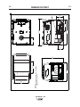
1
RETURN TO MAIN MENU
OUTBACK
For use with machines having Code Numbers:
™
IM972
185
September, 2010
11516
Safety Depends on You
Lincoln arc welding and cutting
equipment is designed and built
with safety in mind. However,
your overall safety can be
increased by proper installation
... and thoughtful operation on
your part. DO NOT INSTALL,
OPERATE OR REPAIR THIS
EQUIPMENT WITHOUT READING THIS MANUAL AND THE
SAFETY PRECAUTIONS CONTAINED THROUGHOUT. And,
most importantly, think before
you act and be careful.
OPERATORʼS MANUAL
®
Copyright © Lincoln Global Inc.
• World's Leader in Welding and Cutting Products •
• Sales and Service through Subsidiaries and Distributors Worldwide •
Cleveland, Ohio 44117-1199 U.S.A. TEL: 216.481.8100 FAX: 216.486.1751 WEB SITE: www.lincolnelectric.com
i
i
SAFETY
WARNING
CALIFORNIA PROPOSITION 65 WARNINGS
Diesel engine exhaust and some of its constituents
are known to the State of California to cause cancer, birth defects, and other reproductive harm.
The Above For Diesel Engines
The engine exhaust from this product contains
chemicals known to the State of California to cause
cancer, birth defects, or other reproductive harm.
The Above For Gasoline Engines
ARC WELDING CAN BE HAZARDOUS. PROTECT YOURSELF AND OTHERS FROM POSSIBLE SERIOUS INJURY OR DEATH.
KEEP CHILDREN AWAY. PACEMAKER WEARERS SHOULD CONSULT WITH THEIR DOCTOR BEFORE OPERATING.
Read and understand the following safety highlights. For additional safety information, it is strongly recommended that you
purchase a copy of “Safety in Welding & Cutting - ANSI Standard Z49.1” from the American Welding Society, P.O. Box
351040, Miami, Florida 33135 or CSA Standard W117.2-1974. A Free copy of “Arc Welding Safety” booklet E205 is available
from the Lincoln Electric Company, 22801 St. Clair Avenue, Cleveland, Ohio 44117-1199.
BE SURE THAT ALL INSTALLATION, OPERATION, MAINTENANCE AND REPAIR PROCEDURES ARE
PERFORMED ONLY BY QUALIFIED INDIVIDUALS.
FOR ENGINE
powered equipment.
1.h. To avoid scalding, do not remove the
radiator pressure cap when the engine is
hot.
1.a. Turn the engine off before troubleshooting and maintenance
work unless the maintenance work requires it to be running.
____________________________________________________
1.b. Operate engines in open, well-ventilated
areas or vent the engine exhaust fumes
outdoors.
____________________________________________________
1.c. Do not add the fuel near an open flame
welding arc or when the engine is running.
Stop the engine and allow it to cool before
refueling to prevent spilled fuel from vaporizing on contact with hot engine parts and
igniting. Do not spill fuel when filling tank. If
fuel is spilled, wipe it up and do not start
engine until fumes have been eliminated.
____________________________________________________
1.d. Keep all equipment safety guards, covers and devices in
position and in good repair.Keep hands, hair, clothing and
tools away from V-belts, gears, fans and all other moving
parts when starting, operating or repairing equipment.
____________________________________________________
1.e. In some cases it may be necessary to remove safety
guards to perform required maintenance. Remove
guards only when necessary and replace them when the
maintenance requiring their removal is complete.
Always use the greatest care when working near moving
parts.
___________________________________________________
1.f. Do not put your hands near the engine fan.
Do not attempt to override the governor or
idler by pushing on the throttle control rods
while the engine is running.
ELECTRIC AND
MAGNETIC FIELDS
may be dangerous
2.a. Electric current flowing through any conductor causes
localized Electric and Magnetic Fields (EMF). Welding
current creates EMF fields around welding cables and
welding machines
2.b. EMF fields may interfere with some pacemakers, and
welders having a pacemaker should consult their physician
before welding.
2.c. Exposure to EMF fields in welding may have other health
effects which are now not known.
2.d. All welders should use the following procedures in order to
minimize exposure to EMF fields from the welding circuit:
2.d.1. Route the electrode and work cables together - Secure
them with tape when possible.
2.d.2. Never coil the electrode lead around your body.
2.d.3. Do not place your body between the electrode and
work cables. If the electrode cable is on your right
side, the work cable should also be on your right side.
2.d.4. Connect the work cable to the workpiece as close as
possible to the area being welded.
___________________________________________________
1.g. To prevent accidentally starting gasoline engines while
turning the engine or welding generator during maintenance
work, disconnect the spark plug wires, distributor cap or
magneto wire as appropriate.
2.d.5. Do not work next to welding power source.
®
ii
ii
SAFETY
ARC RAYS can burn.
ELECTRIC SHOCK can
kill.
3.a. The electrode and work (or ground) circuits
are electrically “hot” when the welder is on.
Do not touch these “hot” parts with your bare
skin or wet clothing. Wear dry, hole-free
gloves to insulate hands.
3.b. Insulate yourself from work and ground using dry insulation.
Make certain the insulation is large enough to cover your full
area of physical contact with work and ground.
In addition to the normal safety precautions, if welding
must be performed under electrically hazardous
conditions (in damp locations or while wearing wet
clothing; on metal structures such as floors, gratings or
scaffolds; when in cramped positions such as sitting,
kneeling or lying, if there is a high risk of unavoidable or
accidental contact with the workpiece or ground) use
the following equipment:
• Semiautomatic DC Constant Voltage (Wire) Welder.
• DC Manual (Stick) Welder.
• AC Welder with Reduced Voltage Control.
4.a. Use a shield with the proper filter and cover
plates to protect your eyes from sparks and
the rays of the arc when welding or observing
open arc welding. Headshield and filter lens
should conform to ANSI Z87. I standards.
4.b. Use suitable clothing made from durable flame-resistant
material to protect your skin and that of your helpers from
the arc rays.
4.c. Protect other nearby personnel with suitable, non-flammable
screening and/or warn them not to watch the arc nor expose
themselves to the arc rays or to hot spatter or metal.
FUMES AND GASES
can be dangerous.
5.a. Welding may produce fumes and gases
hazardous to health. Avoid breathing these
fumes and gases. When welding, keep
your head out of the fume. Use enough
ventilation and/or exhaust at the arc to keep
fumes and gases away from the breathing zone. When
welding with electrodes which require special
ventilation such as stainless or hard facing (see
instructions on container or MSDS) or on lead or
cadmium plated steel and other metals or coatings
which produce highly toxic fumes, keep exposure as
low as possible and within applicable OSHA PEL and
ACGIH TLV limits using local exhaust or mechanical
ventilation. In confined spaces or in some circumstances, outdoors, a respirator may be required.
Additional precautions are also required when welding
on galvanized steel.
3.c. In semiautomatic or automatic wire welding, the electrode,
electrode reel, welding head, nozzle or semiautomatic
welding gun are also electrically “hot”.
3.d. Always be sure the work cable makes a good electrical
connection with the metal being welded. The connection
should be as close as possible to the area being welded.
3.e. Ground the work or metal to be welded to a good electrical
(earth) ground.
3.f. Maintain the electrode holder, work clamp, welding cable and
welding machine in good, safe operating condition. Replace
damaged insulation.
3.g. Never dip the electrode in water for cooling.
3.h. Never simultaneously touch electrically “hot” parts of
electrode holders connected to two welders because voltage
between the two can be the total of the open circuit voltage
of both welders.
3.i. When working above floor level, use a safety belt to protect
yourself from a fall should you get a shock.
5. b. The operation of welding fume control equipment is affected
by various factors including proper use and positioning of
the equipment, maintenance of the equipment and the specific welding procedure and application involved. Worker
exposure level should be checked upon installation and
periodically thereafter to be certain it is within applicable
OSHA PEL and ACGIH TLV limits.
5.c. Do not weld in locations near chlorinated hydrocarbon vapors
coming from degreasing, cleaning or spraying operations.
The heat and rays of the arc can react with solvent vapors to
form phosgene, a highly toxic gas, and other irritating products.
3.j. Also see Items 6.c. and 8.
5.d. Shielding gases used for arc welding can displace air and
cause injury or death. Always use enough ventilation,
especially in confined areas, to insure breathing air is safe.
5.e. Read and understand the manufacturerʼs instructions for this
equipment and the consumables to be used, including the
material safety data sheet (MSDS) and follow your
employerʼs safety practices. MSDS forms are available from
your welding distributor or from the manufacturer.
5.f. Also see item 1.b.
®
iii
iii
SAFETY
WELDING and CUTTING
SPARKS can
cause fire or explosion.
6.a. Remove fire hazards from the welding area.
If this is not possible, cover them to prevent
the welding sparks from starting a fire.
Remember that welding sparks and hot
materials from welding can easily go through small cracks
and openings to adjacent areas. Avoid welding near
hydraulic lines. Have a fire extinguisher readily available.
6.b. Where compressed gases are to be used at the job site,
special precautions should be used to prevent hazardous
situations. Refer to “Safety in Welding and Cutting” (ANSI
Standard Z49.1) and the operating information for the
equipment being used.
6.c. When not welding, make certain no part of the electrode
circuit is touching the work or ground. Accidental contact
can cause overheating and create a fire hazard.
6.d. Do not heat, cut or weld tanks, drums or containers until the
proper steps have been taken to insure that such procedures
will not cause flammable or toxic vapors from substances
inside. They can cause an explosion even though they have
been “cleaned”. For information, purchase “Recommended
Safe Practices for the Preparation for Welding and Cutting of
Containers and Piping That Have Held Hazardous
Substances”, AWS F4.1 from the American Welding Society
(see address above).
6.e. Vent hollow castings or containers before heating, cutting or
welding. They may explode.
CYLINDER may explode
if damaged.
7.a. Use only compressed gas cylinders
containing the correct shielding gas for the
process used and properly operating
regulators designed for the gas and
pressure used. All hoses, fittings, etc. should be suitable for
the application and maintained in good condition.
7.b. Always keep cylinders in an upright position securely
chained to an undercarriage or fixed support.
7.c. Cylinders should be located:
• Away from areas where they may be struck or subjected to
physical damage.
• A safe distance from arc welding or cutting operations and
any other source of heat, sparks, or flame.
7.d. Never allow the electrode, electrode holder or any other
electrically “hot” parts to touch a cylinder.
7.e. Keep your head and face away from the cylinder valve outlet
when opening the cylinder valve.
7.f. Valve protection caps should always be in place and hand
tight except when the cylinder is in use or connected for
use.
7.g. Read and follow the instructions on compressed gas
cylinders, associated equipment, and CGA publication P-l,
“Precautions for Safe Handling of Compressed Gases in
Cylinders,” available from the Compressed Gas Association
1235 Jefferson Davis Highway, Arlington, VA 22202.
6.f. Sparks and spatter are thrown from the welding arc. Wear oil
free protective garments such as leather gloves, heavy shirt,
cuffless trousers, high shoes and a cap over your hair. Wear
ear plugs when welding out of position or in confined places.
Always wear safety glasses with side shields when in a
welding area.
6.g. Connect the work cable to the work as close to the welding
area as practical. Work cables connected to the building
framework or other locations away from the welding area
increase the possibility of the welding current passing
through lifting chains, crane cables or other alternate circuits. This can create fire hazards or overheat lifting chains
or cables until they fail.
6.h. Also see item 1.c.
FOR ELECTRICALLY
powered equipment.
8.a. Turn off input power using the disconnect
switch at the fuse box before working on
the equipment.
8.b. Install equipment in accordance with the U.S. National
Electrical Code, all local codes and the manufacturerʼs
recommendations.
8.c. Ground the equipment in accordance with the U.S. National
Electrical Code and the manufacturerʼs recommendations.
6.I. Read and follow NFPA 51B “ Standard for Fire Prevention
During Welding, Cutting and Other Hot Work”, available
from NFPA, 1 Batterymarch Park, PO box 9101, Quincy, Ma
022690-9101.
6.j. Do not use a welding power source for pipe thawing.
Refer to http://www.lincolnelectric.com/safety for additional safety information.
®
iv
SAFETY
PRÉCAUTIONS DE SÛRETÉ
Pour votre propre protection lire et observer toutes les instructions
et les précautions de sûreté specifiques qui parraissent dans ce
manuel aussi bien que les précautions de sûreté générales suivantes:
Sûreté Pour Soudage A LʼArc
1. Protegez-vous contre la secousse électrique:
a. Les circuits à lʼélectrode et à la piéce sont sous tension
quand la machine à souder est en marche. Eviter toujours
tout contact entre les parties sous tension et la peau nue
ou les vétements mouillés. Porter des gants secs et sans
trous pour isoler les mains.
b. Faire trés attention de bien sʼisoler de la masse quand on
soude dans des endroits humides, ou sur un plancher
metallique ou des grilles metalliques, principalement dans
les positions assis ou couché pour lesquelles une grande
partie du corps peut être en contact avec la masse.
c. Maintenir le porte-électrode, la pince de masse, le câble
de soudage et la machine à souder en bon et sûr état
defonctionnement.
d.Ne jamais plonger le porte-électrode dans lʼeau pour le
refroidir.
e. Ne jamais toucher simultanément les parties sous tension
des porte-électrodes connectés à deux machines à souder
parce que la tension entre les deux pinces peut être le
total de la tension à vide des deux machines.
f. Si on utilise la machine à souder comme une source de
courant pour soudage semi-automatique, ces precautions
pour le porte-électrode sʼapplicuent aussi au pistolet de
soudage.
2. Dans le cas de travail au dessus du niveau du sol, se protéger
contre les chutes dans le cas ou on recoit un choc. Ne jamais
enrouler le câble-électrode autour de nʼimporte quelle partie
du corps.
3. Un coup dʼarc peut être plus sévère quʼun coup de soliel,
donc:
a. Utiliser un bon masque avec un verre filtrant approprié
ainsi quʼun verre blanc afin de se protéger les yeux du rayonnement de lʼarc et des projections quand on soude ou
quand on regarde lʼarc.
b. Porter des vêtements convenables afin de protéger la
peau de soudeur et des aides contre le rayonnement de
lʻarc.
c. Protéger lʼautre personnel travaillant à proximité au
soudage à lʼaide dʼécrans appropriés et non-inflammables.
4. Des gouttes de laitier en fusion sont émises de lʼarc de
soudage. Se protéger avec des vêtements de protection libres
de lʼhuile, tels que les gants en cuir, chemise épaisse, pantalons sans revers, et chaussures montantes.
iv
5. Toujours porter des lunettes de sécurité dans la zone de
soudage. Utiliser des lunettes avec écrans lateraux dans les
zones où lʼon pique le laitier.
6. Eloigner les matériaux inflammables ou les recouvrir afin de
prévenir tout risque dʼincendie dû aux étincelles.
7. Quand on ne soude pas, poser la pince à une endroit isolé de
la masse. Un court-circuit accidental peut provoquer un
échauffement et un risque dʼincendie.
8. Sʼassurer que la masse est connectée le plus prés possible
de la zone de travail quʼil est pratique de le faire. Si on place
la masse sur la charpente de la construction ou dʼautres
endroits éloignés de la zone de travail, on augmente le risque
de voir passer le courant de soudage par les chaines de levage, câbles de grue, ou autres circuits. Cela peut provoquer
des risques dʼincendie ou dʼechauffement des chaines et des
câbles jusquʼà ce quʼils se rompent.
9. Assurer une ventilation suffisante dans la zone de soudage.
Ceci est particuliérement important pour le soudage de tôles
galvanisées plombées, ou cadmiées ou tout autre métal qui
produit des fumeés toxiques.
10. Ne pas souder en présence de vapeurs de chlore provenant
dʼopérations de dégraissage, nettoyage ou pistolage. La
chaleur ou les rayons de lʼarc peuvent réagir avec les vapeurs
du solvant pour produire du phosgéne (gas fortement toxique)
ou autres produits irritants.
11. Pour obtenir de plus amples renseignements sur la sûreté,
voir le code “Code for safety in welding and cutting” CSA
Standard W 117.2-1974.
PRÉCAUTIONS DE SÛRETÉ POUR
LES MACHINES À SOUDER À
TRANSFORMATEUR ET À
REDRESSEUR
1. Relier à la terre le chassis du poste conformement au code de
lʼélectricité et aux recommendations du fabricant. Le dispositif
de montage ou la piece à souder doit être branché à une
bonne mise à la terre.
2. Autant que possible, Iʼinstallation et lʼentretien du poste seront
effectués par un électricien qualifié.
3. Avant de faires des travaux à lʼinterieur de poste, la debrancher à lʼinterrupteur à la boite de fusibles.
4. Garder tous les couvercles et dispositifs de sûreté à leur
place.
®
v
Thank You
v
for selecting a QUALITY product by Lincoln Electric. We want you
to take pride in operating this Lincoln Electric Company product
••• as much pride as we have in bringing this product to you!
CUSTOMER ASSISTANCE POLICY
The business of The Lincoln Electric Company is manufacturing and selling high quality welding equipment, consumables, and cutting equipment. Our challenge is to meet the needs of our customers and to exceed their expectations. On occasion, purchasers may ask Lincoln
Electric for advice or information about their use of our products. We respond to our customers based on the best information in our possession at that time. Lincoln Electric is not in a position to warrant or guarantee such advice, and assumes no liability, with respect to such information or advice. We expressly disclaim any warranty of any kind, including any warranty of fitness for any customerʼs particular purpose,
with respect to such information or advice. As a matter of practical consideration, we also cannot assume any responsibility for updating or
correcting any such information or advice once it has been given, nor does the provision of information or advice create, expand or alter any
warranty with respect to the sale of our products.
Lincoln Electric is a responsive manufacturer, but the selection and use of specific products sold by Lincoln Electric is solely within the control
of, and remains the sole responsibility of the customer. Many variables beyond the control of Lincoln Electric affect the results obtained in
applying these types of fabrication methods and service requirements.
Subject to Change – This information is accurate to the best of our knowledge at the time of printing. Please refer to www.lincolnelectric.com
for any updated information.
Please Examine Carton and Equipment For Damage Immediately
When this equipment is shipped, title passes to the purchaser upon receipt by the carrier. Consequently, Claims
for material damaged in shipment must be made by the purchaser against the transportation company at the
time the shipment is received.
Please record your equipment identification information below for future reference. This information can be
found on your machine nameplate.
Product _________________________________________________________________________________
Model Number ___________________________________________________________________________
Code Number or Date Code_________________________________________________________________
Serial Number____________________________________________________________________________
Date Purchased___________________________________________________________________________
Where Purchased_________________________________________________________________________
Whenever you request replacement parts or information on this equipment, always supply the information you
have recorded above. The code number is especially important when identifying the correct replacement parts.
On-Line Product Registration
- Register your machine with Lincoln Electric either via fax or over the Internet.
• For faxing: Complete the form on the back of the warranty statement included in the literature packet
accompanying this machine and fax the form per the instructions printed on it.
• For On-Line Registration: Go to our WEB SITE at www.lincolnelectric.com. Choose “Quick Links” and then
“Product Registration”. Please complete the form and submit your registration.
Read this Operators Manual completely before attempting to use this equipment. Save this manual and keep it
handy for quick reference. Pay particular attention to the safety instructions we have provided for your protection.
The level of seriousness to be applied to each is explained below:
WARNING
This statement appears where the information must be followed exactly to avoid serious personal injury or loss of life.
CAUTION
This statement appears where the information must be followed to avoid minor personal injury or damage to this equipment.
vi
vi
TABLE OF CONTENTS
Page
Installation.......................................................................................................................Section A
Technical Specifications .......................................................................................................A-1
Safety Precautions. ..............................................................................................................A-2
Location and Ventilation ................................................................................................A-2
Storing ...........................................................................................................................A-2
Stacking ........................................................................................................................A-3
Tilting.............................................................................................................................A-3
Lifting.............................................................................................................................A-3
Pre-Operation Engine Service..............................................................................................A-3
Oil ..................................................................................................................................A-3
Fuel ...............................................................................................................................A-3
Spark Arrester ...............................................................................................................A-3
Electrical and Welding Connections .....................................................................................A-4
Machine Grounding .......................................................................................................A-5
Plugs and Hand-Held Equipment, Auxiliary Power Receptacles .........................................A-6
Premises Wiring ...................................................................................................................A-6
Circuit Breakers ....................................................................................................................A-6
Electrical Devices used with the Outback™ 185 ..................................................................A-7
________________________________________________________________________________
Operation.........................................................................................................................Section B
Safety Instructions ................................................................................................................B-1
Symbols................................................................................................................................B-2
General Description..............................................................................................................B-3
Recommended Applications.................................................................................................B-3
Operational Features and Controls ......................................................................................B-3
Design Features and Advantages ........................................................................................B-3
Welding Capability................................................................................................................B-3
Limitations ............................................................................................................................B-3
Controls and Settings ...........................................................................................................B-4
Welder/Generator Controls ..................................................................................................B-4
Engine Operation .................................................................................................................B-5
Welding Operation................................................................................................................B-6
Auxiliary Power.....................................................................................................................B-7
Electrode selection Guide .............................................................................................B-7
Auxiliary Power Application ..................................................................................................B-8
________________________________________________________________________________
Accessories .....................................................................................................Section C
General Options / Accessories ..............................................................................C-1
________________________________________________________________________
Maintenance ....................................................................................................Section D
Safety Precautions ................................................................................................D-1
Routine and Periodic Engine Maintenance....................................................D-1, D-2
________________________________________________________________________
Troubleshooting ..............................................................................................Section E
How to Use Troubleshooting Guide.......................................................................E-1
Troubleshooting Guide.............................................................................E-2 thru E-4
________________________________________________________________________
Wiring Diagram and Dimension Print ............................................................Section F
________________________________________________________________________
Parts List .....................................................................................................P-591 Series
________________________________________________________________________
A-1
A-1
INSTALLATION
TECHNICAL SPECIFICATIONS - OUTBACK™ 185 (K2706-1)
INPUT - GASOLINE ENGINE
Make/Model
Description
KOHLER
CS 12.75
Speed (RPM)
1 cylinder
3750RPM High Idle
4 cycle
1825RPM Low Idle
air-cooled
3400RPM Full Load
OHV gasoline
12.75 HP @
3600 RPM
Aluminum Block
Displacement
21.96 cu. in
(360 cc)
Ignition
System
Capacities
Electric & Recoil
Start;
Fuel: 6.86 gal.
(24.9L)
Manual
Choke
Oil: 1.2 Qts.
(1.1L)
Bore x Stroke
3.35” x 2.48”
(85 mm x 63mm)
w/ Cast Iron Sleeve
RATED OUTPUT - WELDER
AMPS @ DC CONSTANT CURRENT
DUTY CYCLE
100
130
150
185
VOLTS @ RATED AMPERES
100%
60%
20%
MAX OUTPUT
25
25
25
---
OUTPUT -WELDER AND GENERATOR
Welding Ranges
Welding Open Circuit Voltage
50 - 185 Amps DC
80 VDC Max.
AC Auxiliary Power
4600 Watts 115V 1PH
100% Duty Cycle
5700 Peak Watts
5200 Continuous Watts
120 / 230 V 1PH
PHYSICAL DIMENSIONS
HEIGHT
WIDTH
DEPTH
WEIGHT
25.47 in.
21.12 in.
31.48 in.
310.0 lbs.
646.94 mm
536.45 mm
799.59 mm
140.6 kg
OPERATING TEMPERATURE RANGE
STORAGE TEMPERATURE RANGE
0° F TO 104° F (-18° C TO 40° C)
-40° F TO 131° F (-40° C TO 55° C)
OUTBACK™ 185
®
A-2
INSTALLATION
A-2
SAFETY PRECAUTIONS
LOCATION AND VENTILATION
Read this entire installation section before you
start installation.
Whenever you use the OUTBACK™ 185, be sure that
clean cooling air can flow around the machineʼs gasoline
engine and the generator. Avoid dusty, dirty areas. Also,
keep the machine away from heat sources. Do not place the
back end of the generator anywhere near hot engine
exhaust from another machine. And of course, make sure
that engine exhaust is ventilated to an open, outside area.
WARNING
Do not attempt to use this equipment until you
have thoroughly read all operating and maintenance manuals supplied with your machine. They
include important safety precautions, detailed
engine starting, operating and maintenance
instructions, and parts lists.
Hazards of Electric Shock, Engine
Exhaust & Moving Parts
WARNING
The OUTBACK™ 185 must be used outdoors. Do not set
the machine in puddles or otherwise submerge it in water.
Such practices pose safety hazards and cause improper
operation and corrosion of parts.
Always operate the OUTBACK™ 185 with the case roof
on and all machine components completely assembled. This
will help to protect you from the dangers of moving parts,
hot metal surfaces, and live electrical devices.
STORING
ELECTRIC SHOCK can kill.
• Do not touch electrically live parts
or electrode with skin or wet clothing.
• Insulate yourself from work and
ground.
• Always wear dry insulating gloves.
ENGINE EXHAUST can kill.
1.
2.
3.
• Use in open, well ventilated areas
or vent exhaust outside.
• Do not stack anything on or near
the engine.
4.
5.
MOVING PARTS can injure.
• Do not operate with doors open or
guards off.
• Stop engine before servicing.
6.
• Keep away from moving parts.
Only qualified personnel should install, use, or
service this equipment.
7.
Store the machine in a cool, dry place when it is not in
use. Protect it from dust and dirt. Keep it where it can
not be accidentally damaged from construction activities, moving vehicles and other hazards.
If you will be storing the machine for over 30 days, you
should drain the fuel to protect fuel system and carburetor parts from gum deposits. Empty all fuel from the
tank and run the engine until it stops from lack of fuel.
You can store the machine for up to 24 months if you
use a stabilizing Additive in the fuel system. Mix the
additive with the fuel in the tank and run the engine for
a short time to circulate the additive through the carburetor.
While the engine is still warm, drain the oil and refill with
fresh 10W30 oil.
Remove the spark plug and pour approximately 1/2
ounce (15ml) of engine oil into the cylinder. Replace the
spark plug and crank the engine slowly to distribute the
oil.
Clean any dirt and debris from the cylinder and cylinder
head fins and housing, rotating screen, and muffler
areas.
Store in a clean, dry area.
OUTBACK™ 185
®
A-3
A-3
INSTALLATION
STACKING
OIL
OUTBACK™ 185 machines CANNOT be stacked.
The OUTBACK™ 185 is shipped with the engine
filled with SAE 10W30 oil. CHECK THE OIL LEVEL
BEFORE YOU START THE ENGINE. This is an
added precaution. Do not screw in dipstick when
checking oil level. DO NOT OVERFILL. Be sure the
fill plug is tight after servicing.
TILTING
Place the machine on a secure, level surface whenever you use it or store it. Any surfaces you place it on
other than the ground must be firm, non-skid, and
structurally sound.
FUEL
The gasoline engine is designed to run in a level position for best performance. It can operate at an angle,
but this should never be more than 15 degrees in any
direction. If you do operate it at a slight angle, be sure
to check the oil regularly and keep the oil level full.
Also, fuel capacity will be a little less at an angle.
Fill the fuel tank with clean, fresh, regular grade (minimum 87 octane lead free gasoline. DO NOT MIX OIL
WITH GAS. The OUTBACK™ 185 capacity is approximately 6.8 gallons (25.74 Liter). DO NOT OVERFILL, allow room in the fuel tank for fuel expansion.
LIFTING
SPARK ARRESTER
The OUTBACK™ 185 should be lifted by two people.
(See Specification section for weight). The LowLift™
grab bars on both ends make lifting easier.
Some federal, state or local laws may require gasoline engines to be equipped with exhaust spark
arresters when they are operated in certain locations
where unarrested sparks may present a fire hazard.
The standard muffler included with this machine does
not qualify as a spark arrester. For areas requiring
spark arrestors, use K2793-1.
PRE-OPERATION ENGINE SERVICE
Read and understand the engine operating and
maintenance instructions supplied with this machine
before you operate the OUTBACK™ 185.
CAUTION
An incorrect additional arrester may lead to damage to the engine or adversely affect performance.
------------------------------------------------------------------------
WARNING
• Keep hands away from muffler or HOT engine
parts.
• Stop the engine when fueling.
• Do not smoke when fueling.
• Remove fuel cap slowly to release pressure.
• Do not overfill tank.
• Wipe up spilled fuel and allow fumes to clear
before starting engine.
• Keep sparks and flame away from tank.
------------------------------------------------------------------------
OUTBACK™ 185
®
A-4
A-4
INSTALLATION
OUTBACK™ 185 OUTPUT CONNECTIONS
2
3
10
6
9
8
7
1
4
5
1
8
4
7
9
5
6
10
3
2
FIGURE A.1
1.
2.
3.
4.
5.
6.
CURRENT CONTROL DIAL
WELD OUTPUT TERMINALS (2)
GROUND STUD
CIRCUIT BREAKERS (2) - 20 AMP
CIRCUIT BREAKER 30 Amp
RECEPTACLE - 240 VOLT, 50 AMP
7. DUPLEX RECEPTACLE (2)- 120 VOLT, 20 AMP
8. HOURMETER
9. ENGINE SWITCH
10. CHOKE
ELECTRICAL OUTPUT CONNECTIONS
TABLE A.1
RECOMMENDED WELDING CABLE
SIZE AND LENGTH
See Figure A.1 for the location of the current control
dial, weld output terminals, ground stud, circuit breakers, 240 and 120 volt receptacles.
TOTAL COMBINED LENGTH OF
ELECTRODE AND WORK CABLES
WELDING CABLE CONNECTIONS
Cable
Length
125 Amps
30% Duty Cycle
Cable Size and Length
Be sure to use welding cables that are large enough.
The correct size and length becomes especially important when you are welding at a distance from the
welder.
Table A.1 lists recommended cable sizes and lengths
for rated current and duty cycle. Length refers to the
distance from the welder to the work and back to the
welder. Cable diameters are increased for long cable
lengths to reduce voltage drops.
0-50 ft (0-15m)
6 AWG
50-100 ft (15-30 m)
5 AWG
100-150 ft (30-46 m)
3 AWG
150-200 ft (46-61 m)
2 AWG
200-250 ft (61-76m)
1 AWG
OUTBACK™ 185
®
A-5
A-5
INSTALLATION
Cable Installation
MACHINE GROUNDING
Install the welding cables to your OUTBACK™ 185 as
follows. See Figure A.1 for the location of parts.
Because this portable engine driven welder or generator creates its own power, it is not necessary to connect its frame to an earth ground, unless the machine
is connected to premises wiring (your home, shop,
etc.).
1. The gasoline engine must be OFF to install welding cables.
2. Remove the 1/2-13 flanged nuts from the output
terminals.
3. Connect the electrode holder and work cables to
the weld output terminals. Normally, the electrode
cable is connected to the positive (+) output stud.
4. Tighten the flanged nuts securely.
5. Be certain that the metal piece you are welding
(the “work”) is securely connected to the work
clamp and cable.
6. Check and tighten the connections periodically.
CAUTION
• Loose connections will cause the output studs to
overheat and the studs may eventually melt.
• Do not cross welding cables at output stud connection. Keep isolated and separate from one another.
------------------------------------------------------------------------
Lincoln Electric offers a welding accessory kit with #6
welding cables. See the ACCESSORIES section of
this manual for more information.
To prevent dangerous electric shock, other equipment
to which this engine driven welder supplies power,
must:
a) be grounded to the frame of the welder using a
grounded type plug
or
b) be double insulated
When this welder is mounted on a truck or trailer, the
machine grounding
stud must be securely connected to the metal frame of the vehicle.
In general if the machine is to be grounded, it should
be connected with a #8 or larger copper wire to a solid
earth ground such as a metal water pipe going into
the ground for at least ten feet and having no insulated joints, or to the metal framework of a building
which has been effectively grounded. The U.S.
National Electrical Code lists a number of alternate
means of grounding electrical equipment. A machine
grounding stud marked with the symbol
is provided on the front of the welder.
WARNING
DO NOT GROUND MACHINE TO A PIPE WHICH
CARRIES EXPLOSIVE OR COMBUSTIBLE
MATERIAL.
------------------------------------------------------------------------
For more information on welding , see WELDING
OPERATION in the OPERATION section of this manual.
OUTBACK™ 185
®
A-6
A-6
INSTALLATION
PLUGS AND HAND HELD EQUIPMENT
PREMISES WIRING
For further protection against electric shock, any electrical equipment connected to the generator receptacles must use a three-blade, grounded type plug or an
Underwriterʼs Laboratories (UL) approved double
insulated tool with a two blade plug.
The OUTBACK™ 185 is not recommended for
premises wiring. The OUTBACK™ 185 does not have
a combined 120/240 volt receptacle and cannot be
connected to a premises as described in other Lincoln
literature.
WARNING
Never operate this machine with damaged or
defective cords. All electrical equipment must be
in safe operating condition.
------------------------------------------------------------------------
AUXILIARY POWER RECEPTACLES
The control panel of the OUTBACK™ 185 features
three auxiliary power receptacles:
•
Two 20 amp,120 volt duplex (double outlet)
receptacle.
•
A 50 amp, 240 volt single outlet receptacle.
See Figure A.1
Through these receptacles the machine can supply up
to 5700 watts surge or 5200 watts continuous of single-phase 60 Hertz AC power. The machine output
voltages meet UL standards and fall within ± 10% of
the rated voltage.
The OUTBACK™ 185 is intended only for backup,
intermittent use power. Certain electrical devices cannot be powered by the OUTBACK™ 185. Refer to
Table A.2 for these devices.
CIRCUIT BREAKERS
Auxiliary power is protected by circuit breakers. When
the machine is operated in high temperature environments, the breakers may tend to trip at lower loads
than normally.
CAUTION
NEVER BYPASS THE CIRCUIT BREAKERS.
WITHOUT OVERLOAD PROTECTION, THE UNIT
COULD OVERHEAT AND/OR CAUSE DAMAGE TO
THE EQUIPMENT BEING USED.
------------------------------------------------------------------------
OUTBACK™ 185
®
A-7
A-7
INSTALLATION
CAUTION
Certain Electrical devices cannot be powered by the OUTBACK™ 185. See Table A.2
TABLE A.2
ELECTRICAL DEVICE USE WITH THE OUTBACK™ 185
Type
Common Electrical Devices
Possible Concerns
Resistive
Heaters, toasters, incandescent
light bulbs, electric range, hot
pan, skillet, coffee maker.
NONE
Capacitive
TV sets, radios, microwaves,
appliances with electrical control.
Voltage spikes or high voltage
regulation can cause the capacitative elements to fail. Surge
protection, transient protection, and
additional loading is recommended for 100% fail-safe operation. DO NOT RUN
THESE DEVICES WITHOUT
ADDITIONAL RESISTIVE TYPE
LOADS.
Inductive
Single-phase induction motors,
drills, well pumps, grinders, small
refrigerators, weed and hedge
trimmers.
These devices require large
current inrush for starting. (See
Table B.3, GENERATOR POWER
APPLICATIONS, in the OPERATION section of this manual for
required starting wattages.)
Some synchronous motors may
be frequency sensitive to attain
maximum output torque, but
they SHOULD BE SAFE from
any frequency induced failures.
Capacitive / Inductive
Computers, high resolution TV sets,
complicated electrical equipment.
An inductive type line conditioner along with transient and
surge protection is required,
and liabilities still exist.
DO NOT USE THESE DEVICES
WITH A OUTBACK™ 185.
The Lincoln Electric Company is not responsible for any damage to electrical components
improperly connected to a OUTBACK™ 185.
OUTBACK™ 185
®
B-1
B-1
OPERATION
SAFETY INSTRUCTIONS
WARNING
WARNING
ELECTRIC SHOCK
can kill.
ENGINE EXHAUST can kill.
• Use in open, well ventilated areas
or vent exhaust outside.
• Do not touch electrically live parts
or electrode with skin or wet
clothing.
• Do not stack anything on or near
the engine.
• Insulate yourself from work and
ground.
MOVING PARTS can injure.
• Do not operate with doors open or
guards off.
• Always wear dry insulating
gloves.
• Stop engine before servicing.
• Keep away from moving parts.
FUMES AND GASES
can be dangerous.
Only qualified personnel should install, use, or
service this equipment.
• Keep your head out of fumes.
• Use ventilation or exhaust to
remove fumes from breathing
zone.
Observe additional Safety Guidelines detailed
throughout this manual.
WELDING SPARKS
can cause fire or
explosion
• Keep flammable material away.
• Do not weld on containers that
have held combustibles.
ARC RAYS
can burn.
• Wear eye, ear and body
protection.
OUTBACK™ 185
®
B-2
B-2
OPERATION
GRAPHIC SYMBOLS USED ON THIS EQUIPMENT OR IN THIS MANUAL
WARNING /
CAUTION
CHOKE
OIL
AIR CLEANER
FUEL
CIRCUIT
BREAKER
GROUND
(AUXILIARY
POWER)
WORK CLAMP
FAST
ELECTRODE
WELDING ARC
SLOW
ENGINE OFF
ENGINE START
AUTO IDLE
OUTBACK™ 185
®
B-3
OPERATION
GENERAL DESCRIPTION
The OUTBACK™ 185 is designed for commercial use
welder/generator applications. As a welder it provides
185 amps of DC constant current for welding with DC
stick electrodes. A single dial lets you select a full
range of welding output from 50 to 185 amps.
As a generator it can supply up to 5700 surge watts or
5200 continuous watts of 120 / 240 volt, single-phase
AC power. The machine is portable.
A Kohler CS 12.75 HP air cooled, OHV gasoline
engine powers the welder / generator. It has an
engine warranty of 3 years.
RECOMMENDED APPLICATIONS
Welder
The OUTBACK™ 185 provides excellent constant
current DC welding output for stick (SMAW) welding.
Generator
The OUTBACK™ 185 gives smooth AC generator
output for continuous auxiliary power usage within the
engine manufacturerʼs required maintenance recommendations.
OPERATIONAL FEATURES AND
CONTROLS
The OUTBACK™ 185 was designed for simplicity.
Therefore, it has very few operating controls. A single
dial on the control panel lets you select either welder
or generator use. For welding, the same dial selects
continuous current output over the machineʼs 50 to
185 amp range.
The gasoline engine controls include a recoil starter,
choke and stop switch. See ENGINE OPERATION in
the OPERATION section of this manual for details
about starting, running, stopping, and breaking in the
gasoline engine.
B-3
DESIGN FEATURES AND
ADVANTAGES
• 185 amp DC constant current welding for stick
electrodes.
• Lightweight / portable.
• Full range, continuous welding output control with
a single knob.
• Automatic shutdown under low oil level condition.
• Hour Meter Standard.
• 5700 Surge watts or 5200 Watts of continuous
120 / 240 volt single phase AC auxiliary power.
• Kohler CS 12.75 HP overhead cam air-cooled
gasoline engine. Smooth running, long life.
WELDING CAPABILITY
The OUTBACK™ 185 rated 185 amps, 20 VDC at
10% duty cycle on a ten-minute basis. This means
that you can load the welder to 185 amps for one
minute out of every ten-minute period. The machine
is capable of higher duty cycles at lower output currents. For example, you can load the welder to 120
amps for ten minutes out of ten for a 100% duty cycle.
The current is continuously variable from 50 to 185
amps DC. The OUTBACK™ 185 can, therefore, weld
with all 3/32”, 1/8” and most 5/32” diameter Lincoln
DC electrodes.
LIMITATIONS
• The OUTBACK™ 185 is not recommended for any
processes besides those that are normally performed using stick welding (SMAW) procedures.
• The OUTBACK™ 185 is not recommended for
pipe thawing.
• During welding, generator power is limited to 100
watts, and output voltages can drop from 120 to 80
volts and 240 to 160 volts. Therefore, DO NOT
OPERATE ANY SENSITIVE ELECTRICAL
EQUIPMENT WHILE YOU ARE WELDING.
OUTBACK™ 185
®
B-4
B-4
OPERATION
CONTROLS AND SETTINGS All welder/generator controls are located on the Output Control Panel.
Gasoline engine controls are mounted on the engine. See Figure B.1 and the figures in engine operation section.
OUTPUT PANEL CONTROLS
3 or 4
6
5
11
8
12
10
1
9
7
2
10
1
9
12
7
2
8
11
5
6
3 or 4
WELDER/GENERATOR CONTROLS
See Figure B.1 for the location of the following features:
1. CURRENT CONTROL DIAL: Adjusts continuous current output. The amperages on the dial correspond to
the approximate amperages needed for specific
Lincoln welding electrodes.
2. 30 AMP CIRCUIT BREAKER: Provide separate overload current protection for the 120 Volt and 240 Volt
Receptacles
FIGURE B.1
10. HOUR METER: Records the time that the engine
has run for maintenance purposes.
11. ENGINE CHOKE: Engine starting aid.
12. ENGINE SWITCH:
Used to start the engine, Select High Idle or Auto Idle
while the engine is running and stops the engine.
When placed in the “OFF”
position, the ignition
3. WELD POSITIVE OUTPUT TERMINAL: Provides the
connection point for either the electrode holder or the
work cable. (Because the OUTBACK™ 185 is a DC
output machine, either output terminal can be used for
either cable.)
circuit is de-energized to shut down the engine.
4. WELD NEGATIVE OUTPUT TERMINAL: Provides the
connection point for either the electrode holder or the
work cable. (Because the OUTBACK™185 is a DC
output machine, either output terminal can be used for
either cable.)
When in “HIGH IDLE” (
) position, the engine
will run continuously at high idle.
5. GROUND STUD: Provides a connection point for connecting the machine case to earth ground for the
safest grounding procedure.
6. CIRCUIT BREAKER: Provides overload protection for
weld output terminals.
7. CIRCUIT BREAKERS (2): Provide separate overload
current protection for the 120 volt and 240 volt receptacles
8. 240 VOLT RECEPTACLE: Connection point for supplying 250 volt power to operate one electrical device.
9. 120 VOLT DUPLEX RECEPTACLES (2): Connection
point for supplying 120 volt power to operate devices
needed for maintenance purposes.
When held in the “START”
starter motor is energized.
position, the engine
When in “AUTO IDLE” (
/
) position, the
engine will run continuously and the idler operates as
follows:
• Welding
When the electrode touches the work, the welding
arc is initiated and the engine accelerates to full
speed. After welding ceases (and no auxiliary power
is being drawn), the engine will return to low idle
after approximately 10 to 14 seconds.
• Auxiliary Power
With the engine running at low idle and auxiliary
power for lights or tools is drawn (approximately 0150 watts or greater) from the receptacles, the
engine will accelerate to high speed. If no power is
being drawn from the receptacles (and not welding)
for 10-14 seconds, the idler reduces the engine
speed to low idle.
OUTBACK™ 185
®
B-5
B-5
OPERATION
ENGINE OPERATION
Break-in Period
Starting/Shutdown Instructions
It is normal for any engine to use larger quantities of
oil until break-in is accomplished. Check the oil level
twice a day during the break-in period (about 50 running hours). Change the oil after the first 5 hours of
operation. See the Engine Instruction Manual for further details.
Be sure all Pre-Operation Engine Service has been
performed. Also, Read owners manual before starting
for the first time. (See INSTALLATION section)
Remove all loads connected to the AC power receptacles. Before starting, first open the fuel shutoff valve.
Always pull the choke control out when starting the
engine; cold, warm or hot.
Turn the engine switch to the “Start”
position and
crank the engine until it starts, slowly return the choke
control to the full “in” position (choke open), and turn
the switch to the Auto Idle (
/
) position.
Do not turn the switch to the “start” position while the
engine is running because this will cause damage to
the ring gear and/or starter motor.
Stopping the Engine
Remove all welding and auxiliary power loads and
allow engine to run for a few minutes to cool the
engine.
Stop the engine by placing the engine switch in the
“Off” (
) position.
CAUTION
IN ORDER TO ACCOMPLISH THIS BREAK-IN, THE
UNIT SHOULD BE SUBJECTED TO MODERATE
LOADS, WITHIN THE RATING OF THE MACHINE.
AVOID LONG IDLE RUNNING PERIODS. REMOVE
LOADS AND ALLOW ENGINE TO COOL SEVERAL
MINUTES AT LOW IDLE BEFORE SHUTDOWN.
------------------------------------------------------------------------
Low Oil Sensing
This engine has a built in sensor which responds to
low oil level (not pressure). When activated, the system will shut the engine down. The engine will not
restart until sufficient oil is added. Check oil level frequently and add oil as required to the full mark on the
dipstick. DO NOT OVERFILL.
Typical Fuel Consumption
KOHLER CS 12.75 HP
WARNING
Close the fuel valve when the machine is
transported to prevent fuel leakage from
the carburetor.
------------------------------------------------------------------------
NO LOAD.
2250 R.P.M
.20 GALLONS/HOUR
.75 ( LITERS/HOUR)
NO LOAD
3750 R.P.M.
.40 GALLONS/HOUR
1.51 ( LITERS/HOUR)
DC CC WELD OUTPUT
100 AMPS, 25 VOLTS
.73 GALLONS/HOUR
2.77 ( LITERS/HOUR)
AUXILIARY POWER
5200 KVA
.99 GALLONS/HOUR
3.74 ( LITERS/HOUR)
OUTBACK™ 185
®
B-6
OPERATION
WELDING OPERATION
WARNING
ELECTRIC SHOCK can kill.
• Do not touch electrically live parts
or electrode with skin or wet clothing.
• Insulate yourself from work and
ground.
• Always wear dry insulating gloves.
ENGINE EXHAUST can kill.
• Use in open, well ventilated areas
or vent exhaust outside.
• Do not stack anything on or near
the engine.
MOVING PARTS can injure.
• Do not operate with doors open or
guards off.
• Stop engine before servicing.
• Keep away from moving parts.
Only qualified personnel should install, use, or
service this equipment.
The OUTBACK™ 185 can deliver from 50 to 185
amps of welding output current . Output can be
adjusted by setting the current control dial on the output control panel.
You can get maximum welding output by setting the
dial to 185 AMPS. At high current settings like this,
some output may decrease as the machine is used. If
you are welding for a long time, you may need to turn
the dial slightly upward to maintain the same results.
The numbers on the dial correspond to the approximate amps needed to weld using specific Lincoln
welding rods. Table B.2, WELDING APPLICATIONS,
give you the recommended dial settings based on the
thickness of the work and the size and type of rod
youʼre using.
TO USE THE OUTBACK 185 FOR WELDING:
1. Remove the flange nuts from the weld output terminals and place the work and electrode welding
cables over the terminals. See Figure B.1 and
B.1a. Replace and tighten the flange nuts
securely. Be sure the connections are tight.
2.
Select the appropriate electrode. See Table B.2
3.
Attach the work clamp securely to the work you are
welding.
B-6
4. Insert the electrode into the electrode holder.
5. Set the current control dial to the desired output
current .
6. Start the gasoline engine.
See ENGINE OPERATION in this section of
the manual.
7. Strike an arc and begin welding.
AFTER YOU FINISH THE WELD:
1.
Stop the gasoline engine. See ENGINE OPERATION in this section of the manual.
2. Allow the electrode and work to cool completely.
3. Remove the work clamp from the work.
4. Remove any remaining piece of electrode from the
electrode holder.
5. If you are finished using the OUTBACK 185 for welding, disconnect the welding cables from the weld output terminals. Reattach the flange nuts and leave
them on the terminals.
For DC+ welding, the electrode cable is to be connected
to the “+” output stud and work cable to the “-” output
stud. (For DC- welding, reverse these connections.)
Semi-automatic Wire Welding with a Lincoln Wire
Feeder/Welder
The OUTBACK™ 185 generator power can be used to
supply up to 5,200 watts continuous input power to a
Lincoln Wire Feeder/Welder. The Wire Feeder/ Welder is
equipped with all the supplies needed for Flux-Cored Arc
Welding (FCAW). Also some Wire Feeder/Welders come
equipped with the essentials needed for Gas Metal Arc
Welding (GMAW) or MIG processes, while others require
the purchase of a conversion kit. These products are
available where Lincoln products are sold. Contact your
local authorized Lincoln representative for more details.
Plasma Cutting with Lincoln Pro-Cut 25.
The OUTBACK™ 185 generator power can be used to
supply up to 5,200 watts continuous input power to a
Pro-Cut 25. The Pro-Cut will work satisfactorily under the
following conditions:
1. Set the Current Control on the OUTBACK™ 185 to
the 185 amp position. (Higher Settings may result in a
shutdown of the Pro-Cut 25.)
2. Leave the "ON/OFF" switch on the Pro-Cut "OFF"
until the OUTBACK 185 has been started and is at full
operating speed.
OUTBACK™ 185
®
B-7
B-7
OPERATION
120V Receptacle Operation:
• Set the Output Control on the Pro-Cut 25 no higher
than the 15 amp position.( Higher settings may cause
circuit breaker on the OUTBACK™ 185 to trip.)
• Maximum material thickness that can be cut is 1/4".
240V Receptacle Operation:
• The Pro-Cut 25 may be used for its full range of control.
• Maximum material thickness that can be cut is 3/8".
Electrical loads in watts are calculated by multiplying
the voltage rating of the load by the number of amps it
draws. (This information is given on the load device
nameplate.) For example, a device rated 120 volts, 2
amps will need 240 watts of power (120 x 2 = 240).
You can use Table B.3, AUXILIARY POWER APPLICATIONS, to determine the wattage requirements of
the most common types of loads you can power with
the OUTBACK™ 185 Be sure to read the notes at the
bottom of the table.
TO USE THE OUTBACK 185 AS AN AUXILIARY
POWER SUPPLY:
AUXILIARY POWER OPERATION
1. Start the gasoline engine. See ENGINE OPERATION in this section of the manual.
WARNING
Be sure that any electrical equipment plugged into the
generator AC power receptacles can withstand a
±10% voltage and a ±5% frequency variation. Some
electronic devices cannot be powered by the OUTBACK 185 Refer to Table A.2, ELECTRICAL DEVICE
USE WITH THE OUTBACK™ 185, in the INSTALLATION section of this manual.
2. Set the current control dial on the output control
panel to “MAX.” See Figure B.1.
3. Plug the load(s) into the appropriate 120 volt or
240 volt power receptacle.
NOTE: During welding, the maximum generator output for auxiliary
loads is 100 watts.
NOTE: You can supply multiple loads as long as the total load does
not exceed 5700 Peak watts or 5200 continuous watts. Be
sure to start the largest loads first.
GENERAL INFORMATION
The OUTBACK™ 185 is rated at 5700 Peak watts or
5200 continuous watts. It provides both 120 volt and
240 volt power. You can draw up to 20 amps from
either side of the 120 volt duplex receptacle, but not
more than 35.4 amps from both sides at once. Up to
17.7 amps can be drawn from the single 240 volt
receptacle.
TABLE B.2
ELECTRODE SELECTION GUIDE
CURRENT RANGE (AMPS)
AWS
CLASSIFICATION
ELECTRODE
POLARITY
ELECTRODE TYPE
E6010
FLEETWELD® 5P
E6011
FLEETWELD® 35
E6011
FLEETWELD® 180
E6013
FLEETWELD® 37
E7018
EXCALIBUR® 7018
E7018
JETWELD® LH-73
E708-17 & E308L-17 BLUE MAX® 308/308L AC-DC
ENi-CI
SOFTWELD® 99Ni
WEARSHIELD® ABR
3/32 SIZE
50-75
50-75
50-80
70-95
70-100
65-85
50-80
50-80
1/8 AND
THINNER
DC+
DC+
DC+
DC±
DC+
DC+
DC+
DC+
DC+
SHEET THICKNESS
OUTBACK™ 185
®
1/8 SIZE
75-135
70-110
55-110
100-135
90-125
90-125
75-110
80-110
50-150
5/32 SIZE
90-175
80-145
105-135
145-180
125-185
130-185
95-150
100-140
50-185
1/8 AND THICKER
B-8
B-8
OPERATION
TABLE B.3
AUXILIARY POWER APPLICATIONS
Suggested Power Applications
Running Watts
(Continuous)
*Start-up Watts
(Peak)
*Air Compressor - 1 HP
*Air Compressor - 3/4 HP
2,000
1,250
4,000 - 8,000
3,100 - 5,000
*Airless Sprayer - 1/3 HP
600
1,500 - 2,400
Chain Saw
Circular Saw
Coffee Maker
*Deep Freezer
1,200
1,200
1,000
500
*Electric Motor - 1 HP
Electric Range (1 element)
Electric Skillet
1,000
1,500
1,250
2,500 - 4,000
*Furnace Fan - 1/3 HP
Portable Grinder (4 1/2”)
1,200
600
3,000 - 4,800
Portable Grinder (7”)
Halogen Work Light
2,000
500
Hand Drill - 1/4”
Hand Drill - 3/8”
1500 Watt Heater
500
700
1,750
Hedge Trimmer
Light Bulb
Reciprocating Saw
750 - 2,000
450
100
900
Radial Arm Saw
Radio
*Refrigerator/Freezer (small)
Slow Cooker
*Submersible Pump - 1 HP
2,600
50
600
200
1,000
*Sump Pump
Toaster
600
1,100
Weed Trimmer
Lincoln Wire Feeder/Welder
500
4,000
1,500 - 2,400
2,500 - 4,000
1,500 - 2,400
NOTES:
Wattages listed are approximate. Check your equipment for actual wattage.
Equipment with unusually high *START-UP WATTS are listed. For start-up of other equipment that uses
a motor, listed in the table, multiply RUNNING WATTS by 2.
Multiple loads can be used as long as the total load does not exceed 5,700 Peak watts. Be sure to start
the largest loads first.
OUTBACK™ 185
®
C-1
ACCESSORIES
OPTIONS/ACCESSORIES
The following options/accessories are available for
your OUTBACK™185 from your local Lincoln
Distributor:
Accessory Kit (K875) – Includes the following:
• Twenty feet (6.1 meters) of #6 AWG electrode cable
with lug.
• Fifteen feet (4.6 meters) of #6 work cable with lugs.
• Work Clamp
• Headshield with No. 10 filter
• Insulated electrode holder and sample electrodes
150 amp capacity.
Undercarriage (K2722-1) - A two-wheeled, hand
movable undercarriage is available for field installation.
Rotor Removal Kit (S20925) - A service kit with thru
bolt and impact boltʼs for removing the generator rotor
from tapered engine crank shaft.
Spark Arrestor Kit (K2793-1) - Attaches to muffler
exhaust tube. Virtually eliminates spark emissions.
Canvas Covers (K2804-1) - To protect the Outback
185 when not in use. Made from attractive red canvas
which is flame retardant, mildew resistant and water
repellent.
OUTBACK™ 185
®
C-1
D-1
MAINTENANCE
SAFETY PRECAUTIONS
WARNING
• Have qualified personnel do all maintenance and
troubleshooting work.
• Turn the engine off before working inside the
machine.
• Remove guards only when necessary to perform
maintenance and replace them when the maintenance requiring their removal is complete.
• If guards are missing from the machine, get replacements from a Lincoln Distributor. See the EXPLODED VIEW AND PARTS LIST at the back of this
manual.
OIL: Check the oil level after every 5
hours of operation or daily. BE SURE
TO MAINTAIN THE OIL LEVEL.
Change the oil the first time after 20 hours of operation. Then, under normal operating conditions,
change the oil after every 100 hours or once a year,
whichever occurs first. If the engine is operated
under heavy load or in high ambient temperatures,
change the oil every 50 hours.
Drain the oil from the drain plug located on either side
of the engine bottom, as shown in Figure D.1. Refill
through the oil fill plug until the oil reaches the full
mark on the dip stick. See Engine Ownerʼs manual
for specific oil recommendations.
FIGURE D.1 - OIL DRAIN AND
REFILL LOCATION
------------------------------------------------------------------------
dipstick - recheck
FILL to FULL mark on
dipstick to check oil
Do not screw in
L IO
OIL
Read the Safety Precautions in the front of this manual and in the Kohler Operating and Maintenance
Instructions manual before working on the OUTBACK™185 Keep all equipment safety guards, covers, and devices in position and in good repair. Keep
your hands, hair, clothing, and tools away from the
recoil housing, fans, and all other moving parts when
starting, operating, or repairing this machine.
ROUTINE AND PERIODIC
MAINTENANCE
D-1
Do not screw in
dipstick to check oil
FILL to FULL mark on
dipstick - recheck
firmly before starting
Tighten dipstick
Oil drain
plug
Drain
PLUG
OIL DRAIN
HEX
12 mm
12 mm
HEX
ENGINE MAINTENANCE
CAUTION
To prevent the engine from accidentally starting, disconnect the spark plug lead before servicing the
engine.
-----------------------------------------------------------------------See the Kohler Ownerʼs manual for a summary of
maintenance intervals for the engine. Follow either the
hourly or the calendar intervals, whichever come first.
More frequent service may be required, depending on
your specific application and operating conditions. The
Kohler Ownerʼs manual shows engine maintenance
replacement parts and numbers.
Drain
plug
OIL DRAIN
PLUG
Tighten dipstick
firmly before starting
Oil drain
FUEL: At the end of each dayʼs use, refill
the fuel tank to minimize moisture condensation and dirt contamination in the
fuel line.
AIR CLEANER: With normal operating
conditions, the maintenance schedule for
cleaning and re-oiling the foam pre-filter
is every 50 hours and replacement of the
air cleaner filter element every 100 hours.
More frequent servicing is required with dusty operating conditions. Refer to the maintenance section of
the Engine Ownerʼs Manual for more information.
OUTBACK™ 185
®
D-2
MAINTENANCE
D-2
SLIP RINGS
To service the pre-cleaner:
Remove the cover. Carefully remove the foam precleaner from the filter element.
1. Wash in liquid detergent and water.
2. Squeeze dry in a clean cloth.
3. Saturate in clean engine oil.
4. Squeeze in a clean, absorbent cloth to remove all
excess oil.
Carefully place the pre-cleaner back over the filter element and reinstall the air cleaner cover and wing nuts.
CLEAN ENGINE: Remove dirt and debris with a cloth
or a brush. Do not clean with a forceful spray of
water. Water might contaminate the fuel system. Use
low pressure air to blow out the machine periodically.
In particularly dirty locations this may be required
once a week.
CAUTION
A slight amount of darkening and wear of the slip
rings and brushes is normal. Brushes should be
inspected when a general overhaul is necessary.
If brushes are to be replace, clean slip rings with a
fine emery paper.
Do not attempt to polish slip rings while engine is
running.
------------------------------------------------------------------------
HARDWARE
Both English and Metric fasteners are used in this
welder.
ENGINE MAINTENANCE PARTS
Kohler CS 12.75
SPARK PLUG SERVICE
Air Filter Element
Air Filter Pre-Cleaner
Spark Plug
(Resistor Type)
To service spark plug, remove the 9 screws securing
the side panel. Remove side panel and place provided
fiber spacer between the muffler and bottom of control
panel. See Figure D.2.
63 083 19-S
63 083 17-S
Champion RC 12YC
(Gap .030” [.76mm])
FIGURE D.2
OPERATIONAL CLEARANCE
CAUTION
Approximately 12-18” of clearance should be
around this unit during operation for air flow.
Reducing this clearance will reduce air flow to the
machine causing operational temperatures to
increase. Possible damage to the machine can
result if to much air flow is restricted.
------------------------------------------------------------------------
ENGINE ADJUSTMENTS
OVERSPEED IS HAZARDOUS - The maximum
WARNING
allowable high idle speed for this machine is 3750
RPM, no load. Do NOT tamper with the governor
components or setting or make any other
adjustments to increase the maximum speed.
Severe personal injury and damage to the
machine can result if operated at speeds above
maximum.
-----------------------------------------------------------------------Adjustments to the engine are to be made only by a
Lincoln Service Center or an authorize Field Service
Shop.
OUTBACK™ 185
®
E-1
TROUBLESHOOTING
E-1
HOW TO USE TROUBLESHOOTING GUIDE
WARNING
Service and Repair should only be performed by Lincoln Electric Factory Trained Personnel.
Unauthorized repairs performed on this equipment may result in danger to the technician and
machine operator and will invalidate your factory warranty. For your safety and to avoid Electrical
Shock, please observe all safety notes and precautions detailed throughout this manual.
__________________________________________________________________________
This Troubleshooting Guide is provided to help you
locate and repair possible machine malfunctions.
Simply follow the three-step procedure listed below.
Step 1. LOCATE PROBLEM (SYMPTOM).
Look under the column labeled “PROBLEM (SYMPTOMS)”. This column describes possible symptoms
that the machine may exhibit. Find the listing that
best describes the symptom that the machine is
exhibiting.
Step 3. RECOMMENDED COURSE OF ACTION
This column provides a course of action for the
Possible Cause, generally it states to contact your
local Lincoln Authorized Field Service Facility.
If you do not understand or are unable to perform the
Recommended Course of Action safely, contact your
local Lincoln Authorized Field Service Facility.
Step 2. POSSIBLE CAUSE.
The second column labeled “POSSIBLE CAUSE” lists
the obvious external possibilities that may contribute
to the machine symptom.
CAUTION
If for any reason you do not understand the test procedures or are unable to perform the tests/repairs safely, contact your
Local Lincoln Authorized Field Service Facility for technical troubleshooting assistance before you proceed.
OUTBACK™ 185
®
E-2
E-2
TROUBLESHOOTING
Observe all Safety Guidelines detailed throughout this manual
PROBLEMS
(SYMPTOMS)
POSSIBLE
CAUSE
RECOMMENDED
COURSE OF ACTION
OUTPUT PROBLEMS
Major Physical or Electrical
Damage is Evident.
1. Contact your local Lincoln
Authorized Field Service Facility.
No Generator power or welding
output
1. Check brushes for wear. See
Maintenance section.
2. Check for loose or faulty
connections at brush holders.
3. Open lead in flashing or field
circuit.
4. Rheostat (R1) lead broke.
5. Dirty slip rings.
6. Faulty rheostat (R1).
7. Faulty field bridge rectifier (D1).
8. Faulty field capacitor (C1).
9. Faulty stator field winding.
10. Faulty rotor.
Generator power is available
but unit will not weld.
1.
2.
3.
4.
Unit will weld but low or no
generator power is available.
1. Circuit breaker is open.
2. Loose or open connection with
electrical plug-in component.
3. Current control dial not at “MAX”
4. No open circuit voltage at
receptacle.
If all recommended possible areas
of misadjustment have been
checked and the problem persists,
Contact your local Lincoln
Authorized Field Service Facility.
Loose connector to output stud.
Work not connected.
Electrode holder loose.
No open circuit voltage at output
studs. Open lead in weld circuit.
5. Faulty output bridge rectifier.
6. Faulty choke (L1).
No auxillary power but machine has 1. Check CB1 and CB2 - Reset if
weld output.
tripped.
CAUTION
If for any reason you do not understand the test procedures or are unable to perform the tests/repairs safely, contact your
Local Lincoln Authorized Field Service Facility for technical troubleshooting assistance before you proceed.
OUTBACK™ 185
®
E-3
E-3
TROUBLESHOOTING
Observe all Safety Guidelines detailed throughout this manual
PROBLEMS
(SYMPTOMS)
POSSIBLE
CAUSE
ENGINE PROBLEMS
Engine will not idle down to low
speed.
1. Engine Switch on HIGH Idle.
2. Engine choke is not fully open.
3. External load on welder or
auxiliary power. - Remove load.
4. Machine output is under load or
Engine switch in wrong position.
5. Idle solenoid does not pull in.
Engine idles down to low idle but
will not stay at low idle.
1. Engine low idle RPM may be set
too low. - Contact Lincoln Field
Service Facility.
Engine will not go to high idle when
attempting to weld or use generator
power.
1. Check Work and Electrode
cables for loose or faulty connections.
2. Mechanical linkage from solenoid to engine stuck.
3. Open connection in weld circuit.
4. No output from receptacles or
load too small.
5. Idler pc board is not sensing
output current.
6. Faulty idler pc board.
RECOMMENDED
COURSE OF ACTION
If all recommended possible areas
of misadjustment have been
checked and the problem persists,
Contact your local Lincoln
Authorized Field Service Facility.
Engine will not go to high idle when
using auxiliary power.
1. Auxiliary load less than 100
watts.
2. Circuit breaker CB1 or CB2
tripped or faulty.
3. Mechanical linkage from solenoid to engine stuck.
1.
Oil level may be low activating
Engine runs erratic or stops running
the engine “Oil Gard” shutdown
or engine surges at low idle.
system. - Check oil level.
2. Idle solenoid linkage or engine
idle misadjusted.
Recoil starter is hard to pull.
Engine will not start or starts but
runs rough with low power.
1. Crankcase may be over-filled
with oil. - Check oil level.
1. Water in engine from rain and / or
condensation. - Remove spark
plug and dry it if wet. Blow low
pressure compressed air in spark
plug port while pulling recoil starter.
Re-install spark plug.
2. Spark plug may be faulty.
3. Air filter element saturated with
water and / or oil - Replace.
CAUTION
If for any reason you do not understand the test procedures or are unable to perform the tests/repairs safely, contact your
Local Lincoln Authorized Field Service Facility for technical troubleshooting assistance before you proceed.
OUTBACK™ 185
®
E-4
E-4
TROUBLESHOOTING
Observe all Safety Guidelines detailed throughout this manual
PROBLEMS
(SYMPTOMS)
POSSIBLE
CAUSE
RECOMMENDED
COURSE OF ACTION
WELDING PROBLEMS
Engine runs erratically or stops
running.
1. Engine is not fully warmed-up
and engine choke is in the fully
open (RUN) position.
2. Engine requires service to head,
carburetor, filters, oil spark plug
and / or gas.
3. Oil level to low.
Engine sputters but will not start.
1. Bad gas, bad filter, air cleaner,
spark plug, and / or breather.
Recoil starter is hard to pull.
1. Too much oil in crankcase.
Arc is erratic and “pops out”.
1. Check Work and Electrode
cables for loose or faulty
connection.
2. Electrode may be wet.
If all recommended possible areas of
misadjustment have been checked
and the problem persists, Contact
your local Lincoln Authorized
Field Service Facility.
Arc becomes “Cold” at the short Arc 1. Reset circuit breaker (CB4)
lenghts or shorts to the work piece.
located under the Current
Control Dial on the bottom side
of the control panel.
CAUTION
If for any reason you do not understand the test procedures or are unable to perform the tests/repairs safely, contact your
Local Lincoln Authorized Field Service Facility for technical troubleshooting assistance before you proceed.
OUTBACK™ 185
®
NOTE: This diagram is for reference only. It may not be accurate for all machines covered by this manual. The specific diagram for a particular code is pasted inside the
machine on one of the enclosure panels. If the diagram is illegible, write to the Service Department for a replacement. Give the equipment code number.
F-1
DIAGRAMS
OUTBACK™ 185
®
F-1
14.17
21.60
NOTES:
N.A. CENTER OF GRAVITY WITH OIL IN ENGINE
AND EMPTY FUEL TANK.
17.50
25.62
6.75
7.79
29.00
31.47
OUTBACK™ 185
®
13.50
05.31
00.92
74.13
97.7
5 7. 6
26.52
06.12
05.71
:SETON
ENIGNE NI LIO HTI W YTIVARG FO RETNEC .A.N
.KNAT LEUF YTPME DNA
71.41
DIMENSION PRINT
M21768
B
8.25
N.A.
B
5 2. 8
.A. N
86712M
F-2
F-2
NOTES
OUTBACK™ 185
®
G Do not touch electrically live
WARNING
Spanish
AVISO DE
PRECAUCION
French
ATTENTION
German
WARNUNG
parts or electrode with skin or
wet clothing.
G Insulate yourself from work
and ground.
G No toque las partes o los elec-
trodos bajo carga con la piel o
ropa mojada.
G Aislese del trabajo y de la tierra.
G Ne laissez ni la peau ni des
vêtements mouillés entrer en
contact avec des pièces sous
tension.
G Isolez-vous du travail et de la
terre.
G Berühren Sie keine strom-
Portuguese
ATENÇÃO
führenden Teile oder
Elektroden mit Ihrem Körper
oder feuchter Kleidung!
G Isolieren Sie sich von den
Elektroden und dem
G Keep flammable materials
away.
G Mantenga el material com-
bustible fuera del área de trabajo.
G Gardez à lʼécart de tout
G Wear eye, ear and body pro-
tection.
G Protéjase los ojos, los oídos y
el cuerpo.
G Protégez vos yeux, vos
oreilles et votre corps.
matériel inflammable.
G Entfernen Sie brennbarres
G Tragen Sie Augen-, Ohren-
und Kör-perschutz!
Material!
G Use proteção para a vista,
ouvido e corpo.
G Mantenha inflamáveis bem
Japanese
Chinese
Korean
Arabic
READ AND UNDERSTAND THE MANUFACTURERʼS INSTRUCTION FOR THIS EQUIPMENT AND THE
CONSUMABLES TO BE USED AND FOLLOW YOUR EMPLOYERʼS SAFETY PRACTICES.
SE RECOMIENDA LEER Y ENTENDER LAS INSTRUCCIONES DEL FABRICANTE PARA EL USO DE
ESTE EQUIPO Y LOS CONSUMIBLES QUE VA A UTILIZAR, SIGA LAS MEDIDAS DE SEGURIDAD DE
SU SUPERVISOR.
LISEZ ET COMPRENEZ LES INSTRUCTIONS DU FABRICANT EN CE QUI REGARDE CET EQUIPMENT
ET LES PRODUITS A ETRE EMPLOYES ET SUIVEZ LES PROCEDURES DE SECURITE DE VOTRE
EMPLOYEUR.
LESEN SIE UND BEFOLGEN SIE DIE BETRIEBSANLEITUNG DER ANLAGE UND DEN ELEKTRODENEINSATZ DES HERSTELLERS. DIE UNFALLVERHÜTUNGSVORSCHRIFTEN DES ARBEITGEBERS
G Keep your head out of fumes.
G Use ventilation or exhaust to
G Turn power off before servic-
ing.
G Do not operate with panel
open or guards off.
remove fumes from breathing
zone.
G Los humos fuera de la zona de
respiración.
G Mantenga la cabeza fuera de
los humos. Utilice ventilación
o aspiración para gases.
G Gardez la tête à lʼécart des
fumées.
G Utilisez un ventilateur ou un
G Desconectar el cable de ali-
von Schweibrauch!
G Sorgen Sie für gute Be- und
Entlüftung des Arbeitsplatzes!
G Mantenha seu rosto da
fumaça.
guardas quitadas.
mentación de poder de la
máquina antes de iniciar
cualquier servicio.
G Nʼopérez pas avec les panG Débranchez le courant avant
neaux ouverts ou avec les dispositifs de protection enlevés.
lʼentretien.
aspirateur pour ôter les
fumées des zones de travail.
G Vermeiden Sie das Einatmen
G No operar con panel abierto o
G Anlage nie ohne
G Strom vor Wartungsarbeiten
abschalten! (Netzstrom völlig
öffnen; Maschine anhalten!)
Schutzgehäuse oder
Innenschutzverkleidung in
Betrieb setzen!
WARNING
Spanish
AVISO DE
PRECAUCION
French
ATTENTION
German
WARNUNG
Portuguese
G Não opere com as tampas
removidas.
G Mantenha-se afastado das
partes moventes.
G Não opere com os paineis
ATENÇÃO
Japanese
Chinese
Korean
Arabic
LEIA E COMPREENDA AS INSTRUÇÕES DO FABRICANTE PARA ESTE EQUIPAMENTO E AS PARTES
DE USO, E SIGA AS PRÁTICAS DE SEGURANÇA DO EMPREGADOR.
®
• World's Leader in Welding and Cutting Products •
• Sales and Service through Subsidiaries and Distributors Worldwide •
Cleveland, Ohio 44117-1199 U.S.A. TEL: 216.481.8100 FAX: 216.486.1751 WEB SITE: www.lincolnelectric.com