1
SVM112-B
View Safety Info
February, 2001
TM
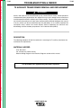
INVERTEC POWER WAVE 450
For use with machines having Code Numbers:
10105 thru 10610
Return to Master TOC
View Safety Info
View Safety Info
Safety Depends on You
Return to Master TOC
Return to Master TOC
RETURN TO MAIN INDEX
Lincoln arc welding and cutting
equipment is designed and
built with safety in mind.
However, your overall safety
can be increased by proper
installation . . . and thoughtful
operation on your part. DO
NOT INSTALL, OPERATE OR
REPAIR THIS EQUIPMENT
WITHOUT READING THIS
MANUAL AND THE SAFETY
PRECAUTIONS CONTAINED
THROUGHOUT. And, most
importantly, think before you
act and be careful.
View Safety Info
Return to Master TOC
SERVICE MANUAL
Copyright © 2001 Lincoln Global Inc.
• World's Leader in Welding and Cutting Products •
• Sales and Service through Subsidiaries and Distributors Worldwide •
Cleveland, Ohio 44117-1199 U.S.A. TEL: 216.481.8100 FAX: 216.486.1751 WEB SITE: www.lincolnelectric.com
Return to Master TOC
i
i
SAFETY
WARNING
CALIFORNIA PROPOSITION 65 WARNINGS
Diesel engine exhaust and some of its constituents
are known to the State of California to cause cancer, birth defects, and other reproductive harm.
The Above For Diesel Engines
The engine exhaust from this product contains
chemicals known to the State of California to cause
cancer, birth defects, or other reproductive harm.
The Above For Gasoline Engines
ARC WELDING CAN BE HAZARDOUS. PROTECT YOURSELF AND OTHERS FROM POSSIBLE SERIOUS INJURY OR DEATH.
KEEP CHILDREN AWAY. PACEMAKER WEARERS SHOULD CONSULT WITH THEIR DOCTOR BEFORE OPERATING.
Return to Master TOC
Return to Master TOC
Return to Master TOC
Read and understand the following safety highlights. For additional safety information, it is strongly recommended that you
purchase a copy of “Safety in Welding & Cutting - ANSI Standard Z49.1” from the American Welding Society, P.O. Box 351040,
Miami, Florida 33135 or CSA Standard W117.2-1974. A Free copy of “Arc Welding Safety” booklet E205 is available from the
Lincoln Electric Company, 22801 St. Clair Avenue, Cleveland, Ohio 44117-1199.
BE SURE THAT ALL INSTALLATION, OPERATION, MAINTENANCE AND REPAIR PROCEDURES ARE
PERFORMED ONLY BY QUALIFIED INDIVIDUALS.
FOR ENGINE
powered equipment.
1.h. To avoid scalding, do not remove the
radiator pressure cap when the engine is
hot.
1.a. Turn the engine off before troubleshooting and maintenance
work unless the maintenance work requires it to be running.
____________________________________________________
1.b. Operate engines in open, well-ventilated
areas or vent the engine exhaust fumes
outdoors.
____________________________________________________
1.c. Do not add the fuel near an open flame welding arc or when the engine is running. Stop
the engine and allow it to cool before refueling to prevent spilled fuel from vaporizing on
contact with hot engine parts and igniting. Do
not spill fuel when filling tank. If fuel is spilled,
wipe it up and do not start engine until fumes
have been eliminated.
____________________________________________________
1.d. Keep all equipment safety guards, covers and devices in position and in good repair.Keep hands, hair, clothing and tools
away from V-belts, gears, fans and all other moving parts
when starting, operating or repairing equipment.
____________________________________________________
1.e. In some cases it may be necessary to remove safety
guards to perform required maintenance. Remove
guards only when necessary and replace them when the
maintenance requiring their removal is complete.
Always use the greatest care when working near moving
parts.
___________________________________________________
1.f. Do not put your hands near the engine fan.
Do not attempt to override the governor or
idler by pushing on the throttle control rods
while the engine is running.
ELECTRIC AND
MAGNETIC FIELDS
may be dangerous
2.a. Electric current flowing through any conductor causes
localized Electric and Magnetic Fields (EMF). Welding
current creates EMF fields around welding cables and
welding machines
2.b. EMF fields may interfere with some pacemakers, and
welders having a pacemaker should consult their physician
before welding.
2.c. Exposure to EMF fields in welding may have other health
effects which are now not known.
2.d. All welders should use the following procedures in order to
minimize exposure to EMF fields from the welding circuit:
2.d.1. Route the electrode and work cables together - Secure
them with tape when possible.
2.d.2. Never coil the electrode lead around your body.
2.d.3. Do not place your body between the electrode and
work cables. If the electrode cable is on your right
side, the work cable should also be on your right side.
2.d.4. Connect the work cable to the workpiece as close as
possible to the area being welded.
___________________________________________________
1.g. To prevent accidentally starting gasoline engines while
turning the engine or welding generator during maintenance
work, disconnect the spark plug wires, distributor cap or
magneto wire as appropriate.
2.d.5. Do not work next to welding power source.
Mar ‘95
Return to Master TOC
Return to Master TOC
ii
ELECTRIC SHOCK can kill.
ARC RAYS can burn.
3.a. The electrode and work (or ground) circuits
are electrically “hot” when the welder is on.
Do not touch these “hot” parts with your bare
skin or wet clothing. Wear dry, hole-free
gloves to insulate hands.
4.a. Use a shield with the proper filter and cover
plates to protect your eyes from sparks and
the rays of the arc when welding or observing
open arc welding. Headshield and filter lens
should conform to ANSI Z87. I standards.
3.b. Insulate yourself from work and ground using dry insulation.
Make certain the insulation is large enough to cover your full
area of physical contact with work and ground.
4.b. Use suitable clothing made from durable flame-resistant
material to protect your skin and that of your helpers from
the arc rays.
In addition to the normal safety precautions, if welding
must be performed under electrically hazardous
conditions (in damp locations or while wearing wet
clothing; on metal structures such as floors, gratings or
scaffolds; when in cramped positions such as sitting,
kneeling or lying, if there is a high risk of unavoidable or
accidental contact with the workpiece or ground) use
the following equipment:
• Semiautomatic DC Constant Voltage (Wire) Welder.
• DC Manual (Stick) Welder.
• AC Welder with Reduced Voltage Control.
4.c. Protect other nearby personnel with suitable, non-flammable
screening and/or warn them not to watch the arc nor expose
themselves to the arc rays or to hot spatter or metal.
3.c. In semiautomatic or automatic wire welding, the electrode,
electrode reel, welding head, nozzle or semiautomatic
welding gun are also electrically “hot”.
3.d. Always be sure the work cable makes a good electrical
connection with the metal being welded. The connection
should be as close as possible to the area being welded.
3.e. Ground the work or metal to be welded to a good electrical
(earth) ground.
3.f. Maintain the electrode holder, work clamp, welding cable and
welding machine in good, safe operating condition. Replace
damaged insulation.
Return to Master TOC
ii
SAFETY
3.g. Never dip the electrode in water for cooling.
3.h. Never simultaneously touch electrically “hot” parts of
electrode holders connected to two welders because voltage
between the two can be the total of the open circuit voltage
of both welders.
3.i. When working above floor level, use a safety belt to protect
yourself from a fall should you get a shock.
3.j. Also see Items 6.c. and 8.
FUMES AND GASES
can be dangerous.
5.a. Welding may produce fumes and gases
hazardous to health. Avoid breathing these
fumes and gases.When welding, keep
your head out of the fume. Use enough
ventilation and/or exhaust at the arc to keep
fumes and gases away from the breathing zone. When
welding with electrodes which require special
ventilation such as stainless or hard facing (see
instructions on container or MSDS) or on lead or
cadmium plated steel and other metals or coatings
which produce highly toxic fumes, keep exposure as
low as possible and below Threshold Limit Values (TLV)
using local exhaust or mechanical ventilation. In
confined spaces or in some circumstances, outdoors, a
respirator may be required. Additional precautions are
also required when welding on galvanized steel.
5.b. Do not weld in locations near chlorinated hydrocarbon vapors
coming from degreasing, cleaning or spraying operations.
The heat and rays of the arc can react with solvent vapors to
form phosgene, a highly toxic gas, and other irritating products.
5.c. Shielding gases used for arc welding can displace air and
cause injury or death. Always use enough ventilation,
especially in confined areas, to insure breathing air is safe.
5.d. Read and understand the manufacturer’s instructions for this
equipment and the consumables to be used, including the
material safety data sheet (MSDS) and follow your
employer’s safety practices. MSDS forms are available from
your welding distributor or from the manufacturer.
5.e. Also see item 1.b.
Return to Master TOC
Mar ‘95
Return to Master TOC
iii
WELDING SPARKS can
cause fire or explosion.
6.a. Remove fire hazards from the welding area.
If this is not possible, cover them to prevent
the welding sparks from starting a fire.
Remember that welding sparks and hot
materials from welding can easily go through small cracks
and openings to adjacent areas. Avoid welding near
hydraulic lines. Have a fire extinguisher readily available.
6.b. Where compressed gases are to be used at the job site,
special precautions should be used to prevent hazardous
situations. Refer to “Safety in Welding and Cutting” (ANSI
Standard Z49.1) and the operating information for the
equipment being used.
Return to Master TOC
6.c. When not welding, make certain no part of the electrode
circuit is touching the work or ground. Accidental contact can
cause overheating and create a fire hazard.
6.d. Do not heat, cut or weld tanks, drums or containers until the
proper steps have been taken to insure that such procedures
will not cause flammable or toxic vapors from substances
inside. They can cause an explosion even though they have
been “cleaned”. For information, purchase “Recommended
Safe Practices for the Preparation for Welding and Cutting of
Containers and Piping That Have Held Hazardous
Substances”, AWS F4.1 from the American Welding Society
(see address above).
6.e. Vent hollow castings or containers before heating, cutting or
welding. They may explode.
6.f. Sparks and spatter are thrown from the welding arc. Wear oil
free protective garments such as leather gloves, heavy shirt,
cuffless trousers, high shoes and a cap over your hair. Wear
ear plugs when welding out of position or in confined places.
Always wear safety glasses with side shields when in a
welding area.
Return to Master TOC
iii
SAFETY
6.g. Connect the work cable to the work as close to the welding
area as practical. Work cables connected to the building
framework or other locations away from the welding area
increase the possibility of the welding current passing
through lifting chains, crane cables or other alternate circuits.
This can create fire hazards or overheat lifting chains or
cables until they fail.
6.h. Also see item 1.c.
CYLINDER may explode
if damaged.
7.a. Use only compressed gas cylinders
containing the correct shielding gas for the
process used and properly operating
regulators designed for the gas and
pressure used. All hoses, fittings, etc. should be suitable for
the application and maintained in good condition.
7.b. Always keep cylinders in an upright position securely
chained to an undercarriage or fixed support.
7.c. Cylinders should be located:
• Away from areas where they may be struck or subjected to
physical damage.
• A safe distance from arc welding or cutting operations and
any other source of heat, sparks, or flame.
7.d. Never allow the electrode, electrode holder or any other
electrically “hot” parts to touch a cylinder.
7.e. Keep your head and face away from the cylinder valve outlet
when opening the cylinder valve.
7.f. Valve protection caps should always be in place and hand
tight except when the cylinder is in use or connected for
use.
7.g. Read and follow the instructions on compressed gas
cylinders, associated equipment, and CGA publication P-l,
“Precautions for Safe Handling of Compressed Gases in
Cylinders,” available from the Compressed Gas Association
1235 Jefferson Davis Highway, Arlington, VA 22202.
FOR ELECTRICALLY
powered equipment.
8.a. Turn off input power using the disconnect
switch at the fuse box before working on
the equipment.
8.b. Install equipment in accordance with the U.S. National
Electrical Code, all local codes and the manufacturer’s
recommendations.
8.c. Ground the equipment in accordance with the U.S. National
Electrical Code and the manufacturer’s recommendations.
Return to Master TOC
Mar ‘95
Return to Master TOC
Return to Master TOC
Return to Master TOC
Return to Master TOC
iv
iv
SAFETY
PRÉCAUTIONS DE SÛRETÉ
6. Eloigner les matériaux inflammables ou les recouvrir afin de
prévenir tout risque d’incendie dû aux étincelles.
Pour votre propre protection lire et observer toutes les instructions
et les précautions de sûreté specifiques qui parraissent dans ce
manuel aussi bien que les précautions de sûreté générales suivantes:
7. Quand on ne soude pas, poser la pince à une endroit isolé de
la masse. Un court-circuit accidental peut provoquer un
échauffement et un risque d’incendie.
Sûreté Pour Soudage A L’Arc
1. Protegez-vous contre la secousse électrique:
a. Les circuits à l’électrode et à la piéce sont sous tension
quand la machine à souder est en marche. Eviter toujours
tout contact entre les parties sous tension et la peau nue
ou les vétements mouillés. Porter des gants secs et sans
trous pour isoler les mains.
b. Faire trés attention de bien s’isoler de la masse quand on
soude dans des endroits humides, ou sur un plancher metallique ou des grilles metalliques, principalement dans
les positions assis ou couché pour lesquelles une grande
partie du corps peut être en contact avec la masse.
c. Maintenir le porte-électrode, la pince de masse, le câble de
soudage et la machine à souder en bon et sûr état defonctionnement.
d.Ne jamais plonger le porte-électrode dans l’eau pour le
refroidir.
e. Ne jamais toucher simultanément les parties sous tension
des porte-électrodes connectés à deux machines à souder
parce que la tension entre les deux pinces peut être le total
de la tension à vide des deux machines.
f. Si on utilise la machine à souder comme une source de
courant pour soudage semi-automatique, ces precautions
pour le porte-électrode s’applicuent aussi au pistolet de
soudage.
2. Dans le cas de travail au dessus du niveau du sol, se protéger
contre les chutes dans le cas ou on recoit un choc. Ne jamais
enrouler le câble-électrode autour de n’importe quelle partie du
corps.
8. S’assurer que la masse est connectée le plus prés possible de
la zone de travail qu’il est pratique de le faire. Si on place la
masse sur la charpente de la construction ou d’autres endroits
éloignés de la zone de travail, on augmente le risque de voir
passer le courant de soudage par les chaines de levage,
câbles de grue, ou autres circuits. Cela peut provoquer des
risques d’incendie ou d’echauffement des chaines et des
câbles jusqu’à ce qu’ils se rompent.
9. Assurer une ventilation suffisante dans la zone de soudage.
Ceci est particuliérement important pour le soudage de tôles
galvanisées plombées, ou cadmiées ou tout autre métal qui
produit des fumeés toxiques.
10. Ne pas souder en présence de vapeurs de chlore provenant
d’opérations de dégraissage, nettoyage ou pistolage. La
chaleur ou les rayons de l’arc peuvent réagir avec les vapeurs
du solvant pour produire du phosgéne (gas fortement toxique)
ou autres produits irritants.
11. Pour obtenir de plus amples renseignements sur la sûreté, voir
le code “Code for safety in welding and cutting” CSA Standard
W 117.2-1974.
PRÉCAUTIONS DE SÛRETÉ POUR
LES MACHINES À SOUDER À
TRANSFORMATEUR ET À
REDRESSEUR
3. Un coup d’arc peut être plus sévère qu’un coup de soliel, donc:
a. Utiliser un bon masque avec un verre filtrant approprié ainsi
qu’un verre blanc afin de se protéger les yeux du rayonnement de l’arc et des projections quand on soude ou
quand on regarde l’arc.
b. Porter des vêtements convenables afin de protéger la peau
de soudeur et des aides contre le rayonnement de l‘arc.
c. Protéger l’autre personnel travaillant à proximité au
soudage à l’aide d’écrans appropriés et non-inflammables.
4. Des gouttes de laitier en fusion sont émises de l’arc de
soudage. Se protéger avec des vêtements de protection libres
de l’huile, tels que les gants en cuir, chemise épaisse, pantalons sans revers, et chaussures montantes.
1. Relier à la terre le chassis du poste conformement au code de
l’électricité et aux recommendations du fabricant. Le dispositif
de montage ou la piece à souder doit être branché à une
bonne mise à la terre.
2. Autant que possible, I’installation et l’entretien du poste seront
effectués par un électricien qualifié.
3. Avant de faires des travaux à l’interieur de poste, la debrancher à l’interrupteur à la boite de fusibles.
4. Garder tous les couvercles et dispositifs de sûreté à leur place.
5. Toujours porter des lunettes de sécurité dans la zone de
soudage. Utiliser des lunettes avec écrans lateraux dans les
zones où l’on pique le laitier.
Mar. ‘93
v
v
RETURN TO MAIN INDEX
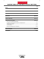
MASTER TABLE OF CONTENTS FOR ALL SECTIONS
Page
Safety.................................................................................................................................................i-iv
Installation .............................................................................................................................Section A
Operation...............................................................................................................................Section B
Accessories...........................................................................................................................Section C
Maintenance .........................................................................................................................Section D
Theory of Operation .............................................................................................................Section E
Troubleshooting and Repair.................................................................................................Section F
How To Use Troubleshooting Guide ...........................................................................................F-2
PC Board Troubleshooting Procedures and Replacement.........................................................F-3
Troubleshooting Guide ................................................................................................................F-5
Test Procedures ........................................................................................................................F-27
Removal and Replacement Procedures .................................................................................F-155
Electrical Diagrams ..............................................................................................................Section G
Parts Manual................................................................................................................................P-261
POWER WAVE 450
Return to Master TOC
Section A-1
TABLE OF CONTENTS
- INSTALLATION SECTION -
Section A-1
Installation
Technical Specifications .............................................................................................................A-2
Safety Precautions......................................................................................................................A-3
Select Suitable Location .............................................................................................................A-3
Stacking................................................................................................................................A-3
Tilting .................................................................................................................................A-3
Lifting .................................................................................................................................A-3
High Frequency Precautions.......................................................................................................A-3
Return to Master TOC
Input Connections.......................................................................................................................A-3
Ground Connections...................................................................................................................A-4
Input Power Connections ...........................................................................................................A-4
Input Fuse and Supply Wire Considerations .......................................................................A-4
Input Voltage Reconnect Procedure ....................................................................................A-4
Output Connections....................................................................................................................A-5
Work and Electrode Cable Connections ..............................................................................A-5
Size.................................................................................................................................A-5
Routing............. ..............................................................................................................A-5
Water Cooler Connections ...................................................................................................A-5
Return to Master TOC
Return to Master TOC
Wire Feeder Connections.....................................................................................................A-5
POWER WAVE 450
Return to Master TOC
Return to Section TOC
A-2
A-2
INSTALLATION
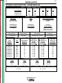
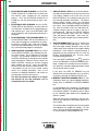
TECHNICAL SPECIFICATIONS - POWER WAVE 450
INPUT -THREE PHASE ONLY
Input Voltages:
200
230
400
460
575
Input Currents
@ 500A/40 VDC
@ 450A/38 VDC
87
75
76
65
44
38
38
32
32
28
Return to Master TOC
Return to Section TOC
RATED OUTPUT
Duty Cycle
Amps
Volts at Rated Amperes
60% Duty Cycle
100% Duty Cycle
500
450
40 VDC
38 VDC
Constant Open
Circuit Voltage
Continuous
Current Range
Process
Current Ranges
75 Volts
5-540 Amps
GMAW 50-540 Amps
FCAW 40-540 Amps
STICK 30-540 Amps
Pulse
Current Range
Pulse
Voltage Range
Pulse and Background
Time Range
Pulse
Frequency
5-750 Amps
5-55 Volts
100 Microsec - 3.3 Sec
0.15 - 1000 Hz
Return to Master TOC
Return to Section TOC
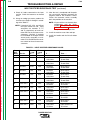
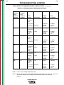
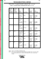
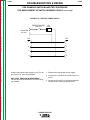
RECOMMENDED INPUT WIRE AND FUSE SIZES
Input
Voltage/
Freqency
Duty
Cycle
Input Ampere
Rating on
Nameplate
200/50-60
230/50-60
400/50-60
460/50-60
575/50-60
200/50-60
230/50-60
400/50-60
460/50-60
575/50-60
60%
60%
60%
60%
60%
100%
100%
100%
100%
100%
87
76
44
38
32
75
65
38
32
28
Type 75°C
Copper Wire in
Conduit
AWG[IEC]
Sizes (MM2)
4
4
8
8
8
4
4
8
8
8
Type 75°C
Ground Wire in
Conduit
AWG[IEC]
Sizes (MM2)
Type 75°C
(Super Lag)
or Breaker
Size (Amps)
8 (10)
8 (10)
10 (6)
10 (6)
10 (6)
8 (10)
8 (10)
10 (6)
10 (6)
10 (6)
120
100
50
50
50
100
100
50
50
40
(25)
(25)
(10)
(10)
(10)
(25)
(25)
(10)
(10)
(10)
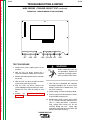
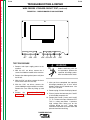
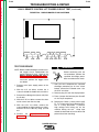
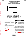
Height
Width
Depth
Weight
905 mm
35.6 in.
515 mm
20.3 in.
1010 mm
39.8 in.
137.9 kg
303.5 lbs.
OPERATING TEMPERATURE RANGE STORAGE TEMPERATURE RANGE
Return to Master TOC
Return to Section TOC
PHYSICAL DIMENSION
0° to 40°C
-50° to 85°C
POWER WAVE 450
Return to Master TOC
Return to Section TOC
A-3
INSTALLATION
Read this entire installation section before you
start installation.
LIFTING
SAFETY PRECAUTIONS
HIGH FREQUENCY PRECAUTIONS
WARNING
ELECTRIC SHOCK can kill.
• Only qualified personnel should
perform this installation.
Return to Master TOC
Return to Master TOC
Return to Section TOC
Return to Section TOC
• Turn the input power OFF at the
disconnect switch or fuse box
before working on this equipment.
• Do not touch electrically hot parts.
• Always connect the Power Wave grounding terminal
(located inside the reconnect input access doors).
Lift the machine by the lift bail only. Do not attempt to
lift the machine by the push handle.
If possible, locate the Power Wave away from radio
controlled machinery. The normal operation of the
Power Wave may adversely affect the operation of RF
controlled equipment, which may result in bodily injury
or damage to the equipment.
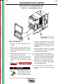
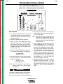
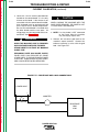
INPUT CONNECTIONS
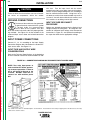
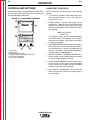
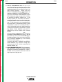
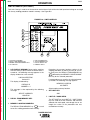
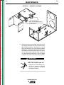
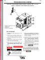
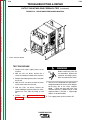
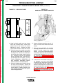
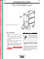
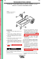
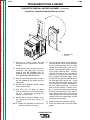
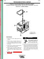
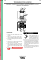
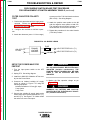
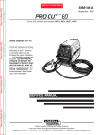
Be sure the voltage, phase, and frequency of the input
power is as specified on the rating plate, located on
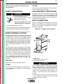
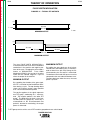
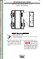
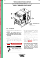
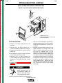
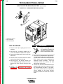
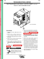
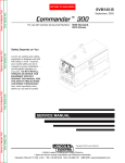
the rear of the machine. See Figure A.1 for the location of the rating plate.
FIGURE A.1 - RATING PLATE LOCATION
SELECT SUITABLE LOCATION
Place the welder where clean cooling air can circulate
in through the rear louvers and out through the side
and front louvers. Dirt, dust, or any foreign material
that can be drawn into the welder should be kept at a
minimum. Using filters on the air intake to prevent dirt
from building up restricts air flow. Do not use such filters. Failure to observe these precautions can result in
excessive operating temperatures and nuisance shutdowns.
The Power Wave may be used outdoors. Power Wave
power sources carry an IP23 enclosure rating. They
are rated for use in damp, dirty environments subject
to occasional falling water such as rain. However, the
best practice is to keep the machine in a dry, sheltered
area, since a wet environment speeds corrosion of
parts. Do not place the machine in puddles or otherwise submerge parts of the machine in water. This
may cause improper operation and is a possible safety hazard.
STACKING
3
1. RATING PLATE
2. RECONNECT/INPUT ACCESS DOOR
3. INPUT CORD ACCESS HOLE
WARNING
TILTING
Return to Master TOC
2
1
Power Wave machines cannot be stacked.
Return to Section TOC
A-3
Each machine must be placed on a secure, level surface. The machine may topple over if this procedure
is not followed.
Only a qualified electrician should connect the input
leads to the Power Wave. Connections should be
made in accordance with all local and national electrical codes and the connection diagram located on the
inside of the reconnect/input access door of the
machine. Failure to do so may result in bodily injury
or death.
Use a three-phase supply line. The Power Wave has
a 1.375” (35mm) access hole for the input cord, but
the input cord is not supplied.
POWER WAVE 450
Return to Master TOC
Return to Master TOC
Return to Section TOC
Return to Section TOC
A-4
A-4
INSTALLATION
CAUTION
Failure to follow these instructions can cause immediate failure of components within the welder.
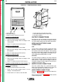
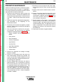
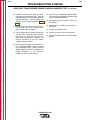
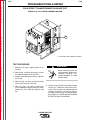
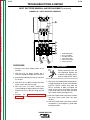
GROUND CONNECTIONS
The frame of the welder must be grounded.
A ground terminal marked with the symbol
is located inside the reconnect/input
access door for this purpose. See your
local and national electrical codes for proper grounding methods. See Figure A.2 for the location of the
reconnect/input access door and related connection
diagram.
wire sizes. Fuse the input circuit with the recommended super lag fuses or delay type circuit breakers.
Choose an input and grounding wire size according to
local or national electrical codes. Using fuses or circuit breakers smaller than recommended may result in
“nuisance” shut-offs from welder inrush currents, even
if the machine is not being used at high currents.
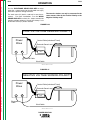
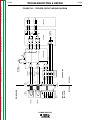
INPUT VOLTAGE RECONNECT
PROCEDURE
Welders are shipped connected for the highest input
voltage listed on the rating plate. To change this connection for a different input voltage, refer to reconnect
instructions in Figure A.2 and proceed according to
the steps that follow for the appropriate voltage.
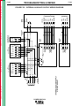
INPUT POWER CONNECTIONS
Connect L1, L2, L3 according to the Input Supply
Connection Diagram decal located on the reconnect/input access door. See Figure A.2.
INPUT FUSE AND SUPPLY WIRE
CONSIDERATIONS
Refer to the Technical Specifications at the beginning
of this Installation section for recommended fuse and
Return to Section TOC
Return to Master TOC
Return to Master TOC
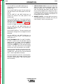
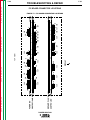
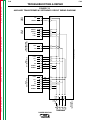
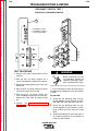
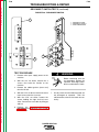
NOTE: Turn main input power to
mthe machine OFF before performing reconnect procedure. Failure to
do so will result in damage to the
machine. DO NOT switch the reconnect bar with machine power
ON.
LY R
N
M
O OU A
E Y GR
PL O A
M R T DI
SA FE FIC
E I
R EC
SP
Return to Section TOC
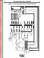
FIGURE A.2 - CONNECTION DIAGRAM ON RECONNECT/INPUT ACCESS DOOR
Also called “inverse time” or “thermal/magnetic” circuit breakers. These breakers have a delay in tripping action that decreases as the magnitude of the current increases.
POWER WAVE 450
A-5
INSTALLATION
Return to Master TOC
Return to Section TOC
A-5
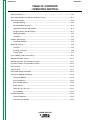
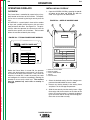
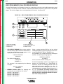
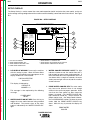
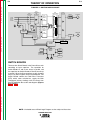
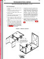
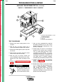
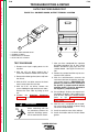
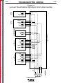
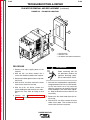
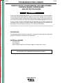
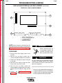
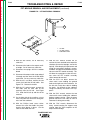
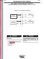
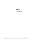
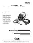
FIGURE A.3 – FRONTPANEL/BACK PANEL
6
5
(IN)
4
Return to Master TOC
Return to Section TOC
(OUT)
1
3
2
1 WORK TERMINAL
2 ELECTRODE TERMINAL
3 REMOTE CONTROL AMPHENOL RECEPTACLE
4 WATER COOLING FITTINGS (ON BACK PANEL)
5 WIRE FEEDER CONNECTIONS (ON BACK PANEL)
6 ELECTRODE TERMINAL
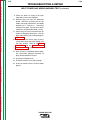
To operate at 200-208 VAC:
OUTPUT CONNECTIONS
1. Open the reconnect/input access door.
See Figure A.3 for the location of the work terminal,
electrode terminal, remote control amphenol receptacle, water cooler fittings and wire feeder connections.
2. Move the input voltage switch to Voltage = 200208V position.
Return to Master TOC
Return to Section TOC
3. Move “A” lead to the 200-208V terminal.
To operate at 220-230 VAC:
SIZE
1. Open the reconnect/input access door.
To operate at 380-415 VAC:
Use the largest welding (electrode and ground) cables
possible — at least 70mm2 (#2/0) copper wire — even
if the output current does not require it. When pulsing,
the pulse current often exceeds 650 amps with the
Power Wave 450. Voltage drops can become excessive if undersized welding cables are used.
1. Open the reconnect/input access door.
ROUTING
2. Move the input voltage switch to Voltage = 380415V position.
To avoid interference problems with other equipment
and to achieve the best possible operation, route all
cables directly. Avoid excessive lengths, bundle the
electrode and ground cables together where practical,
and do not coil excess cable.
2. Move the input voltage switch to voltage = 220230V position.
3. Move “A” lead to the 220-230V terminal.
Return to Master TOC
3. Move “A” lead to the 380-415 VAC terminal.
Return to Section TOC
WORK AND ELECTRODE CABLE
CONNECTIONS
To operate at 440-460 VAC: No setup required. The
machine is factory-connected to operate at 440 volts.
To verify, do the following:
1. Open the reconnect/input access door.
WATER COOLER CONNECTIONS
The water cooler fittings are a quick-connect type.
Refer to the Accessories section of this manual for
water cooler operation and antifreeze mixtures.
2. Check that the input voltage switch is set to
Voltage = 440-460V position.
WIRE FEEDER CONNECTIONS
3. Check that the “A” lead is at the 440-460V.
Refer to the Accessories section for Wire Feeder Connections.
Refer to Setup overlay in Operation section for Wire
Feeder Configuration.
POWER WAVE 450
Return to Section TOC
Return to Master TOC
Return to Section TOC
Return to Master TOC
Return to Master TOC
Return to Section TOC
Return to Master TOC
Return to Section TOC
NOTES
POWER WAVE 450
Return to Master TOC
Section B-1
Section B-1
TABLE OF CONTENTS
- OPERATION SECTION Operation...............................................................................................................................Section B
Safety Instructions ......................................................................................................................B-2
Quick Start Reference for Process Selection Overlay................................................................B-3
General Description ....................................................................................................................B-4
Synergic Welding..................................................................................................................B-4
Recommended Processes ...................................................................................................B-4
Operational Features and Controls ......................................................................................B-4
Design Features and Advantages ........................................................................................B-4
Return to Master TOC
Welding Capability................................................................................................................B-4
Limitations ............................................................................................................................B-4
Controls and Settings .................................................................................................................B-5
Case Front Controls .............................................................................................................B-5
Operating Overlays .....................................................................................................................B-6
Overview...............................................................................................................................B-6
Installing an Overlay .............................................................................................................B-6
Overlay Types .......................................................................................................................B-7
Pulse, GMAW, FCAW, Stick Overlay ..........................................................................................B-8
Weld from Memory Overlay ......................................................................................................B-11
Weld from Memory, Dual Procedure Overlay ...........................................................................B-12
Return to Master TOC
Dual Wire Feeders, Dual Procedure Overlay ............................................................................B-14
Limits Overlay ...........................................................................................................................B-15
Setup Overlay ...........................................................................................................................B-17
Wire Feeder Setup Description ................................................................................................B-18
Overview of Welding Procedures .............................................................................................B-20
FCAW and GMAW..............................................................................................................B-20
Pulse Procedures ...............................................................................................................B-20
Stick/TIG Procedures .........................................................................................................B-20
Wave Control......................................................................................................................B-20
Tables B.3, B.4, B.5, B.6 ....................................................................................................B-21
Pulse Welding.....................................................................................................................B-22
Return to Master TOC
Overload Protection..................................................................................................................B-23
Thermal Protection .............................................................................................................B-23
Over Current Protection .....................................................................................................B-23
POWER WAVE 450
Return to Master TOC
Return to Section TOC
B-2
OPERATION
OPERATING INSTRUCTIONS
Read and understand this entire section of operating
instructions before operating the machine.
SAFETY INSTRUCTIONS
WARNING
ELECTRIC SHOCK can kill.
Return to Master TOC
Return to Section TOC
• Do not touch electrically live parts or
electrodes with your skin or wet clothing.
• Insulate yourself from the work and ground.
• Always wear dry insulating gloves.
FUMES AND GASES can be
dangerous.
• Keep your head out of fumes.
• Use ventilation or exhaust to remove
fumes from breathing zone.
Return to Master TOC
Return to Section TOC
WELDING SPARKS can cause
fire or explosion.
• Keep flammable material away.
• Do not weld on containers that have held combustibles.
ARC RAYS can burn.
• Wear eye, ear, and body protection.
Observe additional Safety Guidelines
detailed in the beginning of this manual.
Return to Master TOC
Return to Section TOC
HOT COOLANT can burn skin.
• Always be sure coolant is not hot before
doing any work on cooler parts.
POWER WAVE 450
B-2
Return to Master TOC
Return to Section TOC
B-3
OPERATION
QUICK START REFERENCE FOR
USING THE PROCESS SELECTION
OVERLAY
Step 2: Adjust the wire feed to speed “WFS” and
voltage “V” or arc length “T” (if necessary).
a. Press the DISPLAY RECALL key
view additional procedure information.
Read and understand the “Controls and Settings” and
“Operating Overlays” sections of this manual before
using the following Quick Start Reference procedure
to operate the Power Wave.
NOTE: Selection of certain options may limit the
selection of subsequent options.
Step 3: Save process information (if desired).
a. Press the SAVE TO MEMORY key
a. Install the desired PROCESS OVERLAY.
Return to Master TOC
Return to Master TOC
Return to Section TOC
Return to Section TOC
.
You can recall your procedure later by pressing the
RECALL FROM MEMORY key
RECALL
and the appro-
priate MEMORY LOCATION key.
1
The electrode class, electrode size, and electrode/
gas type you can select for your process will be
limited to the machine’s programmed recommendations. Therefore, selecting certain options may limit
other option selections.
2
The wave control scale displayed shows the default
setting. (The higher the setting, the softer the arc.) If
you change the setting, your new setting will be displayed.
d. Select ELECTRODE CLASS.
e. Select ELECTRODE SIZE.
f.
Return to Master TOC
SAVE
b. Press one of the MEMORY LOCATION keys
(1-8).
b. Turn the machine ON.
c. Select the desired welding
PROCESS1.
to
b. Adjust wire feed speed and voltage or arc
length trim through the controls on your wire
feeder. The new values appear on both the
wire feeder and the Power Wave display.
Step 1: Select your process information:
Return to Section TOC
B-3
Select ELECTRODE/GAS TYPE.
g. Press the WAVE CONTROL
UP or DOWN keys to see
the present setting. Press
the WAVE CONTROL UP or
WAVE CONTROL DOWN
keys to adjust2.
POWER WAVE 450
Return to Master TOC
Return to Master TOC
Return to Section TOC
Return to Section TOC
B-4
OPERATION
GENERAL DESCRIPTION
DESIGN FEATURES AND ADVANTAGES
The INVERTEC Power Wave power source is a high
performance, digitally controlled inverter welding
power source capable of complex, high-speed waveform control. It uses three-phase input power only.
The Power Wave is designed to be used as a synergic
welding system in conjunction with a wire feeder.
• Designed to NEMA Standards.
SYNERGIC WELDING
• Modular construction for easy servicing.
The Power Wave system is designed primarily as a
synergic welding system. The word “synergic” comes
from the word “synergism,” which means “two or more
things working together to achieve an effect which neither can achieve individually.”
• Thermostatically protected.
The Power Wave and wire feeder operate as a team.
Each “knows” what the other is doing at all times.
They each also know what process, wire type, wire
size, and gas combination are being used. In a synergic system, the wire feeder and power source must
“talk” together. This means that only certain wire feeders can work in a synergic setup. A synergic feeder
has special circuitry to “talk” with and “listen” to the
Power Wave power source.
Return to Master TOC
Return to Section TOC
Welding experts have preprogrammed the system for
the best range of process settings according to wire
type, wire size, and gas combination. When the wire
feed speed is changed, the system automatically
adjusts the current and voltage waveforms to give the
best weld characteristics. This improves the soundness, appearance, and repeatability of welds.
Refer to the Accessories section of this manual for
available wire feeders.
RECOMMENDED PROCESSES
The Power Wave is designed to be used as a multiple
process machine. It comes preprogrammed with
GMAW pulse, GMAW (short arc and spray) FCAW
(Innershield™ and Outershield™), and stick procedures.
Return to Master TOC
OPERATIONAL FEATURES AND
CONTROLS
Return to Section TOC
B-4
The Power Wave, through use of a keypad overlay
system, provides various options and controls such as
Multiple Process/Procedure Selection; Memory
Storage of Procedures; Weld from Memory Only operation; Dual Process/Dual Feeder capability.
• Multiple process output ranges 5 - 540 amps.
• 2-line LCD display.
• Easy access for input connections. Connections
are simple strip and clamp (no lugs required).
• Electronic overcurrent protection.
• Overvoltage protection.
• Digital signal processor and microprocessor control.
• RS232 interface for future welding application
updates.
• Simple, reliable reconnection for various input voltages.
• New accessories and wire feeders communicate
using a digital current loop to transfer information.
• Auto device recognition simplifies accessory cable
connections.
• Direct support of two wire feeders.
• Auto-configurable for either metric or English mode.
• Multi-process control: Stick, short arc, GMAW
spray, GMAW pulse, and flux cored arc welding
(FCAW).
• Simple control through use of overlays that limit
access to only those keys required for a given application.
WELDING CAPABILITY
The Power Wave 450 is rated at 500 amps, 40 volts at
60% duty cycle based on a ten minute time period. It
is capable of higher duty cycles at lower output currents. If the duty cycles are exceeded, a thermostat
will shut off the output until the machine cools to a reasonable operating temperature.
LIMITATIONS
• The Power Wave is not recommended for processes other than those specified by available overlays.
• The Power Wave is not recommended for pipe
thawing.
POWER WAVE 450
Return to Master TOC
Return to Section TOC
B-5
B-5
OPERATION
CONTROLS AND SETTINGS
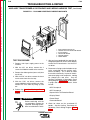
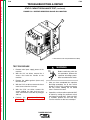
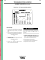
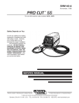
CASE FRONT CONTROLS
All operator controls and adjustments are located on
the case front of the Power Wave. Refer to Figure B.1
and corresponding explanations.
Refer to Figure B.1 for the location of the following
controls:
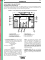
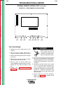
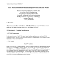
FIGURE B.1 – CASE FRONT CONTROLS
6
3
1
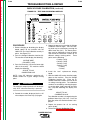
1. LCD DISPLAY: Provides welding procedure information and parameters such as wire type, gas
type, WFS, trim, etc.
2. POWER SWITCH: Controls input power to the
Power Wave. When the switch is turned to the ON
position, the connected wire feeder meters light
up and the LCD display on the Power Wave shows
the following:
Return to Section TOC
Return to Master TOC
Return to Master TOC
Return to Master TOC
2
Return to Section TOC
Return to Section TOC
LINCOLN ELECTRIC
Version X.X
This display is shown for a few seconds followed
by another display that depends on the overlay
placed on the machine. At this point, the machine
is ready for operation.
4
1
2
3
4
5
6
5
LCD DISPLAY
POWER SWITCH
HIGH TEMPERATURE LIGHT
REMOTE CONTROL AMPHENOL RECEPTACLE
5 AMP CIRCUIT BREAKER
LCD DISPLAY ADJUSTMENT
3. HIGH TEMPERATURE LIGHT (thermal overload): A
yellow light that comes on when an over temperature situation occurs. Output is disabled until the
machine cools down. At that point the light goes
out and output is enabled again.
4. REMOTE CONTROL AMPHENOL RECEPTACLE:
Allows remote current control during stick welding
via a hand or foot Amptrol accessory.
5. 5 AMP CIRCUIT BREAKER: Protects two auxiliary
power circuits: the 24V supply used by the trigger
circuits and the 42V supply used by the internal
machine circuits and the wire feeders.
6. LCD DISPLAY ADJUSTMENT: Use a small flat
blade screw driver to adjust the viewing angle of
the LCD display.
POWER WAVE 450
Return to Master TOC
Return to Section TOC
B-6
B-6
OPERATION
OPERATING OVERLAYS
INSTALLING AN OVERLAY
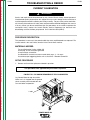
OVERVIEW
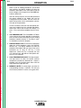
1. Open the ACCESS DOOR by grasping the provided indent on the door and pulling the door forward. See Figure B.3 for door location.
The Power Wave is controlled by a panel of keys (keypad) located on the front of the machine. The operator can access controls by placing an overlay over the
keys.
FIGURE B.3 – OVERLAY ACCESS DOOR
An OVERLAY is a special plastic sheet with a number
of keys and symbols printed on one side and a bar
code printed on the other. See Figure B.2. The printed keys allow the operator to communicate with the
machine for a specific set of functions. The bar code
allows the machine to identify the overlay.
5
3
1
2
Return to Master TOC
Return to Section TOC
4
FIGURE B.2 – TYPICAL POWER WAVE OVERLAY
C COPYRIGHT 1994
L9361-2 WELD FROM MEMORY
™
TM
R
INVERTEC POWER WAVE 350
WARNING
HIGH TEMP.
PROGRAM LIST
MEMORY RECALL
1
M
3
M
M
5
M
6
M
7
M
8
M
Return to Master TOC
M
Return to Section TOC
THE LINCOLN ELECTRIC COMPANY CLEVELAND, OHIO USA
2
4
1
2
3
4
5
6
7
8
DISPLAY
RECALL
Before the Power Wave is turned ON, the operator
selects the desired overlay and mounts it in the overlay frame on the front of the machine. Then, when the
machine is turned ON, it reads the overlay bar code
and configures the machine accordingly, allowing the
operator to access only certain keys. The machine
must be powered up each time an overlay is
changed.
1
2
3
4
5
OVERLAY ACCESS DOOR
OVERLAY FRAME
ACCESS DOOR INDENT
TRACKS
LOCATING PINS
2. Select the desired overlay from the storage compartment located behind the access door.
Return to Master TOC
Return to Section TOC
3. Remove any overlay already in the overlay frame
and place it in the storage compartment.
4. Slide the new overlay into the overlay frame. Align
the overlay with the two tracks on the sides of the
frame. Be sure the overlay is seated in the bottom
lip of the frame and on the top two locating pins.
Close the access door securely.
POWER WAVE 450
Return to Master TOC
Return to Section TOC
B-7
OPERATION
OVERLAY TYPES
Four types of overlays can be used with the Power
Wave.
1. Process Overlays. These overlays are used to
create, save and recall specific welding procedures by selecting and adjusting the various welding settings that have been programmed into the
Power Wave at the factory.
Return to Master TOC
Return to Master TOC
Return to Master TOC
Return to Section TOC
Return to Section TOC
2. Weld From Memory Overlays. These overlays
(also called Shop Overlays) provide a simple way
for operators to recall and use any of the welding
procedures that have been stored in the memory
of the Power Wave.
Return to Section TOC
B-7
3. Setup Overlays. These overlays provide specific
machine setup information, such as operating limits for the welding procedures stored in memory.
Overlay
Type
1
Overlay
Name
Figure
No.
GMAW PULSE, GMAW
FCAW, STICK PROCESS
SELECTION OVERLAY
B.4
WELD FROM MEMORY
OVERLAY
B.5
WELD FROM MEMORY, DUAL
PROCEDURE OVERLAY
B.6
*DUAL WIRE FEEDERS, DUAL
PROCEDURES OVERLAY
B.7
3
*LIMITS OVERLAY
B.8
3
SETUP OVERLAY
B.9
2
2
2
*These overlays are optional. See Accessories
Section for Order Numbers.
4. Special Purpose Overlays. These are custom
overlays for specific customer applications.
Detailed information on how to use currently available
Power Wave overlays follows.
POWER WAVE 450
Return to Master TOC
Return to Master TOC
Return to Section TOC
Return to Section TOC
B-8
OPERATION
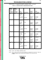
PULSE, GMAW, FCAW, AND STICK/TIG
PROCESS SELECTION OVERLAY
An operator can use this overlay to create a new welding procedure, save a newly created welding procedure,
view an existing welding procedure, recall an existing welding procedure, and clear a memory location. See
Figure B.4. The steps for performing each of these functions are given below.
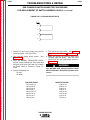
FIGURE B.4 – PULSE, GMAW, FCAW, STICK/TIG PROCESS SELECTION OVERLAY
1
11
10
2
8
6
9
Return to Master TOC
Return to Section TOC
3
1
2
3
4
5
6
4
LCD DISPLAY WINDOW
PROCESS SELECT KEY
ELECTRODE CLASS UP/DOWN KEYS
ELECTRODE SIZE UP/DOWN KEYS
ELECTRODE/GAS TYPE UP/DOWN KEYS
WAVE CONTROL UP/DOWN KEYS
1. LCD DISPLAY WINDOW: Power up the machine
with this overlay in place. When the Power Wave
is turned on, the following message appears on
the display for a few seconds:
LINCOLN ELECTRIC
VERSION X.X
Return to Master TOC
This display is followed by:
Return to Section TOC
B-8
OVERLAY ID
NUMBER = 1
A welding procedure is made up of seven components: process, material type, wire diameter, program,
wire feed speed, voltage or arc length trim, and wave
control. A new welding procedure is created by
selecting a combination of these components from the
ones that have been programmed into the Power
Wave. See Figure B.4 for key locations.
5
7
7
8
9
10
11
DISPLAY RECALL KEY
SAVE TO MEMORY KEY
MEMORY LOCATION NUMBER KEYS
RECALL FROM MEMORY KEY
HIGH TEMPERATURE LIGHT
NOTE: The following four selections should
always be performed in this order: process, electrode class, electrode size, electrode/gas type.
Selecting a setting for one component narrows
your choice of available settings in remaining components. This is why the order of performing the
steps is important. However, if you make component selections out of order, the machine will
prompt you to make a new selection for any settings that do not apply.
2. PROCESS SELECT KEY: Use the PROCESS
SELECT key to select from the processes available in the machine. Press the PROCESS
SELECT key until the light by the desired process
is lit.
POWER WAVE 450
Return to Master TOC
Return to Master TOC
Return to Master TOC
Return to Section TOC
Return to Section TOC
Return to Section TOC
B-9
OPERATION
3. ELECTRODE CLASS UP/DOWN: Use the ELECTRODE CLASS UP or DOWN keys to select from
the material types available for the selected
process. Press the ELECTRODE CLASS UP or
DOWN key until the desired material type is displayed.
4. ELECTRODE SIZE UP/DOWN: Use the ELECTRODE SIZE UP or DOWN keys to select from the
wire diameters available for the selected process
and material type. Press the ELECTRODE SIZE
UP or DOWN key until the desired wire diameter is
displayed.
5. ELECTRODE/GAS TYPE UP/DOWN KEYS: Use
the ELECTRODE/GAS TYPE UP or DOWN keys to
select from the programs available for the selected process, material type, and wire diameter.
Press the ELECTRODE/GAS TYPE UP or DOWN
Key until the desired program is displayed.
6. WAVE CONTROL UP/DOWN KEYS: Press one of
the two WAVE CONTROL keys to display the present wave control. This is shown on a scale from
LO to HI. Use the WAVE CONTROL UP or WAVE
CONTROL DOWN key to change the wave control
to the desired level. When this scale is shown, the
WAVE CONTROL setting can also be changed
while welding (on the fly). Press the DISPLAY
RECALL key to exit the wave control function. For
a description of how the wave control setting
affects the welding procedure, refer to the
Overview of Welding Procedures sub-section of
the Operation section of this manual.
The wire feed speed and voltage or arc length
trim desired for the new procedure can be
changed from the wire feeder.
B-9
7. DISPLAY RECALL KEY: Since not all the information about the procedure can be seen on the 2-line
LCD display window at the same time, use the
DISPLAY RECALL key to display and verify all of
the selected procedure information. The normal
default display window shows the Procedure
Description, WFS, and preset voltage or arc length
trim values. Press and hold the DISPLAY RECALL
key, and the window shows the procedure description and gas type for as long as the key is
held depressed. Release the DISPLAY RECALL
key, and the window shows wire size, material
type, and process description. After a few seconds, the window changes back to the default display.
8. SAVE TO MEMORY KEY: This key is used to save
a newly created welding procedure. The Power
Wave has eight memory locations which can be
used to store all the settings of up to eight welding
procedures. Once stored in a memory location, a
procedure can be recalled for later use with the
RECALL FROM MEMORY key. To save a newly
created welding procedure:
Press the SAVE TO MEMORY key SAVE and then
one of the MEMORY LOCATION NUMBER keys.
Keep a record of this number for future reference.
Any previously created welding procedure stored
in that location will be erased.
If you press the SAVE TO MEMORY key but
decide not to save the procedure, you can exit this
function by pressing the DISPLAY RECALL key.
9. MEMORY LOCATION NUMBER KEYS: To view
information about any stored welding procedure,
simply press its MEMORY LOCATION NUMBER
key.
As you hold down the selected key, the procedure
description and gas type of the procedure appear
in the display window. The process type is shown
by the indicating light opposite the appropriate
process symbol.
Return to Master TOC
Return to Section TOC
When you release the selected key, the wire size,
material type and process description appear for a
few seconds.
This function does not display the wire feed speed
and voltage or arc length trim settings. To view
these, you must recall the procedure from memory with the RECALL FROM MEMORY key.
POWER WAVE 450
B-10
Return to Master TOC
Return to Master TOC
Return to Master TOC
Return to Master TOC
Return to Section TOC
Return to Section TOC
The RECALL FROM MEMORY and SAVE TO
MEMORY keys can be used to clear a memory
location.
Return to Section TOC
10. RECALL FROM MEMORY KEY: This key is used
to recall an existing procedure from memory. You
can recall and use any of the previously created
welding procedures that are stored in one of the
eight memory locations.
Simply press the
RECALL FROM MEMORY key RECALL and then the
appropriate MEMORY LOCATION NUMBER key.
Return to Section TOC
OPERATION
If you press the RECALL FROM MEMORY key and
then change your mind, you can exit this function
by pressing the DISPLAY RECALL key. If the
memory location you select does not contain a
stored welding procedure, this will be indicated in
the display window. Select another memory location. It is not necessary to save a procedure back
to memory after it is recalled from memory. When
a procedure is saved into a memory location, it
can be recalled from there until another procedure
is stored in that location or the location is cleared.
SAVE
Press the SAVE TO MEMORY key
and then
the RECALL FROM MEMORY key RECALL . (Do not
press both keys at the same time.) A message in
the display window will ask you to press the MEMORY LOCATION NUMBER key of the memory
location you want to clear.
If you press the SAVE TO MEMORY and RECALL
FROM MEMORY keys and then change your
mind, you can exit this function by pressing the
DISPLAY RECALL key.
11. HIGH TEMPERATURE LIGHT: The high temperature light comes on when the internal machine
temperature exceeds the allowed limit. Output is
disabled until the machine cools down and the
high temperature light goes out.
POWER WAVE 450
B-10
Return to Master TOC
Return to Section TOC
B-11
B-11
OPERATION
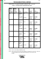
WELD FROM MEMORY OVERLAY
The Weld From Memory Overlay lets an operator recall and use any welding procedure stored in one of eight memory locations. See Figure B.5.
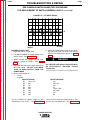
FIGURE B.5 – WELD FROM MEMORY OVERLAY
1
1
2
3
4
5
6
LCD DISPLAY WINDOW
MEMORY RECALL KEYS
PROGRAM LIST
DISPLAY RECALL KEY
HIGH TEMPERATURE LIGHT
MEMORY LIGHTS
5
6
Return to Master TOC
Return to Section TOC
2
3
1. LCD DISPLAY WINDOW: Power up the machine
with this overlay in place. When the Power Wave
is turned on, the following message appears in the
display window for a few seconds:
LINCOLN ELECTRIC
Version X.X
Return to Master TOC
OVERLAY ID
NUMBER = 2
Return to Section TOC
This message is then replaced by the following
message:
SELECT A MEMORY
LOCATION
2. MEMORY RECALL NUMBERS: Select the memory location of the desired welding procedure by
pressing the appropriate MEMORY RECALL
NUMBER key.
If no procedure was saved in the selected memory location, the following message appears:
MEMORY LOCATION
# IS EMPTY
Select another memory location.
Return to Master TOC
With this overlay in place, the wire feed speed and
the preset voltage or arc length trim can be
changed from the wire feeder. The new values will
replace the previous values and become a permanent part of the procedure.
If limits have been set on the wire feed speed, voltage or arc length trim of the selected procedure,
these limits will be active when this overlay is in
place. They cannot be overridden from this overlay.
This display is followed by:
Return to Section TOC
4
When a welding procedure is recalled from memory, the display window will show the procedure
description, wire feed speed, and arc length trim
or preset voltage.
3. PROGRAM LIST: The PROGRAM LIST block in
the center of this overlay provides a convenient
place to record a brief description of each welding
procedure stored in memory. A “Dry Erase” marker should be used for this purpose.
4. DISPLAY RECALL KEY: To view other information
about the selected procedure, press the DISPLAY
RECALL key. The display window will show the
procedure description and gas type of the selected procedure for as long as the key is held
depressed. When the key is released, material
type, wire size, and process descriptions will be
displayed for a few seconds.
5. HIGH TEMPERATURE LIGHT: The high temperature light comes on when the internal machine
temperature exceeds the allowed limit. Output is
disabled until the machine cools down and the
high temperature light goes out.
6. MEMORY LIGHTS: A memory light is on when its
corresponding memory is selected. This tells you
what memory is active at any given time.
POWER WAVE 450
Return to Master TOC
Return to Section TOC
B-12
B-12
OPERATION
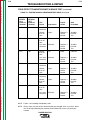
WELD FROM MEMORY, DUAL PROCEDURE OVERLAY
The Weld From Memory, Dual Procedure Overlay lets an operator recall and use dual welding procedures stored
in memory. The overlay must be used with a separate dual procedure switch or a gun that has a two position
trigger. The switch or trigger selects which procedure will be active. See Figure B.6
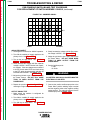
FIGURE B.6 – WELD FROM MEMORY, DUAL PROCEDURE OVERLAY
Return to Master TOC
Return to Section TOC
1
5
6
2
Return to Master TOC
Return to Section TOC
3
1 LCD DISPLAY WINDOW
2 MEMORY RECALL KEYS
3 PROGRAM LIST
4
4 DISPLAY RECALL KEY
5 HIGH TEMPERATURE LIGHT
6 MEMORY LIGHTS
1. LCD DISPLAY WINDOW: Power up the machine
with this overlay in place. When the Power Wave is
turned on, the following message appears in the
display window for a few seconds:
LINCOLN ELECTRIC
Version X.X
Select a memory location PAIR for the two desired
welding procedures by pressing either of the two corresponding MEMORY RECALL NUMBER keys.
If no procedure was saved to one of the memory pair
locations, the following message appears:
MEMORY LOCATION
# IS EMPTY
This display is followed by:
OVERLAY ID
NUMBER = 3
In this case select another memory pair.
Return to Master TOC
Return to Section TOC
This message is then replaced by the following
message:
SELECT A MEMORY
LOCATION
2. MEMORY RECALL KEYS: The following four
memory pairs are available on this overlay:
Memory 1 and Memory 2
Memory 3 and Memory 4
Memory 5 and Memory 6
Memory 7 and Memory 8
Set the dual procedure switch or gun trigger to the
position for PROCEDURE A or PROCEDURE B.
Position A activates the welding procedure from the
odd numbered memory locations (1, 3, 5 or 7).
Position B activates the welding procedure from the
corresponding even numbered memory locations (2, 4,
6 or 8). For example, if memory location 3 was
selected, Position A activates the procedure from
memory location 3; Position B activates the procedure from memory location 4.
POWER WAVE 450
Return to Master TOC
Return to Section TOC
B-13
OPERATION
When a pair of welding procedures are recalled
from memory, the display window will show the
procedure description, wire feed speed, and the
preset voltage or arc length trim of the LAST procedure welded with.
With this overlay in place, the wire feed speed and
the preset voltage or arc length trim can be
changed from the wire feeder. The new values will
replace the previous values and become a permanent part of the procedure.
Return to Master TOC
Return to Master TOC
Return to Master TOC
Return to Section TOC
Return to Section TOC
Return to Section TOC
If limits have been set on the wire feed speed, voltage or arc length trim of the selected procedures,
these limits will be active when this overlay is in
place. They cannot be overridden from this overlay.
3. THE PROGRAM LIST: The PROGRAM LIST block
in the center of this overlay provides a convenient
place to record a brief description of each welding
procedure stored in memory. A “Dry Erase” marker should be used for this purpose.
4. DISPLAY RECALL KEY: To view other information
about the active procedure, press the DISPLAY
RECALL key. The display window will show the
procedure description and gas type of the active
procedure for as long as the key is held
depressed. When the key is released, the wire
size, material type, and process descriptions display for a few seconds.
5. HIGH TEMPERATURE LIGHT: The high temperature light comes on when the internal machine
temperature exceeds the allowed limit. Output is
disabled until the machine cools down and the
high temperature light goes out.
6. MEMORY LIGHTS: A memory light is on when its
corresponding memory is selected. This tells you
what memory location is active at any given time.
POWER WAVE 450
B-13
Return to Master TOC
Return to Section TOC
B-14
The Dual Wire Feeders, Dual Procedures Overlay is used when the Power Wave is equipped with two wire feeders and two guns with two position switches. Any welding procedure stored in memory locations 1, 2, 3, or 4
can be automatically recalled and used. See Figure B.7.
FIGURE B.7 – DUAL WIRE FEEDERS, DUAL PROCEDURE OVERLAY
LCD DISPLAY WINDOW
WIRE FEEDERS MEMORY CHART
DISPLAY RECALL KEY
HIGH TEMPERATURE LIGHT
MEMORY LIGHTS
1
5
4
Return to Master TOC
Return to Section TOC
OPERATION
DUAL WIRE FEEDERS, DUAL PROCEDURE OVERLAY (OPTIONAL)
1
2
3
4
5
2
1. LCD DISPLAY WINDOW: Power up the machine
with this overlay in place. When the Power Wave is
turned on, the following message appears in the
display window for a few seconds:
Return to Master TOC
Return to Section TOC
LINCOLN ELECTRIC
VERSION X.X
OVERLAY ID
NUMBER = 9
2. WIRE FEEDERS MEMORY CHART: The active
welding procedure is determined by the active
wire feeder and its gun switch position. The welding procedure recall from memory is as follows:
Active
Wire Feeder
Gun Trigger Memory Location
Position
of Procedure
A
B
A
B
1
2
3
4
Pull the trigger on either wire feeder.
Return to Master TOC
3
With this overlay in place, the wire feed speed and
the preset voltage or arc length trim can be
changed from the wire feeder. The new values
replace the previous values and become a permanent part of the procedure.
If limits have been set on the wire feed speed, voltage or arc length trim of the selected procedures,
these limits will be active when this overlay is in
place. They cannot be overridden from this overlay.
This display is followed by:
#1
#1
#2
#2
Return to Section TOC
B-14
Depending on the gun switch position, the corresponding memory location is automatically
recalled. The wire feeders memory chart has no
keys; it is simply a chart.
3. DISPLAY RECALL KEY:To view other information
about the active welding procedure, press the
DISPLAY RECALL key. The display window will
show the procedure description and gas type of
the last active procedure for as long as the key is
held depressed. When the key is released, the wire
size, material type, and process descriptions will
be displayed for a few seconds.
4. HIGH TEMPERATURE LIGHT: The high temperature light comes on when the internal machine
temperature exceeds the allowed limit. Output is
disabled until the machine cools down and the
high temperature light goes out.
5. MEMORY LIGHTS: A memory light is on when its
corresponding memory is selected. This tells you
what memory location is active at any given time.
The display window will show the procedure
description, wire feed speed, and the preset voltage or arc length trim of the last active welding
procedure.
POWER WAVE 450
Return to Master TOC
Return to Section TOC
B-15
B-15
OPERATION
LIMITS OVERLAY (OPTIONAL)
The Limits Overlay is used to set the maximum and minimum limits of the wire feed speed and voltage or arc length
trim for any welding procedure stored in memory. See Figure B.8.
FIGURE B.8 – LIMITS OVERLAY
8
2
6
Return to Master TOC
Return to Section TOC
1
3
4
Return to Master TOC
Return to Section TOC
1
2
3
4
LCD DISPLAY WINDOW
RECALL FROM MEMORY KEY
MEMORY LOCATION NUMBER KEYS
SET LIMIT KEY
5
6
7
8
5
7
LIMIT UP/DOWN KEYS
SAVE TO MEMORY KEY
DISPLAY RECALL KEY
MEMORY LIGHTS
1. LCD DISPLAY WINDOW: Power up the machine
with this overlay in place. When the Power Wave is
turned on, the following message appears in the
display window for a few seconds:
LINCOLN ELECTRIC
Version X.X
Determine the memory location number of the
welding procedure for which you want to set limits.Then press the RECALL FROM MEMORY key
RECALL followed by the MEMORY LOCATION NUMBER key for the selected procedure.
If no procedure was saved in the selected memory location, the following message appears:
This display is followed by:
MEMORY LOCATION
# IS EMPTY
OVERLAY ID
NUMBER = 4
This message is then replaced by the following
message:
Return to Master TOC
Return to Section TOC
SELECT A MEMORY
LOCATION
Select another memory location.
4. SET LIMIT KEY:
AND
5. LIMIT UP / DOWN KEYS:
2. RECALL FROM MEMORY KEY:
AND
3. MEMORY LOCATION NUMBERS:
The RECALL FROM MEMORY key RECALL is used
to recall a welding procedure from memory.
The SET LIMIT key and LIMIT UP / LIMIT DOWN
keys are used to set the maximum and minimum
allowed wire feed speed, and voltage trim or arc
length trim values of the procedure that was
recalled from memory.
POWER WAVE 450
Return to Master TOC
Return to Section TOC
B-16
OPERATION
Use the LIMIT UP and LIMIT DOWN keys to
change the maximum wire feed speed to the
desired value.
Press the SET LIMIT key again. The new maximum
and old minimum wire feed speeds will be displayed.
Use the LIMIT UP and LIMIT DOWN keys to
change the minimum wire feed speed to the
desired value.
Return to Master TOC
Return to Master TOC
Return to Master TOC
Return to Section TOC
Return to Section TOC
Return to Section TOC
Press the SET LIMIT key. The present maximum
and minimum voltage trim or arc length trim will be
displayed. (Refer to Table B.3 to see how voltage
trim affects preset voltage. Refer to Table B.6 to
see how arc length trim affects preset arc length.)
B-16
7. DISPLAY RECALL KEY: To view other information
about the active welding procedure, press the
DISPLAY RECALL key. The display window will
show the procedure description and gas type of
the last active procedure for as long as the key is
held depressed. When the key is released, the wire
size, material type, and process descriptions will
be displayed for a few seconds.
6. MEMORY LIGHTS: A memory light is on when its
corresponding memory is selected. This tells you
what memory is active at any given time.
Use the LIMIT UP and LIMIT DOWN keys to
change the maximum value. The maximum for
either type is 1.5.
Press the SET LIMIT key. The new maximum and
old minimum voltage trim or arc length trim will be
displayed.
Use the LIMIT UP and LIMIT DOWN keys to
change the minimum value. The minimum for
either type is 0.5.
6. SAVE TO MEMORY KEY: The SAVE TO MEMORY KEY is used to save the procedure with the
newly set limits to memory. Press the SAVE TO
MEMORY key SAVE followed by the MEMORY
LOCATION NUMBER key of the desired memory
location. This does not have to be the original
location from which the procedure was recalled.
Step 6 can be performed any time during the limitsetting process. You do not have to set all the
available limits. When you have set all the desired
limits, save the procedure to memory.
To clear any previously set limits, recall the procedure from memory and change the limits to the
maximum range available. Then save the procedure to memory.
POWER WAVE 450
Return to Master TOC
Return to Section TOC
B-17
B-17
OPERATION
SETUP OVERLAY
The Setup Overlay is used to control the water cooler operation (on/off and prime the water cooler), and to set
up the voltage sensing configuration of the machine and wire feeder(s) connected to the Power Wave. See Figure
B.9.
FIGURE B.9 – SETUP OVERLAY
C COPYRIGHT 1994
THE LINCOLN ELECTRIC COMPANY CLEVELAND, OHIO USA
L9660 SETUP OVERLAY
R
Return to Master TOC
Return to Section TOC
WARNING
Return to Master TOC
+POLARITY
ELECTRODE
SENSE LEAD
ENABLED
ELECTRODE
SENSE LEAD
ENABLED
WORK SENSE
LEAD ENABLED
1
WORK SENSE
LEAD ENABLED
WATER COOLER ENABLED
5
6
7
WATER COOLER PRESSURE
+/ POLARITY
+/ POLARITY
WATER
COOLER
ENABLE
ELECTRODE
SENSE
LEAD
ELECTRODE
SENSE
LEAD
PRIME
WATER
COOLER
WORK
SENSE
LEAD
WORK
SENSE
LEAD
WIRE
FEEDER 1
WIRE
FEEDER 2
3
2
WATER COOLER CAN ONLY BE
PRIMED WHEN IT IS ENABLED.
4
PRIME THE WATER COOLER
UNTIL WATER COOLER PRESSURE
LIGHT TURNS ON.
WATER COOLER SETUP
1
2
3
4
Return to Section TOC
+POLARITY
LCD DISPLAY WINDOW
WATER COOLER ON/OFF KEY
WATER COOLER PRESSURE LIGHT
PRIME WATER COOLER KEY
5 WIRE FEEDER 1+/- POLARITY KEY
6 WIRE FEEDER 1 ELECTRODE SENSE LEAD KEY
7 WIRE FEEDER 1 WORK SENSE LEAD KEY
1. LCD DISPLAY WINDOW: Power up the machine
with this overlay in place. When the Power Wave
is turned on, the following message appears in the
display window for a few seconds:
LINCOLN ELECTRIC
Version X.X
3. WATER COOLER PRESSURE LIGHT: This light
indicates whether or not the coolant flow rate is
high enough for normal water cooler operation. If
the water cooler loses the required flow rate it will
shut down within a couple of seconds, the water
cooler pressure light will turn off,and the machine
sounds a buzzer.
This display is followed by:
OVERLAY ID
NUMBER = 0
Return to Master TOC
Return to Section TOC
This message is then replaced by the following
message:
POWER WAVE
SETUP
2. WATER COOLER ON/OFF KEY: Press this key to
toggle the water cooler between being enabled
and disabled. The present status of the water
cooler is indicated by the “WATER COOLER ON”
light.
4. PRIME WATER COOLER KEY: The water cooler
may have to be primed if there is not enough
coolant in the system for proper operation. Make
sure that the water cooler has been turned on
before it is primed. (The “WATER COOLER ON”
light should be turned on.) Check reservoir for
proper coolant level - See Water Cooler information in ACCESSORIES section. To prime the water
cooler, hold the PRIME WATER COOLER key
down. While this key is pressed, the display will
show:
POWER WAVE 450
PRIME WATER
COOLER
Return to Master TOC
Return to Master TOC
Return to Section TOC
Return to Section TOC
B-18
OPERATION
When the “WATER COOLER PRESSURE” light
turns on, release the key. If this key has been
pressed for 30 seconds and the ‘WATER COOLER
PRESSURE’ light still did not turn on, check the
water cooler for adequate fluid level.
5. WIRE FEEDER 1 +/- POLARITY KEY: Press this
key to change the present voltage sensing polarity of wire feeder 1. The present polarity of wire
feeder 1 is indicated by the “WIRE FEEDER 1+
POLARITY” light. If wire feeder 1 is set for positive
voltage sensing polarity, this light is turned on.
6. WIRE FEEDER 1 ELECTRODE SENSE LEAD
KEY: Press this key to enable or disable the electrode sense lead (lead #67) of wire feeder 1. When
enabled, voltage sensing is done by the electrode
sense lead. When disabled, voltage sensing is
done at the Power Wave output terminal. When
enabled, the “WIRE FEEDER 1 ELECTRODE
SENSE LEAD ENABLED” light will be illuminated.
7. WIRE FEEDER 1 WORK SENSE LEAD KEY:
Press this key to enable or disable the work sense
lead (lead #21) of wire feeder 1. When enabled,
voltage sensing is done by the work sense lead.
When disabled, voltage sensing is done at the
Power Wave output terminal. When enabled, the
“WIRE FEEDER 1 WORK SENSE LEAD
ENABLED” light will be illuminated.
Return to Master TOC
Return to Section TOC
WIRE FEEDER SETUP DESCRIPTION
The Power Wave may be set up for either positive
or negative arc voltage sensing using any two of
the following places:
1. the positive output terminal of the Power Wave
2. the negative output terminal of the Power Wave
3. the electrode sense lead (67 lead) of the wire
feeder
4. the work sense lead (21 lead) of the wire feeder
Return to Master TOC
The SETUP Overlay allows you to select between
which two places arc voltage will be sensed.
Once the selection is made it is not necessary to
reconfirm the selection every time a new overlay is
used or a wire feeder is replaced with another one.
The selection will remain until it is changed with
the SETUP Overlay.
Return to Section TOC
B-18
When welding with a stick procedure, the arc voltage is automatically measured between the Power
Wave’s output studs.
I. Select arc voltage sensing polarity first.
+/- POLARITY KEY
A. Positive Voltage Sensing Polarity:
In most welding applications the electrode cable is
connected to the + output terminal and the work
cable is connected to the - output terminal of the
power source. This is the positive voltage sensing
polarity, illustrated by Figure B.10. When the
Power Wave and the wire feeder(s) are connected
in this manner, the arc voltage can be measured in
one of four ways. These four ways are shown in
Table B.1.
Table B.1: Positive Voltage Sensing Options
Positive Voltage Reference
Negative Voltage Reference
+ Output Terminal
- Output Terminal
+ Output Terminal
Work Sense (21) Lead*
Electrode Sense (67) Lead
- Output Terminal
Electrode Sense (67) Lead
Work Sense (21) Lead*
* Consult the factory before using this option.
Use the ELECTRODE SENSE LEAD KEY to
select either the + output terminal or the electrode
sense (67) lead for the positive voltage reference.
The work sense (21) lead is used only in rare circumstances. For most installations, use the
WORK SENSE LEAD KEY to select the - output
terminal for negative voltage reference. Consult
the factory if use of the work sense (21) lead is
desired.
B. Negative Voltage Sensing Polarity:
In some welding applications (such as Innershield®) the electrode cable is connected to the output terminal and the work cable is connected
to the + output terminal of the power source. This
is the negative voltage sensing polarity, illustrated
by Figure B.11. When the Power Wave and the
wire feeder(s) are connected in this manner, the
arc voltage can be measured in one of four ways.
These four ways are shown in Table B.2.
Table B.2: Negative Voltage Sensing Options
Positive Voltage Reference
Negative Voltage Reference
– Output Terminal
+ Output Terminal
– Output Terminal
Work Sense (21) Lead*
Electrode Sense (67) Lead
+ Output Terminal
Electrode Sense (67) Lead
Work Sense (21) Lead*
* Consult the factory before using this option.
11/96
POWER WAVE 450
Return to Master TOC
Return to Section TOC
B-19
OPERATION
Use the ELECTRODE SENSE LEAD KEY to select
either the - output terminal or the electrode sense (67)
lead for the positive voltage reference.
The work sense (21) lead is used only in rare circumstances. For most installations, use the WORK
SENSE LEAD KEY to select the - output terminal for
negative voltage reference. Consult the factory if use
of the work sense (21) lead is desired.
The two wire feeders can only be connected in the
same manner, either by the Positive Polarity or the
Negative Polarity setup.
FIGURE B.10
Return to Master TOC
Return to Section TOC
POSITIVE VOLTAGE SENSING POLARITY
Power
Wave
Control Cable (includes 67 lead)
Electrode Sense Lead
67
-
+
Wire Feeder
Block
Electrode Cable
FIGURE 11B
Return to Master TOC
Return to Section TOC
Work Cable
FIGURE B.11
NEGATIVE VOLTAGE SENSING POLARITY
Power
Wave
Control Cable (includes 67 lead)
Electrode Sense Lead
67
Return to Master TOC
Return to Section TOC
B-19
+
Wire Feeder
Block
Electrode
Cable
Work Cable
FIGURE 11C
POWER WAVE 450
Return to Master TOC
Return to Master TOC
Return to Master TOC
Return to Section TOC
Return to Section TOC
Return to Section TOC
B-20
OPERATION
OVERVIEW OF WELDING
PROCEDURES
FLUX CORED ARC WELDING (FCAW)
AND GMAW PROCEDURES
For each wire feed speed, a corresponding voltage
has been preprogrammed into the machine by welding
experts. This preprogrammed voltage is the best
average voltage for the procedure at the given wire
feed speed. If the wire feed speed is changed on the
wire feeder, the voltage automatically changes with it.
In some cases, the operator may want to change the
preprogrammed voltages; for example, to compensate
for cable and fixture voltage drops. The preset voltages can be adjusted on the wire feeder’s Voltage display. When a change is made to the voltage at one
wire-feed speed, this change is applied to all other
wire feed speed settings. For example, if the operator
turns up the voltage by 10 percent, the machine automatically increases the preset voltages at all the other
wire feed speeds by 10 percent. In the GMAW FCAW
process, the display shows the Procedure Description,
WFS and Preset Voltage. The preset voltage which
was programmed at the factory, may be changed on
the wire feeder voltage display. Note that, if you
change the default preset voltage up or down, a
respective “ ” or “V” sign will be displayed after the
preset value. When the gun trigger is pulled, note that
the display changes to show WFS, Actual Arc Voltage
and Actual Arc Current. See Table B.5 for display
summary.
Return to Master TOC
Return to Section TOC
V
PULSE PROCEDURES
In these procedures, the actual voltage greatly
depends on the waveform used. The peak currents,
background currents, rise times, fall times, and pulse
times all affect the actual voltage. The actual voltage
for a given wire feed speed is not directly predictable
unless the waveform is known. In this case, it is not
practical to preset an actual voltage for the procedure.
Instead, an arc length adjustment is provided. The
machine “knows” what the best arc length is at the
given wire feed speed but allows the operator to
change it.
The arc length can be adjusted between 0.5 and 1.5
on the wire feeder’s Voltage display. An arc length trim
of 1.0 means that no adjustments will be made to the
preset arc lengths. An arc length trim greater than 1.0
increases the preset arc lengths. An arc length trim
less than 1.0 decreases the preset arc lengths. The
arc length adjustment is factored in at all wire feed
speed settings. Refer to Table B.6 for summary of arc
length trim.
B-20
Increasing the arc length by 10 percent at a given wire
feed speed also increases all the other arc length settings of the procedure by 10 percent. In the GMAW
Pulse process, the display shows the Procedure
Description, WFS and Arc Length Trim. Arc length trim
is programmed to a default at the factory and may be
adjusted on the wire feeder. When the trigger is
pulled, the WFS, Actual Arc Voltage and Actual Arc
Current are displayed.
STICK/TIG
PROCEDURES
Stick welding can be performed with the Power Wave
by attaching a remote control kit to the 6-pin amphenol on the front of the machine. The K941-1 remote
control kit is recommended. Select the stick process
from either the GMAW Pulse, GMAW FCAW, stick
process selection overlay, or recall it from a previously
stored memory location with a Weld From Memory
overlay. When this process is selected, the Power
Wave reads the current (amps) setting from the remote
control kit. It also controls the output of the machine
based on the position of the Output Terminals switch,
which is also located on the remote control kit. When
this switch is in the ON position, the output terminals
of the Power Wave are electrically hot. When the
switch is in the OFF position, the output terminals of
the Power Wave are electrically cold and the machine
cannot produce an output. In the stick process, the
LCD display shows Procedure Description, and Preset
Current (SET=). The Current Trim is always equal to 1
(T=1.00). When the trigger is pulled the Preset Current,
Actual Arc Voltage and Actual Arc Current are displayed.
See Tables B.3 through B.6 for a summary of the
information discussed above.
WAVE CONTROL
The wave control settings of all procedures can be
changed on the Power Wave GMAW Pulse, GMAW
FCAW, Stick Process Selection Overlay. The wave
control is a setup parameter that may be adjusted
when the welding procedures are set. This feature
provides an easy way to change the arc behavior without creating a new procedure. The wave control setting of a procedure limits the speed at which the current waveform of that procedure can change. Typically,
each procedure is programmed to have average wave
control (at the center of the scale).
POWER WAVE 450
Return to Master TOC
Return to Section TOC
B-21
OPERATION
TABLE B.3 – RELATIONSHIP BETWEEN
VOLTAGE TRIM AND PRESET VOLTAGE
Voltage Trim
Relationship to Preset Voltage
0.6
60% of preset voltage
0.8
80% of preset voltage
1.0
no change to preset voltage
1.2
120% of preset voltage
1.4
140% of preset voltage
TABLE B.6 – RELATIONSHIP BETWEEN
SELECTED ARC LENGTH TRIM AND PRESET
ARC LENGTH AS INDICATED BY ARC LENGTH
Arc Length Trim
Preset Arc Length
0.6
60% of preset length
0.8
80% of preset length
1.0
no change to preset length
1.2
120% of preset length
1.4
140% of preset length
Return to Master TOC
If, for example, the minimum voltage trim is set to 0.8
and the maximum voltage trim is set to 1.4, this
means that the voltage for a given wire feed speed
can be adjusted to be anywhere between 80% and
140% of the preset voltage of that wire feed speed.
TABLE B.4 – ADJUSTABLE PARAMETERS
Return to Master TOC
Return to Section TOC
Return to Section TOC
Explanation of Table B.3:
Adjustable
Parameters
GMAW
Pulse
GMAW
FCAW
Wire Feeder
WFS Display
Wire Feed
Speed
Wire Feed
Speed
—
Wire Feeder
Voltage Display
Arc Length
Trim
Preset
Voltage
—
Power Wave 450 Display
(with GMAW Pulse,
GMAW FCAW, Stick
Process Selection Overlay)
Wave
Control
(Frequency)
Wave
Control
(Inductance)
Wave
Control
(Arc Force)
Return to Master TOC
Stick
TABLE B.5 – DISPLAYS OF THE POWER WAVE AND WIRE FEEDERS
FOR DIFFERENT PROCESSES IN BOTH TRIGGER POSITIONS
Wire Feeder
Power Wave 450
Trigger
Position1
Open
Return to Section TOC
B-21
Closed
GMAW
Pulse
GMAW
FCAW
STICK1
WFS and
Arc Length Trim
WFS and
Preset Voltage
Preset
Current
WFS,
Actual Arc
Voltage,
Actual Arc
Current
WFS,
Actual Arc
Voltage,
Actual Arc
Current
Preset Current,
Actual Arc
Voltage, Actual
Arc Current
GMAW
Pulse
GMAW
FCAW
WFS DISPLAY:
Wire Feed Speed
VOLTAGE
DISPLAY:
Arc Length Trim
WFS DISPLAY:
Wire Feed Speed
VOLTAGE
DISPLAY:
Preset Voltage
WFS DISPLAY:
Wire Feed Speed
VOLTAGE
DISPLAY:
Actual Arc Voltage
WFS DISPLAY:
Wire Feed Speed2
VOLTAGE
DISPLAY:
Actual Arc Voltage
In Stick, trigger is on Remote Control Kit K941-1.
1
Arc Current, not wire feed speed, is displayed if a Remote Control Kit is attached to the wire feeder.
POWER WAVE 450
2
Return to Master TOC
Return to Section TOC
B-22
OPERATION
In Pulse processes:
The wave control adjustment allows the frequency setting to vary. Increasing the wave control allows the frequency setting to increase, and decreasing the wave
control allows the frequency setting to decrease.
Varying the wave control setting affects the droplet
transfer and allows fine-tuning for different welding
positions.
Return to Master TOC
Return to Section TOC
In GMAW and FCAW processes:
The wave control adjusts the inductance. (Inductance
is inversely proportional to pinch.) Increasing the wave
control setting decreases the inductance, which
results in the arc getting colder and pinched tighter.
Decreasing the wave control setting increases the
inductance, which results in the arc getting wider.
In Stick processes:
The wave control adjusts the arc force. Increasing the
wave control setting increases the arc force, making
the arc more harsh but less likely to stick. Decreasing
the wave control setting decreases the arc force, making the arc softer and smoother.
PULSE WELDING
Return to Master TOC
Return to Master TOC
Return to Section TOC
Return to Section TOC
Some people have trouble getting used to the behavior of the pulsing arc. The parameters programmed
into the Power Wave have been thoroughly tested for
their ability to deliver a sound weld with good appearance. There are, however, a few things to keep in mind
when pulse welding.
Spatter levels are often very low with the pulse
welding process. Pulsing is often used to eliminate
cleaning operations necessary when using other welding processes.
Fume levels are sometimes lower with the pulsing
process. Whether or not you will get lower fume levels depends on the pulsing programs used. Certain
waveform characteristics are necessary to get low
fume levels. Unfortunately, low fume procedures are
harder to weld with than procedures designed to optimize the welding process.
B-22
The pulsing process greatly affects the heat input
to the workpiece. This can be a valuable tool for
either increasing or decreasing the heat input with a
given process. For instance, it is possible to greatly
increase the heat input when welding steel at high
deposition rates. On the other hand, it is possible to
reduce the heat input using the pulsing process. For
example, heat input is reduced greatly with some of
the low current stainless steel procedures using the
processes programmed into the Power Wave. In all
cases, the Power Wave procedures have been
checked for their ability to deliver a sound weld.
However, the fusion of the weld metal into the workpiece may be affected. It is the responsibility of the
user to determine if the welds produced are suitable
and sound.
The Power Wave 450 is optimized for use with a
0.75” (1.9 cm) stickout. The adaptive behavior is programmed to support a stickout range from 0.5” to
1.25” (1.3 to 3.2 cm). In the low and high end of the
wire feed speed ranges of most processes, the adaptive behavior may be restricted. This is a physical
restriction due to reaching the edge of the operating
range for the process. It is possible to achieve adaptive behavior for longer stickout lengths. However,
shielding gas is often lost when the stickout is too
long.
A longer electrical stickout is often used with the
pulsing process at higher deposition rates. A long
stickout will increase the melt-off rate of the wire. In
pulse welding, like other wire welding processes, the
arc length is determined by the voltage setting. This
voltage is programmed at the factory for each process
and wire feed speed. It may be changed using the
Voltage setting on the wire feeder.
When adaptive processes are used, the voltage will
vary with stickout. The machine must change the
voltage to keep a stable arc. It is very important to
recognize this. “Actual” arc voltage when welding will
vary because the stickout will seldom be held at the
nominal 1.9 cm value.
The pulsing process is not slower than other
processes. The process is sometimes less forgiving
when the arc gets on or ahead of the puddle. More
attention must be paid to the weld to avoid losing the
puddle. Speed is a matter of deposition rate. All
things being equal regarding the joint being welded,
the speed will depend on the wire feed speed. The
travel speed is maximized by maintaining a very short
arc. Often the process is “trimmed” down until the arc
“crackles.” The spatter increases slightly, but many of
the advantages of pulsing are retained. When welding
steel, the Power Wave is designed to run well in this
region between pulse and short arc.
POWER WAVE 450
Return to Master TOC
OPERATION
Return to Master TOC
Return to Master TOC
B-23
OVERLOAD PROTECTION
THERMAL PROTECTION
OVER CURRENT PROTECTION
The Power Wave has thermostatic protection from
excessive duty cycles, overloads, loss of cooling, and
high ambient temperatures. When the power source is
subjected to any of these conditions or any of the conditions mentioned above, a thermostat will open. The
yellow high temperature light on the case front comes
on. See Figure B.1 for location. Machine output is
disabled, and welding is not possible until the machine
is allowed to cool and the High Temperature Light
goes out.
The Power Wave 450 is limited to producing 750 amps
peak current. If the average current exceeds 540
amps, then the peak current will be limited to 100
amps until the average current decreases to under 50
amps.
Return to Master TOC
Return to Section TOC
Return to Section TOC
Return to Section TOC
Return to Section TOC
B-23
POWER WAVE 450
Return to Section TOC
Return to Master TOC
Return to Section TOC
Return to Master TOC
Return to Master TOC
Return to Section TOC
Return to Master TOC
Return to Section TOC
NOTES
POWER WAVE 450
Return to Master TOC
Section C-1
Section C-1
TABLE OF CONTENTS
- ACCESSORIES Accessories...........................................................................................................................Section C
Options/Accessories...................................................................................................................C-2
Wire Feeder Setup ...............................................................................................................C-2
Guns and Cables .................................................................................................................C-2
Water Cooler Usage ...................................................................................................................C-2
Recommended Coolants............................................................................................................C-3
Priming the Cooler......................................................................................................................C-3
Return to Master TOC
Return to Master TOC
Return to Master TOC
Cooler Periodic Maintenance .....................................................................................................C-4
POWER WAVE 450
Return to Master TOC
Return to Master TOC
Return to Master TOC
Return to Master TOC
Return to Section TOC
Return to Section TOC
Return to Section TOC
Return to Section TOC
C-2
C-2
ACCESSORIES
OPTIONS/ACCESSORIES
GUNS AND CABLES
•
Synergic 7 wire feeder (K632-1) standard speed,or (K632-2) high speed
Several MAGNUM guns are recommended for use
with the Power Wave as shown in Table C.1.
•
MAGNUM 400 gun (K471-2) or 550 gun (K598)
•
Internal water cooler
•
Undercarriages (Single [K961-1]or Dual [K962-1]Gas Cylinders)
•
Remote control (stick welding) K941-1
•
Amptrols (Hand K963-1 or -2, Foot K870)
•
Limits Overlay K946-4
•
Dual Wire Feeders, Dual Procedures Overlay K946-9
•
Dual Feeder, Dual Procedure, Memory Selection Overlay K946-12
•
Test and Calibration Overlay
Place the proper liner in the gun and connect the gun
to the feeder. Consult the specific instructions supplied with the gun for detailed operating instructions.
FIGURE C.1 – WIRE FEEDER AND
WATER COOLER CONNECTIONS
1
2
3
WIRE FEEDER SETUP
5
The Power Wave must be used with wire feeders listed above. Mount the feeder in a location suitable to
your needs.
For most applications, connect the electrode cable
between the feeder and the positive (+) connection of
the power source. When negative electrode polarity is
required, such as in some Innershield™ applications,
connect the electrode cable between the feeder and
the negative (-) connection of the power source. See
Figure C.1.
Connect the control cable between the feeder and
power source. The cable has different connectors on
each end and will fit in only one way. If only one feeder is used, it must be connected to the Feeder 1
Amphenol located on the back panel in the upper lefthand corner (as you view the machine from the back).
If a second feeder is used, it must be plugged into the
Feeder 2 Amphenol receptacle located just to the right
of the Feeder 1 Amphenol receptacle.
Connect the work cable between the work and the
negative (-) connection of the power source. When
negative electrode polarity is required, such as in
some Innershield™ applications, connect the work
cable between the work and the positive (+) connection of the power source. See Figure C.1.
•
Connect the feeder to a welding gas supply.
•
Load the wire into the feeder and gun.
•
Configure wire feeders (Refer to Setup overlay in
operation section.
1
2
3
4
5
4
WIRE FEEDER CONNECTIONS (LOCATION)
WATER COOLER LINE (IN)
WATER COOLER LINE (OUT)
CIRCUIT BREAKER (WATER COOLER)
FILL SPOUT (WATER COOLER)
Using a water-cooled gun is recommended to reduce
the size of the gun and improve parts life. The Power
Wave comes with a standard internal water cooler.
However, an external cooler may also be used.
TABLE C.1 – RECOMMENDED GUNS FOR USE
WITH POWER WAVE 450
Gun
Application
Cooling
Product No.
MAGNUM 400
GMAW
Gas
K471-2
MAGNUM 550
GMAW
Gas
K598
WATER COOLER USAGE
The Power Wave is equipped with an optional internal
water cooler. We recommend using the water cooler
when welding above 300 amps with argon blends on
a regular basis. The gun heating from pulsing above
300 amps average current is often excessive and
leads to reduced consumable life, reduced gun life,
and operator discomfort. Water cooling greatly
increases the durability of the gun and parts at high
current.
Use of the Synergic 7 wire feeder requires appropriate input cable assembly, wire stand, and drive roll kit. Refer to Synergic 7 Operators
Manual for available options.
1
POWER WAVE 450
Return to Master TOC
Return to Master TOC
Return to Section TOC
Return to Section TOC
C-3
ACCESSORIES
There are two water connections on the rear of the
Power Wave. See Figure C.1. Connect the water lines
between these connectors and those on the wire feeder. The water is fed through the feeder into the gun.
When a water cooler is used, the water cooler must be
enabled by using the Setup Overlay.
a. Install the Set-up overlay.
b. Keep accessories’ hose lengths horizontal, either
coiled or straight, and no higher than 4 feet of the
specified coolant level.
c. Switch on the Power Wave machine.
The water cooler contains a flow switch, which is
closed when there is adequate coolant circulating in
the system. If this flow rate drops below the switch
manufacturer’s set point, the flow switch opens. A couple of seconds after the flow switch opens the water
cooler shuts down. If the water cooler is enabled and
the flow switch opens, the machine beeps loudly indicating that there is a problem with the water cooler
operation.
d. Press the "WATER COOLER ENABLE" button so
that the "WATER COOLER ENABLED" light is
illuminated.
e. Press the "PRIME WATER COOLER" button until
the "WATER COOLER PRESSURE" light is
steadily illuminated.
4. Check coolant level. Add more if required.
Figure C.2
RECOMMENDED COOLANTS
Rear Panel of
Power Wave
1. The following coolants have been determined to be
compatible with the wetted materials used in the
G3503-[ ] cooler assembly:
• Distilled or deionized water
• Potable tap water
• Sediment-free mixtures containing a maximum of 50% ethylene glycol or automotivegrade antifreeze and the balance of distilled
or deionized water.
Reservoir Screen
Visible Coolant Level
0.25 to 0.50
inches
Return to Master TOC
Return to Section TOC
2. Ethylene glycol mixtures should be selected if the
cooler may be exposed to a temperature below the
freezing point of water.
3. Consult gun, torch, and wire feeder manuals for
coolant recommendations and select one from the
above list.
4. Pure solutions and mixtures of, or materials (i.e.
towels) wetted with ethylene glycol are toxic to
humans and animals. They must not be haphazardly discarded, especially by pouring liquids down
the drain. Contact the local EPA office for responsible disposal methods or for recycling information.
Return to Master TOC
5. The cooler’s reservoir has a nominal liquid capacity of 1.6 gallons.
Return to Section TOC
C-3
Do Not Use: Any prepacked welding industry coolant
mixture, such as those offered by Miller, OKI,
Bernhard, or Dynaflux. These coolants contain substances which attack plastic components and may
shorten the life of the system. Once added, these
substances are virtually impossible to purge from the
system. DO NOT USE OIL-BASED COOLANTS OF
ANY TYPE.
K961-1 Single Cylinder Undercarriage Designed for quick installation in the field. Consists of
a front caster assembly, a rear platform assembly, a
handle, and an upper cylinder support.
PRIMING THE COOLER
K962-1 Dual Cylinder Undercarriage -
1. Select a recommended coolant and fill cooler to
specified level (see Fig. C.2).
Designed for quick installation in the field. Consists of
a front caster assembly, a dual bottle rear platform
assembly, a handle, and a dual bottle upper cylinder
support.
2. Attach desired water-cooled accessory (gun and
wire feeder or TIG torch) to cooler’s QDs.
3. Prime the cooler:
POWER WAVE 450
Return to Master TOC
Return to Section TOC
C-4
ACCESSORIES
G3503-[ ] COOLER PERIODIC MAINTENANCE
1. Preparation:
• Always switch off the Power Wave machine
power.
• Always disconnect the Power Wave machine
from service input power.
• Do not remove the pump relief valves' 3/4 in.
acorn hex nut or attempt to adjust the relief
valve setting.
Return to Master TOC
Return to Master TOC
Return to Master TOC
Return to Section TOC
Return to Section TOC
2. Remove the G3503-[ ] cooler from the Power Wave
machine.
Return to Section TOC
C-4
3. Clean the pump’s inlet strainer:
• Drain the reservoir of coolant and dispose of it
in an environmentally responsible manner (see
Recommended Coolants).
• Place absorbent towels underneath pump
head.
• Hold pump head to apply countertorque when
loosening strainer’s 7/8 acorn nut. Do not confuse with 3/4 acorn nut. Remove nut and slide
inlet strainer down and out from pump head.
• Gently rinse strainer under running water to
thoroughly clean it.
• Use the mirror to inspect inside of pump for
contamination. Carefully remove hardened
debris with dental pick if necessary, without
scratching inside of the pump.
• Reinstall strainer and acorn nut, tightening with
75±15 in.-lbs. of torque. Wipe dry all areas wetted by coolant. Dispose of towels in an environmentally
responsible
manner
(see
Recommended Coolants).
4. Gently rinse the reservoir’s strainer under running
water to thoroughly clean it.
5. Remove fan shroud and inspect hoses and electrical
harnesses for kinking or damage (cut, abrasion,
swelling, etc.). Replace if necessary.
6. Remove accumulated dust from cooler, especially
from the motor and heat exchanger, by blowing it off
with shop air or vacuuming it out.
• The heat exchanger fins are sharp but can be
easily bent. Treat them with care to avoid personal injury and damaging them.
• Remove the cooler from the machine for a
more thorough cleaning job.
7. Motor lubrication is recommended once a year:
• Remove plug over lube port at top of motor
near fan end.
• Add 20 drops of electric motor or SAE 10 oil
then reinstall plug.
8. Flush coolant from the system and replace with
fresh, recommended coolant at least once a year.
More frequent flushing may be necessary, depending upon a user’s particular system or its usage.
NOTE: Never run the pump dry. Always use a recommended coolant, otherwise pump damage may
result.
9. Reinstall the G3503-[ ] cooler into the Power Wave
machine.
G3503-[ ] COOLER SERVICE
1. Preparation:
• Always switch off the Power Wave machine
power.
• Always disconnect the Power Wave machine
from service input power.
• Do not remove the pump relief valves' 3/4 in.
acorn hex nut or attempt to adjust the relief
valve setting.
2. Remove the G3503-[ ] cooler from the Power Wave
machine whenever:
• replacing major cooler components (i.e. pump,
motor, heat exchanger, etc.).
• replacing hoses and electrical harnesses that
are kinked or damaged (cut, abraded, deteriorated or swollen, etc.).
• investigating suspect coolant leakage.
3. Pump replacement:
a. Drain the reservoir of coolant and dispose of it
in an environmentally responsible manner (see
Recommended Coolants).
b. Remove fan shroud.
c. Place absorbent towels underneath pump head
and wherever coolant system is opened.
d. Carefully pull pump inlet hose and its elbow
from reservoir (bottom).
e. Loosen pump outlet hose clamp at QD then
carefully remove from fitting.
f. Disconnect v-band clamp from motor and
remove pump:
• Do not drop or lose drive coupling between
pump and motor.
• Do not discard old pump. Remove both fittings, Keep v-clamp, Seal old pump in a
waterproof bag, Package into protective container, and Return to nearest Lincoln Electric
FSS center.
POWER WAVE 450
C-5
C-5
Return to Master TOC
Return to Master TOC
Return to Master TOC
Return to Master TOC
Return to Section TOC
Return to Section TOC
Return to Section TOC
Return to Section TOC
ACCESSORIES
g. Install new pump and v-band clamp:
• Do not apply any lubricant to pump’s
drive coupling.
• Pump body is properly oriented with its
strainer at the 6:00 position.
• Tighten v-clamp with 15 to 30 in-lbs. of
torque.
h. Attach coolant lines to QD and reservoir.
i. Wipe dry all areas wetted by coolant.
Dispose of towels in an environmentally
responsible manner (see Recommended
Coolants).
j. Reinstall cooler into machine.
4. Motor removal or replacement:
• Do not reuse the 4 internal-tooth star
washers. Replace with new parts.
5. Installing the fan:
• Slide onto motor shaft until the fan is
located between 0.25 to 0.50 inches
from the heat exchanger.
• Tighten set screw with 65 to 75 in-lbs
of torque against motor shaft’s flat.
• Fan rotation is counterclockwise, as
viewed from fan-end of motor’s shaft.
• Fan pulls air through the heat
exchanger, blows it over the motor,
then exhausts it through the reservoir.
POWER WAVE 450
Return to Section TOC
Return to Master TOC
Return to Section TOC
Return to Master TOC
Return to Master TOC
Return to Section TOC
Return to Master TOC
Return to Section TOC
C-6
C-6
NOTES
POWER WAVE 450
Return to Master TOC
D-1
D-1
TABLE OF CONTENTS
-MAINTENANCEMaintenance .........................................................................................................................Section D
Safety Precautions......................................................................................................................D-2
Routine and Periodic Maintenance ............................................................................................D-2
Input Filter Capacitor Discharge.................................................................................................D-2
Preventive Maintenance .............................................................................................................D-5
Return to Master TOC
Return to Master TOC
Return to Master TOC
General Component Locations...................................................................................................D-6
POWER WAVE 450
Return to Master TOC
Return to Section TOC
D-2
MAINTENANCE
SAFETY PRECAUTIONS
WARNING
ELECTRIC SHOCK can kill.
• Only Qualified personnel should
perform this maintenance.
• Turn the input power OFF at the
disconnect switch or fuse box
before working on this equipment.
Return to Master TOC
Return to Section TOC
•
Do not touch electrically hot parts.
ROUTINE AND PERIODIC
MAINTENANCE
Perform the following preventive maintenance at least
once every six months.
WARNING
Prior to performing preventive maintenance it is important to perform the following capacitor discharge procedure to avoid electric shock.
Return to Master TOC
Return to Section TOC
INPUT FILTER CAPACITOR DISCHARGE PROCEDURE
1. Turn off input power and disconnect input power
lines.
2. Remove the hex head screws from the top and the
sides of the machine. Remove the handle bar and
the wrap-around machine cover.
3. Remove the two case sides. There are hex head
screws on each side.
CAUTION
Return to Master TOC
Return to Section TOC
TO PREVENT DAMAGE TO MACHINE, AVOID
UNNECESSARY MOVEMENT OF FRONT PANEL.
4. Obtain a high resistance and high wattage resistor
(25-1000 ohms and 25 watts minimum). This
resistor is not supplied with the machine. Secure
this resistor to a piece of insulating material such
as a glastic board. See Figure D.3. NEVER USE A
SHORTING STRAP FOR THIS PROCEDURE.
POWER WAVE 450
D-2
Return to Master TOC
Return to Section TOC
D-3
MAINTENANCE
FIGURE D.1 – RESISTOR LOCATIONS
Return to Master TOC
Return to Master TOC
Return to Section TOC
Return to Section TOC
5 PAIRS OF RESISTORS
CHECK VOLTAGES BETWEEN EACH
TERMINAL AND FROM EACH RESISTOR
TO CASE GROUND
5. Locate two sets of two resistors on the left side of
the machine and three sets of two resistors on the
right side of the machine. See Figure D.1. Do not
touch the resistors or any other internal machine
component. Using a DC voltmeter, check for any
DC voltage that may be present across the terminals of each resistor and from each resistor to
case ground (20 measurements in all). If a voltage
is present, be careful not to touch these resistors.
WARNING
Return to Master TOC
Return to Section TOC
ELECTRIC SHOCK can kill.
• Proceed with caution being careful not to touch any internal
machine components during the
discharge procedure.
POWER WAVE 450
D-3
Return to Master TOC
Return to Master TOC
Return to Master TOC
Return to Master TOC
Return to Section TOC
Return to Section TOC
Return to Section TOC
Return to Section TOC
D-4
MAINTENANCE
6. Locate the #9 and #12 terminals, identified by the
“Discharge” labels, on each of the four Switch
Boards. See Figure D.2.
D-4
FIGURE D.3 – RESISTORS WITH LEADS
CONNECTED
7. Using insulated, needle nose-type jumper leads
and insulated gloves, connect one jumper lead to
one end of the resistor obtained in step 4.
Connect the other jumper lead to the other end of
the resistor.
8. Carefully connect the needle nose end of one of
the jumper leads to terminal #9. See Figure D.3.
Connect the needle nose end of the other jumper
lead to terminal #12. Terminals #9 and #12 are
indicated by the “Discharge” label. Leave resistor
connected for 10 seconds. DO NOT TOUCH TERMINALS, RESISTORS, OR ANY INTERNAL
MACHINE COMPONENT DURING THIS PROCEDURE!
FIGURE D.2 – DISCHARGE LABEL
D
I
S
C
H
A
R
G
E
D
I
S
C
H
A
R
G
E
D
I
S
C
H
A
R
G
E
D
I
S
C
H
A
R
G
E
D
I
S
C
H
A
R
G
E
9. Check voltage across terminals (9 and 12) with a
DC voltmeter. Terminal 9 has positive polarity and
terminal 12 has negative polarity. Voltage should
be zero. If any voltage remains, repeat this capacitor discharge procedure.
10. Repeat discharge procedure (steps 7, 8 and 9) for
each of the other three Switch Boards.
POWER WAVE 450
Return to Master TOC
Return to Master TOC
Return to Master TOC
Return to Master TOC
Return to Section TOC
Return to Section TOC
Return to Section TOC
Return to Section TOC
D-5
MAINTENANCE
PREVENTIVE MAINTENANCE
Perform the following preventive maintenance procedures at least once every six months. It is good practice to keep a preventive maintenance record; a record
tag attached to the machine works best.
D-5
8. Reconnect the shunt and wire #467 to the negative (-) output terminal. Make sure the connection
is tight.
9. Replace and secure the machine covers and handle bar.
1. Remove the hex head screws from the sides and
top of the machine. Remove the handle bar and
the machine wrap-around cover. Remove the two
case sides. There are hex head screws on each
side.
10. Remove the overlay from the front panel of the
machine. Clean the plastic case with a low pressure airstream. Wipe the sensors (Fig D.4 Item 8)
with a clean, soft cloth. Make sure the sensors are
not scratched in the process.
2. Perform the input filter capacitor discharge procedure described at the beginning of the
Maintenance Section.
11. Check the back of the overlays. If the bar code
(black square(s)) on the back of the overlay is
scratched, apply a dull black spray finish to the
scratched-off areas only. If a large area of the bar
code is scratched off, the machine either will not
recognize the overlay or will mistake the overlay
for another one.
3. Disconnect the shunt from the negative (-) output
terminal. Failure to do this could cause damage to
the shunt circuitry.
4. Clean the inside of the machine with a low pressure airstream. Be sure to clean the following
components thoroughly (Refer to Figure D.4):
•
Display, Snubber, and Shunt printed circuit
boards
•
Power Switch
•
Main Transformer
•
Auxiliary Transformers
•
Input Rectifier
•
Heat Sink Fins
•
Input Filter Capacitors
•
Output Terminals
•
Terminal Strip
12. Inspect gun and cables for good condition.
5. Examine the capacitors for leakage or oozing.
Replace if needed.
6. Examine the wrap-around and side covers for
dents and breakage. Repair them as needed. The
covers must be kept in good condition to assure
that high voltage parts are protected and that correct spacings are maintained.
7. Remove welding cables and check the electrical
ground continuity. Use an ohmmeter to measure
the resistance between each output terminal and
an unpainted surface of the machine case. The
meter reading should be 500,000 ohms or more. If
the meter reading is less than 500,000 ohms,
check for electrical components that are not properly insulated from the case. Correct component
insulation, if needed.
POWER WAVE 450
Return to Section TOC
Return to Master TOC
Return to Section TOC
Return to Master TOC
D-6
D-6
MAINTENANCE
FIGURE D.4 – GENERAL COMPONENT LOCATIONS
1
2
3
4
5
6
7
8
9
DISPLAY BOARD (BACK OF PANEL)
POWER SWITCH
MAIN TRANSFORMER
AUXILIARY TRANSFORMER
INPUT RECTIFIER
HEAT SINK FINS
OUTPUT TERMINALS
OVERLAY BAR CODE SENSORS
TERMINAL STRIP (LOCATION)
5
4
1
Return to Master TOC
Return to Section TOC
9
8
6
2
7
Return to Master TOC
Return to Section TOC
3
POWER WAVE 450
Return to Master TOC
Section E-1
Section E-1
TABLE OF CONTENTS
-THEORY OF OPERATIONTheory of Operation .............................................................................................................Section E
General Description ....................................................................................................................E-2
Input Voltage ...............................................................................................................................E-2
Precharge (Soft Start)..................................................................................................................E-3
Switch Boards.............................................................................................................................E-4
Main Transformer ........................................................................................................................E-5
Output Rectifier and Choke ........................................................................................................E-6
Return to Master TOC
Control Board..............................................................................................................................E-7
Power Board ...............................................................................................................................E-8
Display Board..............................................................................................................................E-9
Thermal Protection....................................................................................................................E-10
Protective Circuits.....................................................................................................................E-10
Over Current Protection .....................................................................................................E-10
Over Voltage Protection......................................................................................................E-10
Field Effect Transistor (FET) Operation .....................................................................................E-11
Pulse Width Modulation............................................................................................................E-12
Minimum Output.................................................................................................................E-12
Maximum Output................................................................................................................E-12
Return to Master TOC
FIGURE E.1 – POWER WAVE BLOCK LOGIC DIAGRAM
INPUT
CONTACTOR
INPUT
RECTIFIER
AND
RECONNECT
MAIN
TRAMSFORMER
OUTPUT
RECTIFIER
CHOKE
THREE
PHASE
INPUT
POWER
FET
ASSEMBLY
CT
AUX.
TRANS
INPUT
LINE
SWITCH
PROTECTION
BOARD
FAN
RIGHT
SWITCH
BOARD
FET
ASSEMBLY
NEGATIVE
SHUNT
POWER
BOARD
Return to Master TOC
POSITIVE
LEFT
SWITCH
BOARD
CONTROL
BOARD
WATER
COOLER
DISPLAY
BOARD
SNUBBER AND
SENSE LEADS
LCD
DISPLAY
KEYPAD
PC
INTERFACE
OVERLAY
WF1
WF2
POWER WAVE 450
Return to Master TOC
Return to Section TOC
E-2
E-2
THEORY OF OPERATION
FIGURE E.2 – INPUT VOLTAGE CIRCUIT
INPUT
CONTACTOR
INPUT
RECTIFIER
AND
RECONNECT
MAIN
TRAMSFORMER
OUTPUT
RECTIFIER
CHOKE
POSITIVE
LEFT
SWITCH
BOARD
THREE
PHASE
INPUT
POWER
FET
ASSEMBLY
CT
AUX.
TRANS
INPUT
LINE
SWITCH
PROTECTION
BOARD
FAN
RIGHT
SWITCH
BOARD
FET
ASSEMBLY
NEGATIVE
POWER
BOARD
Return to Master TOC
Return to Section TOC
SHUNT
CONTROL
BOARD
WATER
COOLER
DISPLAY
BOARD
SNUBBER AND
SENSE LEADS
LCD
DISPLAY
KEYPAD
PC
INTERFACE
OVERLAY
Return to Section TOC
Return to Master TOC
Return to Section TOC
Return to Master TOC
WF1
WF2
GENERAL DESCRIPTION
INPUT VOLTAGE
The Power Wave is an inverter type power source that
can support most welding procedures. It is modeled
after a P.C. (Personal Computer). There are no specific welding characteristics designed into the power
portion of the machine. All welding characteristics are
programmed into the software package.
The Power Wave can be connected for a variety of
three phase voltages. The initial input power is applied
to the Power Wave through a line switch located on
the front of the machine. The voltage is connected to
the Protection Board where it is current limited before
being passed on to the input rectifier and reconnect
switches. The reconnect panel allows the user to
switch to low or high voltage and connect the Auxiliary
Transformer to the appropriate input voltage. The
Auxiliary Transformer supplies power to the fan motors
and, through the Protection Board, to the printed circuit boards and wire feeder(s).
NOTE: Unshaded areas of Block Logic Diagram are the subject of discussion.
POWER WAVE 450
Return to Master TOC
Return to Section TOC
E-3
E-3
THEORY OF OPERATION
FIGURE E.3 – PRECHARGE CIRCUIT
INPUT
CONTACTOR
INPUT
RECTIFIER
AND
RECONNECT
MAIN
TRAMSFORMER
OUTPUT
RECTIFIER
CHOKE
THREE
PHASE
INPUT
POWER
FET
ASSEMBLY
CT
AUX.
TRANS
INPUT
LINE
SWITCH
PROTECTION
BOARD
FAN
RIGHT
SWITCH
BOARD
FET
ASSEMBLY
NEGATIVE
Return to Master TOC
Return to Section TOC
SHUNT
POWER
BOARD
CONTROL
BOARD
WATER
COOLER
DISPLAY
BOARD
SNUBBER AND
SENSE LEADS
LCD
DISPLAY
KEYPAD
PC
INTERFACE
OVERLAY
WF1
WF2
Return to Section TOC
Return to Master TOC
Return to Master TOC
PRECHARGE (SOFT START)
Return to Section TOC
POSITIVE
LEFT
SWITCH
BOARD
The Protection Board contains a “soft Start” circuit,
which is powered by the Auxiliary Transformer. During
precharge or “soft start” only two phases of the input
power, with current limiting, are connected to the input
rectifier. This AC input voltage is rectified, and the DC
voltage is applied through the Reconnect Switches to
the input capacitors located on the Switch Boards.
The Protection Board monitors the voltage across the
capacitors. When the capacitors have charged to an
acceptable level, the Protection Board energizes the
Main Input Contactor, making all three phases of input
power available to the input capacitors. At this point
the Power Wave is in the “Run Mode” of operation. If
the capacitors become under- or overvoltaged, the
Protection Board will de-energize the Main Input
Contactor, and the machine output will be disabled.
NOTE: Unshaded areas of Block Logic Diagram are the subject of discussion.
POWER WAVE 450
Return to Master TOC
Return to Section TOC
E-4
E-4
THEORY OF OPERATION
FIGURE E.4 – SWITCH BOARD CIRCUIT
INPUT
CONTACTOR
INPUT
RECTIFIER
AND
RECONNECT
MAIN
TRAMSFORMER
OUTPUT
RECTIFIER
CHOKE
THREE
PHASE
INPUT
POWER
FET
ASSEMBLY
CT
AUX.
TRANS
INPUT
LINE
SWITCH
PROTECTION
BOARD
FAN
RIGHT
SWITCH
BOARD
FET
ASSEMBLY
NEGATIVE
POWER
BOARD
Return to Master TOC
Return to Section TOC
SHUNT
CONTROL
BOARD
WATER
COOLER
DISPLAY
BOARD
SNUBBER AND
SENSE LEADS
LCD
DISPLAY
KEYPAD
PC
INTERFACE
OVERLAY
WF1
WF2
Return to Section TOC
Return to Master TOC
Return to Master TOC
SWITCH BOARDS
Return to Section TOC
POSITIVE
LEFT
SWITCH
BOARD
There are four Switch Boards in the Power Wave, each
containing an input capacitor. The capacitors on
Switch Boards #1 and #2 are always in parallel, and
the capacitors on Switch Boards #3 and #4 are always
in parallel. When the filter capacitors are fully charged,
they act as power supplies for the Switch Boards. The
Switch Boards contain the Field Effect Transistors
(FETs) which, when switched on, supply the Main
Transformer primary windings with DC current flow.
See FET operation discussion and diagrams (Figures
E.10 and E11).
NOTE: Unshaded areas of Block Logic Diagram are the subject of discussion.
POWER WAVE 450
Return to Master TOC
Return to Section TOC
E-5
E-5
THEORY OF OPERATION
FIGURE E.5 – MAIN TRANSFORMER
INPUT
CONTACTOR
INPUT
RECTIFIER
AND
RECONNECT
MAIN
TRAMSFORMER
OUTPUT
RECTIFIER
CHOKE
THREE
PHASE
INPUT
POWER
FET
ASSEMBLY
CT
AUX.
TRANS
INPUT
LINE
SWITCH
PROTECTION
BOARD
FAN
RIGHT
SWITCH
BOARD
FET
ASSEMBLY
NEGATIVE
POWER
BOARD
Return to Master TOC
Return to Section TOC
SHUNT
CONTROL
BOARD
WATER
COOLER
DISPLAY
BOARD
SNUBBER AND
SENSE LEADS
LCD
DISPLAY
KEYPAD
PC
INTERFACE
OVERLAY
WF1
WF2
Return to Section TOC
Return to Master TOC
Return to Master TOC
MAIN TRANSFORMER
Return to Section TOC
POSITIVE
LEFT
SWITCH
BOARD
Each Switch Board assembly works as a switch pair.
Each board feeds current to a primary winding of the
Main Transformer. These primary currents are monitored by the Current Transformer (CT). The CT sends
a signal through the Protection Board to the Control
Board. If the primary currents become abnormally
high, the Control Board will shut off the FETs, thus disabling machine output. The right and left sides of the
transformer are isolated from each other. The right
side of the transformer is supplied from Switch Boards
#1 and #2, while the left side of the transformer is supplied from Switch Boards #3 and #4. The DC current
flow through each primary winding is clamped back to
each respective input capacitor when the FETs are
turned off. The firing of the four Switch Board pairs
occurs during halves of a 50 microsecond interval,
creating two constant 20 kHz square waves on the primary side of the transformer. The current flow through
the Main Transformer primaries induces a 20 kHz AC
square wave output signal at the secondary of the
Main Transformer.
NOTE: Unshaded areas of Block Logic Diagram are the subject of discussion.
POWER WAVE 450
Return to Master TOC
Return to Section TOC
E-6
E-6
THEORY OF OPERATION
FIGURE E.6 – OUTPUT RECTIFIER AND CHOKE
INPUT
CONTACTOR
INPUT
RECTIFIER
AND
RECONNECT
MAIN
TRAMSFORMER
OUTPUT
RECTIFIER
CHOKE
THREE
PHASE
INPUT
POWER
FET
ASSEMBLY
CT
AUX.
TRANS
INPUT
LINE
SWITCH
PROTECTION
BOARD
RIGHT
SWITCH
BOARD
FAN
FET
ASSEMBLY
NEGATIVE
Return to Master TOC
Return to Section TOC
SHUNT
POWER
BOARD
CONTROL
BOARD
WATER
COOLER
DISPLAY
BOARD
SNUBBER AND
SENSE LEADS
LCD
DISPLAY
KEYPAD
PC
INTERFACE
OVERLAY
WF1
WF2
Return to Section TOC
Return to Master TOC
Return to Master TOC
OUTPUT RECTIFIER AND CHOKE
Return to Section TOC
POSITIVE
LEFT
SWITCH
BOARD
The Output Rectifier receives the AC output from the
Main Transformer secondary and rectifies it to a DC
level with a 40 kHz ripple.
Since the Output Choke is in series with the positive
leg of the Output Rectifier and also in series with the
welding load, a filtered DC output is applied to the
machine output terminals.
NOTE: Unshaded areas of Block Logic Diagram are the subject of discussion.
POWER WAVE 450
Return to Master TOC
Return to Section TOC
E-7
E-7
THEORY OF OPERATION
FIGURE E.7 – CONTROL BOARD
INPUT
CONTACTOR
INPUT
RECTIFIER
AND
RECONNECT
MAIN
TRAMSFORMER
OUTPUT
RECTIFIER
CHOKE
THREE
PHASE
INPUT
POWER
FET
ASSEMBLY
CT
AUX.
TRANS
INPUT
LINE
SWITCH
PROTECTION
BOARD
FAN
RIGHT
SWITCH
BOARD
FET
ASSEMBLY
NEGATIVE
POWER
BOARD
Return to Master TOC
Return to Section TOC
SHUNT
CONTROL
BOARD
WATER
COOLER
DISPLAY
BOARD
SNUBBER AND
SENSE LEADS
LCD
DISPLAY
KEYPAD
PC
INTERFACE
OVERLAY
WF1
WF2
Return to Section TOC
Return to Master TOC
Return to Master TOC
CONTROL BOARD
Return to Section TOC
POSITIVE
LEFT
SWITCH
BOARD
The Control Board is at the heart of controlling the output of the machine. With the information it receives
from the Shunt (current feedback), the voltage sensing
leads, the wire feeder(s), and the other printed circuit
boards, the Control Board optimizes the welding
results by regulating the FETs’ switching times, which
in turn control the output of the machine. The Control
Board also monitors the thermal protection devices
and the regulation and fault signals produced on the
Protection Board.
NOTE: Unshaded areas of Block Logic Diagram are the subject of discussion.
POWER WAVE 450
Return to Master TOC
Return to Section TOC
E-8
E-8
THEORY OF OPERATION
FIGURE E.8 – POWER BOARD
INPUT
CONTACTOR
INPUT
RECTIFIER
AND
RECONNECT
MAIN
TRAMSFORMER
OUTPUT
RECTIFIER
CHOKE
THREE
PHASE
INPUT
POWER
FET
ASSEMBLY
CT
AUX.
TRANS
INPUT
LINE
SWITCH
PROTECTION
BOARD
FAN
RIGHT
SWITCH
BOARD
FET
ASSEMBLY
NEGATIVE
POWER
BOARD
Return to Master TOC
Return to Section TOC
SHUNT
CONTROL
BOARD
WATER
COOLER
DISPLAY
BOARD
SNUBBER AND
SENSE LEADS
LCD
DISPLAY
KEYPAD
PC
INTERFACE
OVERLAY
WF1
WF2
Return to Section TOC
Return to Master TOC
Return to Master TOC
POWER BOARD
Return to Section TOC
POSITIVE
LEFT
SWITCH
BOARD
The Power Board provides gate drives for the FETs on
the Switch Boards. It does so based on the “turn-on”
signals it receives from the Control Board. One function of the Power Board is to isolate the Control Board
from the Switch Boards. The Power Board also provides the other printed circuit boards with the DC voltage supply they require.
NOTE: Unshaded areas of Block Logic Diagram are the subject of discussion.
POWER WAVE 450
Return to Master TOC
Return to Section TOC
E-9
E-9
THEORY OF OPERATION
FIGURE E.9 – DISPLAY BOARD
INPUT
CONTACTOR
INPUT
RECTIFIER
AND
RECONNECT
MAIN
TRAMSFORMER
OUTPUT
RECTIFIER
CHOKE
THREE
PHASE
INPUT
POWER
FET
ASSEMBLY
CT
AUX.
TRANS
INPUT
LINE
SWITCH
PROTECTION
BOARD
FAN
RIGHT
SWITCH
BOARD
FET
ASSEMBLY
NEGATIVE
Return to Master TOC
Return to Section TOC
SHUNT
POWER
BOARD
CONTROL
BOARD
WATER
COOLER
DISPLAY
BOARD
SNUBBER AND
SENSE LEADS
LCD
DISPLAY
KEYPAD
PC
INTERFACE
OVERLAY
WF1
WF2
Return to Section TOC
Return to Master TOC
Return to Master TOC
DISPLAY BOARD
Return to Section TOC
POSITIVE
LEFT
SWITCH
BOARD
The Display Board allows the operator to select from
the procedures that are programmed into the
machine, and it lets the Control Board know which
procedure was selected. These procedures are programmed into the machine’s software package. The
Display Board is used to communicate with the operator. It determines what Overlay is installed in the
machine and which buttons are active on the keypad.
It also controls the LCD display, the lights on the front
of the machine, the Piezo Buzzer and the water cooler. Through the use of a current serial loop, the
Display Board and Control Board communicate (or
talk) to the wire feeder(s). The Display Board can also
communicate with a computer through the RS232
interface.
NOTE: Unshaded areas of Block Logic Diagram are the subject of discussion.
POWER WAVE 450
Return to Master TOC
Return to Master TOC
Return to Section TOC
Return to Section TOC
E-10
THEORY OF OPERATION
E-10
THERMAL PROTECTION
PROTECTIVE CIRCUITS
Two normally closed (NC) thermostats protect the
machine from excessive operating temperatures.
These thermostats are wired in series and are connected to the Control Board. One of the thermostats
is located on the heat sink of a switch board, and the
other is located on the main choke. Excessive temperatures may be caused by a lack of cooling air or
operating the machine beyond the duty cycle or output rating. If excessive operating temperatures should
occur, the thermostats will prevent output from the
machine. The displays will remain on during this time;
and the yellow Thermal light, located of the front of the
machine, will be illuminated. The thermostats are selfresetting once the machine cools sufficiently. If the
thermostat shutdown was caused by excessive output
or duty cycle and the fans are operating normally, the
Power Switch (SW1) may be left on and the reset
should occur within a 15-minute period. If one or both
of the fans are not turning or the air intake louvers are
obstructed, then the power must be removed from the
machine, and the fan problem air obstruction must be
corrected.
Protective circuits are designed into the Power Wave
to sense trouble and shut down the machine before
damage occurs to the machine’s internal components.
OVER CURRENT PROTECTION
If the average current exceeds 520 amps, then the
peak current will be limited to 100 amps until the average current decreases to under 50 amps.
OVER VOLTAGE PROTECTION
A protective circuit is included on the Protection Board
to monitor the voltage across the input capacitors. In
the event that a capacitor voltage is too high, the protection circuit will prevent output. Also, in the event
that a capacitor voltage is too low, the machine output
is disabled and the “soft start” mode is repeated. The
protection circuit may prevent output if any of the following circumstances occur:
1. Capacitor condition is required. (Required if
machine has been off for a long period of time and
is connected for high input voltage operation.)
2. Voltage across a capacitor exceeds 370 volts.
(High line surges or improper input voltage connections.)
3. Voltage across a capacitor is under 170 volts. (Due
to improper input voltage connections.)
Return to Section TOC
Return to Master TOC
Return to Section TOC
Return to Master TOC
4. Internal component damage.
POWER WAVE 450
Return to Master TOC
Return to Section TOC
E-11
E-11
THEORY OF OPERATION
FIELD EFFECT TRANSISTOR (FET) OPERATION
FIGURE E.10 – FIELD EFFECT TRANSISTOR OPERATION
SOURCE
TERMINAL
GATE
TERMINAL
(0 VOLTS)
DRAIN
TERMINAL
DRAIN (N)
SOURCE (N)
Return to Master TOC
Return to Section TOC
N CHANNEL
SUBSTRATE (P)
A. PASSIVE
GATE
TERMINAL
(+ 6 VOLTS)
Return to Section TOC
Return to Master TOC
Return to Section TOC
Return to Master TOC
SOURCE (N)
DRAIN (N)
ELECTRONS
B. ACTIVE
An FET is a type of transistor. FETs are semiconductors well suited for high-frequency
switching.
Drawing A above shows an FET in a passive
mode. There is no gate signal (zero volts) from
the source and, therefore, no current flow. The
drain terminal of the FET may be connected to
a voltage supply. But since there is no conduction, the circuit will not supply current to
downstream components connected to the
source. The circuit is turned off like a light
switch in the OFF position.
Drawing B above shows the FET in an active
mode. When the gate signal, a positive DC
voltage relative to the source, is applied to the
gate terminal of the FET, it can’t conduct current. A voltage supply connected to the drain
terminal will allow the FET to conduct and
henceforth supply current to downstream
components. Current will flow through the
conducting FET to downstream components
as long as the gate signal is present. This is
similar to turning on a light switch.
POWER WAVE 450
Return to Master TOC
Return to Section TOC
E-12
E-12
THEORY OF OPERATION
PULSE WIDTH MODULATION
FIGURE E.11 – TYPICAL FET OUTPUTS
(+)
(–)
48 µsec
50 µsec
1 µsec
1 µsec
Return to Master TOC
Return to Section TOC
MINIMUM OUTPUT
(+)
(–)
20 µsec
20 µsec
10 µsec
50 µsec
The term PULSE WIDTH MODULATION is
used to describe how much time is devoted to
conduction in the positive and negative portions of the cycle. Changing the pulse width is
known as MODULATION.
Pulse Width
Modulation (PWM) is the varying of the pulse
width over the allowed range of a cycle to
affect the output of the machine.
Return to Master TOC
Return to Master TOC
Return to Section TOC
Return to Section TOC
MAXIMUM OUTPUT
MINIMUM OUTPUT
MAXIMUM OUTPUT
By holding the gate signals on for 20 microseconds each and allowing only 10 microseconds of dwell time (off time) during the 50microsecond cycle, the output is maximized.
The darkened area under the top curve can be
compared to the area under the bottom curve.
The more dark area under the curve, the more
power is present.
By controlling the duration of the gate signal,
the FET is turned on and off for different durations during a cycle. The top drawing above
shows the minimum output signal possible
over a 50-microsecond time period.
The positive portion of the signal represents
one FET group1 conducting for 1 microsecond. The negative portion is the other FET
group1. The dwell time (off time) is 48 microseconds (both FET groups off). Since only 2
microseconds of the 50-microsecond time
period is devoted to conducting, the output
power is minimized.
A FET group consists of the sets of FET modules grouped onto one switch board.
1
POWER WAVE 450
Return to Master TOC
Return to Master TOC
Return to Master TOC
Return to Master TOC
Section F-1
Section F-1
TABLE OF CONTENTS
-TROUBLESHOOTING & REPAIR SECTIONTroubleshooting & Repair Section.......................................................................................Section F
How to Use Troubleshooting Guide............................................................................................F-2
PC Board Troubleshooting Procedures and Replacement.........................................................F-3
Troubleshooting Guide ................................................................................................................F-5
Test Procedures ........................................................................................................................F-23
Capacitor Discharge Procedure .........................................................................................F-23
Auxiliary Transformer Test 1 ...............................................................................................F-27
Auxiliary Transformer Test 2 ...............................................................................................F-31
Auxiliary Transformer Primary Wiring Harness Test ...........................................................F-35
Auxiliary Transformer #1 Secondary and Wiring Harness Test ..........................................F-39
Input Power and Wiring Harness Test ................................................................................F-43
Input Rectifier Resistance Test ...........................................................................................F-47
Output Shunt/Welding Feedback Test................................................................................F-51
Piezo-Electric Alarm Buzzer Test........................................................................................F-55
Output Rectifier Diodes Test ..............................................................................................F-57
Field Effect Transistor/Switch Board Test...........................................................................F-59
Snubber and Bleeder Resistor Test....................................................................................F-75
Reconnect Switch Test 1....................................................................................................F-81
Reconnect Switch Test 2....................................................................................................F-85
Static Capacitor Balance Test ............................................................................................F-89
Dynamic Capacitor Balance Test .......................................................................................F-93
Internal and Auxiliary Supply Voltage Test .........................................................................F-97
Main Contactor Test .........................................................................................................F-103
Serial Loop Wiring Harness Test ......................................................................................F-107
Wire Feeder 1 Trigger Circuit Test ....................................................................................F-111
Wire Feeder 2 Trigger Circuit Test ....................................................................................F-115
Trigger Circuit and Wiring Harness Test ...........................................................................F-119
Internal Remote Control Test............................................................................................F-123
K941-1 Remote Control Kit Test ......................................................................................F-127
K941-1 Remote Control Kit Trigger Circuit Test ...............................................................F-131
LCD Display Test ..............................................................................................................F-135
Calibration Procedures............................................................................................................F-139
Sensor Calibration Test (For Display Board) ....................................................................F-141
Quick Voltage Calibration .................................................................................................F-143
Full Voltage Calibration.....................................................................................................F-145
Full Voltage Calibration Using A Welding Arc...................................................................F-147
Current Calibration ...........................................................................................................F-151
Replacement Procedures........................................................................................................F-155
T1 Auxiliary Transformer Removal and Replacement ......................................................F-155
Water Cooler Removal and Replacement ........................................................................F-157
Water Cooler Disassembly ...............................................................................................F-161
T2 Auxiliary Transformer Removal and Replacement ......................................................F-165
Fan Motor Removal and Replacement.............................................................................F-167
Input Rectifier Removal and Replacement.......................................................................F-171
Printed Circuit Board Removal and Replacement ...........................................................F-175
Display Board Removal and Replacement.......................................................................F-179
Main Input Contactor (CR1) Removal and Replacement .................................................F-183
Output Rectifier Bridge Removal and Replacement ........................................................F-187
FET Module Removal and Replacement ..........................................................................F-191
Main Transformer Removal and Replacement .................................................................F-197
Pre-Powerup Switch Board Test Procedure.....................................................................F-199
POWER WAVE 450
Return to Master TOC
Return to Master TOC
Return to Master TOC
Return to Section TOC
Return to Section TOC
Return to Section TOC
F-2
TROUBLESHOOTING & REPAIR
HOW TO USE TROUBLESHOOTING GUIDE
WARNING
Service and repair should be performed by only Lincoln Electric Factory Trained Personnel.
Unauthorized repairs performed on this equipment may result in danger to the technician and machine
operator and will invalidate your factory warranty. For your safety and to avoid Electrical Shock, please
observe all safety notes and precautions detailed throughout this manual.
This Troubleshooting Guide is provided to help
you locate and repair possible machine malfunctions. Simply follow the three-step procedure
listed below.
Step 1. LOCATE PROBLEM (SYMPTOM). Look
under the column labeled “PROBLEM (SYMPTOMS). This column describes possible symptoms that the machine may exhibit. Find the listing that best describes the symptom that the
machine is exhibiting. Symptoms are grouped
into three main categories: Output Problems,
Function Problems, and Welding Problems.
Step 2. PERFORM EXTERNAL TESTS. The
second column, labeled “POSSIBLE AREAS OF
MISADJUSTMENT(S),” lists the obvious external
possibilities that may contribute to the machine
symptom. Perform these tests/checks in the
order listed. In general, these tests can be conducted without removing the case wrap-around
cover.
Step 3. PERFORM COMPONENT TESTS. The
last column, labeled “Recommended Course of
Action,” lists the most likely components that
may have failed in your machine. It also specifies
the appropriate test procedure to verify that the
subject component is either good or bad. If there
are a number of possible components, check the
components in the order listed to eliminate one
possibility at a time until you locate the cause of
your problem.
All of the referenced test procedures referred to in
the Troubleshooting Guide are described in detail
at the end of this chapter. Refer to the
Troubleshooting and Repair Table of Contents to
locate each specific Test Procedure. All of the
referred to test points, components, terminal
strips, etc., can be found on the referenced electrical wiring diagrams and schematics. Refer to
the Electrical Diagrams Section Table of Contents
to locate the appropriate diagram.
If for any reason you do not understand the test procedures or are unable to perform the test/repairs
safely, contact the Lincoln Electric Service Department for electrical troubleshooting assistance before
you proceed. Call 1-800-833-9353.
Return to Master TOC
Return to Section TOC
CAUTION
POWER WAVE 450
F-2
Return to Master TOC
Return to Master TOC
Return to Section TOC
Return to Section TOC
F-3
TROUBLESHOOTING & REPAIR
PC BOARD TROUBLESHOOTING PROCEDURES AND REPLACEMENT
WARNING
ELECTRIC SHOCK can kill.
Have an electrician install and service this equipment.
Turn the
machine OFF before working on
equipment. Do not touch electrically hot parts.
Sometimes machine failures appear to be due to PC
board failures. These problems can sometimes be
traced to poor electrical connections. To avoid problems when troubleshooting and replacing PC boards,
please use the following procedure:
1. Determine to the best of your technical ability that
the PC board is the most likely component causing
the failure symptom.
2. Check for loose connections at the PC board to
assure that the PC board is properly connected.
Return to Master TOC
Return to Section TOC
3. If the problem persists, replace the suspect PC
board using standard practices to avoid static electrical damage and electrical shock. Read the warning inside the static resistant bag and perform the
following procedures.
PC Board can be damaged by
static electricity.
ATTENTION
Static-Sensitive
Devices
Handle only at
Static-Safe
Workstations
Return to Master TOC
Reusable
Container
Do Not Destroy
Return to Section TOC
F-3
• Remove your body’s static
charge before opening the static-shielding bag. Wear an antistatic wrist strap. For safety,
use a 1 Meg ohm resistive cord
connected to a grounded part of
the equipment frame.
• If you don’t have a wrist strap,
touch an unpainted, grounded,
part of the equipment frame.
Keep touching the frame to prevent static build-up. Be sure not
to touch any electrically live
parts at the same time.
• Remove the PC Board from the static-shielding bag
and place it directly into the equipment. Don’t set
the PC Board on or near paper, plastic or cloth
which could have a static charge. If the PC Board
can’t be installed immediately, put it back in the static-shielding bag.
• If the PC Board uses protective shorting jumpers,
don’t remove them until installation is complete.
• If you return a PC Board to The Lincoln Electric
Company for credit, it must be in the static-shielding bag. This will prevent further damage and allow
proper failure analysis.
4. Perform any necessary PC Board calibration procedures. See the flow chart on the next page.
5. Test the machine to determine if the failure symptom has been corrected by the replacement PC
board.
NOTE: Allow the machine to heat up so that all electrical components can reach their operating
temperature.
6. Remove the replacement PC board and substitute
it with the original PC board to recreate the original
problem. Recalibrate if required.
a. If the original problem does not reappear
by substituting the original board, then the
PC board was not the problem. Continue
to look for bad connections in the control
wiring harness, junction blocks, and terminal strips.
b. If the original problem is recreated by the
substitution of the original board, then the
PC board was the problem. Reinstall the
replacement PC board, recalibrate if
required, and test the machine.
7. Always indicate that this procedure was followed
when warranty reports are to be submitted.
NOTE: Following this procedure and write on the warranty report, “INSTALLED AND SWITCHED
PC BOARDS TO VERIFY PROBLEM,” will help
avoid denial of legitimate PC board warranty
claims.
• Tools which come in contact with the PC Board
must be either conductive, anti-static or static-dissipative.
POWER WAVE 450
PC BOARD REPLACEMENT
CALIBRATION REQUIREMENTS
Return to Section TOC
Return to Master TOC
Return to Section TOC
Return to Master TOC
Return to Master TOC
DISPLAY
BOARD
REPLACED
Return to Section TOC
F-4
TROUBLESHOOTING & REPAIR
Return to Master TOC
Return to Section TOC
F-4
SNUBBER
BOARD
REPLACED
SHUNT
AMPLIFIER
BOARD
REPLACED
IF POSSIBLE
QUICK
VOLTAGE
CALIBRATION
CONTROL
BOARD
REPLACED
CURRENT
CALIBRATION
FULL
VOLTAGE
CALIBRATION
POWER WAVE 450
Return to Master TOC
Return to Master TOC
Return to Section TOC
Return to Section TOC
F-5
TROUBLESHOOTING & REPAIR
TROUBLESHOOTING GUIDE
PROBLEMS
(SYMPTOMS)
F-5
Observe Safety Guidelines
detailed in the beginning of this manual.
POSSIBLE AREAS OF
MISADJUSTMENT(S)
RECOMMENDED
COURSE OF ACTION
OUTPUT PROBLEMS
Major physical or electrical damage is evident when the sheet
metal cover(s) are removed.
1. Contact your local authorized
Lincoln Electric Field Service
Facility for technical assistance.
Machine is dead – no output – no
fans – no displays.
1. Check the main input fuses. If
open, replace.
2. Make certain that the input
power switch (S1) is in the
“ON” position.
3. Check for proper input voltage
– must match the rating on the
machine nameplate.
1. If fuse (F1) quickly fails, perform the Auxiliary
Transformer Primary Wiring
Harness Test.
2. If fuse (F1) does not fail, perform the Auxiliary
Transformer Test #1.
4. Make certain the reconnect
panel is configured properly for
the applied voltage.
Return to Section TOC
Return to Master TOC
Return to Section TOC
Return to Master TOC
5. Check fuse (F1) in the reconnect panel. If faulty, replace
with 5-amp slow-blow fuse.
CAUTION
If for any reason you do not understand the test procedures or are unable to perform the test/repairs safely, contact the Lincoln Electric Service Department for electrical troubleshooting assistance before you proceed. Call 1800-833-9353.
POWER WAVE 450
Return to Master TOC
Return to Section TOC
F-6
TROUBLESHOOTING & REPAIR
TROUBLESHOOTING GUIDE
PROBLEMS
(SYMPTOMS)
Observe Safety Guidelines
detailed in the beginning of this manual.
POSSIBLE AREAS OF
MISADJUSTMENT(S)
RECOMMENDED
COURSE OF ACTION
OUTPUT PROBLEMS
Machine has no output – fans are
running – display is on – a “clicking” sound is heard coming from
the machine.
1. Turn power OFF immediately.
2. Check for proper input voltage
(per machine nameplate).
3. Make certain the reconnect
panel is configured properly for
the applied voltage.
1. Perform the Auxiliary
Transformer Test #1
2. Perform the Main Contactor
Test.
3. Perform the Reconnect
Switch Test #1.
4. Perform the Reconnect
Switch Test #2.
Return to Master TOC
Return to Section TOC
F-6
5. Perform the Input Rectifier
Test.
6. Perform the Switch Board
Test.
7. Perform the Snubber and
Bleeder Resistor Test.
8. The protection board may be
faulty. Replace.
Return to Section TOC
Return to Master TOC
Return to Section TOC
Return to Master TOC
9. The input filter capacitors may
be faulty. Replace.
CAUTION
If for any reason you do not understand the test procedures or are unable to perform the test/repairs safely, contact the Lincoln Electric Service Department for electrical troubleshooting assistance before you proceed. Call 1800-833-9353.
POWER WAVE 450
Return to Master TOC
Return to Master TOC
Return to Master TOC
Return to Master TOC
Return to Section TOC
Return to Section TOC
Return to Section TOC
Return to Section TOC
F-7
TROUBLESHOOTING & REPAIR
TROUBLESHOOTING GUIDE
PROBLEMS
(SYMPTOMS)
F-7
Observe Safety Guidelines
detailed in the beginning of this manual.
POSSIBLE AREAS OF
MISADJUSTMENT(S)
RECOMMENDED
COURSE OF ACTION
OUTPUT PROBLEMS
Fans run slow or intermittently –
display is very dim – no weld output.
1. Make certain the reconnect
panel and fuse (F1) jumper “A”
is configured properly for the
input voltage being applied.
1. Perform the Auxiliary
Transformer Test #1.
Machine has no output – no display – fans run – circuit breaker (5
amp) repeatedly trips.
1. Make sure that not more than
5 amps of auxiliary power are
being drawn.
1. The circuit breaker (5 amp)
may be faulty. Test or replace.
2. Remove the wire feeder control
cable from the Power Wave. If
the symptom disappears, the
wire feeder or control cable is
faulty.
2. Perform the Auxiliary
Transformer #1 Secondary
and Wiring Harness Test.
CAUTION
If for any reason you do not understand the test procedures or are unable to perform the test/repairs safely, contact the Lincoln Electric Service Department for electrical troubleshooting assistance before you proceed. Call 1800-833-9353.
POWER WAVE 450
Return to Master TOC
Return to Section TOC
F-8
TROUBLESHOOTING & REPAIR
TROUBLESHOOTING GUIDE
PROBLEMS
(SYMPTOMS)
Return to Master TOC
Return to Master TOC
Return to Master TOC
Return to Section TOC
Return to Section TOC
Observe Safety Guidelines
detailed in the beginning of this manual.
POSSIBLE AREAS OF
MISADJUSTMENT(S)
RECOMMENDED
COURSE OF ACTION
OUTPUT PROBLEMS
Machine has no output – no fans
– no display. Main input fuses are
open indicating excessive input
current draw.
Return to Section TOC
F-8
1. Check for proper input voltage
connections.
1. Perform the Input Power and
Wiring Harness Test.
2. Make certain the reconnect
panel is configured properly for
the applied voltage.
2. Perform the Input Rectifier
Test.
3. Replace the input fuses with
proper size and ratings.
3. Perform the Reconnect
Switch Test #1.
4. Perform the Switch Board
Test.
5. Perform the Snubber and
Bleeder Resistor Test.
Machine has no output – no display – fans run.
Machine has no output – fans run
- Display flashes On and Off
repeatedly.
1. Check circuit breaker (5 amp)
located on the front panel.
Reset if necessary.
1. Perform the Auxiliary
Transformer Test #1.
1. Check for loose or faulty connections at the Power P.C.
Board. See Wiring Diagram.
1. Replace the Power P.C. Board.
2. Perform the Internal and
Auxiliary Supply Voltage Test.
CAUTION
If for any reason you do not understand the test procedures or are unable to perform the test/repairs safely, contact the Lincoln Electric Service Department for electrical troubleshooting assistance before you proceed. Call 1800-833-9353.
POWER WAVE 450
Return to Master TOC
Return to Section TOC
F-9
TROUBLESHOOTING & REPAIR
TROUBLESHOOTING GUIDE
PROBLEMS
(SYMPTOMS)
Return to Master TOC
Observe Safety Guidelines
detailed in the beginning of this manual.
POSSIBLE AREAS OF
MISADJUSTMENT(S)
RECOMMENDED
COURSE OF ACTION
OUTPUT PROBLEMS
Circuit breaker (5 amp) trips when
gun trigger is pulled – fans run.
Return to Section TOC
F-9
1. Make sure that not more than
5 amps of auxiliary power are
being used.
2. Remove the wire feeder’s control cable(s) from the Power
Wave. If the symptoms disappear, replace the wire feeder
and cables with known good
equipment. If the problem is
solved, the wire feeder or control cable is faulty.
The machine intermittently loses
output. The wire feeder still feeds
wire.
1. If after a few seconds the contactor “pulls” back in, then
check for high input line
voltage.
1. The 5 amp circuit breaker may
be faulty. Test or replace.
2. Perform the Trigger Circuit
and Wiring Harness Test.
1. Perform the Static Capacitor
Balance Test.
2. Perform the Welding
Feedback Test.
3. The control board may be
faulty. Replace.
Return to Section TOC
Return to Master TOC
Return to Section TOC
Return to Master TOC
4. The shunt board assembly may
be faulty. Replace.
5. Perform the Switch Board
Test.
CAUTION
If for any reason you do not understand the test procedures or are unable to perform the test/repairs safely, contact the Lincoln Electric Service Department for electrical troubleshooting assistance before you proceed. Call 1800-833-9353.
POWER WAVE 450
Return to Master TOC
Return to Section TOC
F-10
TROUBLESHOOTING & REPAIR
TROUBLESHOOTING GUIDE
PROBLEMS
(SYMPTOMS)
Return to Master TOC
Return to Master TOC
Return to Master TOC
Return to Section TOC
Return to Section TOC
Observe Safety Guidelines
detailed in the beginning of this manual.
POSSIBLE AREAS OF
MISADJUSTMENT(S)
RECOMMENDED
COURSE OF ACTION
OUTPUT PROBLEMS
Machine has no welding output –
fans run – display is on.
Return to Section TOC
F-10
1. Make sure that the machine
was powered up with a properly installed overlay. Without an
overlay installed in the Power
Wave, or an invalid overlay
installed, the machine will not
have welding output.
2. Check to see if the Limits or
Setup overlay is installed on
the front panel. These two
overlays cannot be used for
welding.
3. Check for proper input voltage
per machine nameplate.
4. Make certain the reconnect
panel is configured properly.
5. Check to see that when the
trigger is pulled on the wire
feeder the wire feeder’s voltage
display changes to indicate arc
voltage. If this does not happen, the feeder or control
cable may be faulty.
1. Perform the Wire Feeder
Trigger Circuit Test (#1 or #2)
for the appropriate wire feeder
receptacle (amphenol).
2. If a K941-1 Remote Control Kit
is attached to the Power Wave,
then perform the K941-1
Remote Control Kit Trigger
Circuit Test.
3. Perform the Reconnect
Switch Test #1.
4. Perform the Output Rectifier
Diodes Test.
5. Perform the Switch Board
Test.
6. Perform the Snubber and
Bleeder Resistor Test.
7. Perform the Static Capacitor
Balance Test.
8. Perform the Dynamic
Capacitor Balance Test.
6. Check wire feeder control
cable for loose or faulty connections.
7. If the machine is connected for
380VAC or higher and has not
been used for a long period of
time, the capacitors may
require “conditioning.” Let the
Power Wave run at an idle
state for 30 minutes.
CAUTION
If for any reason you do not understand the test procedures or are unable to perform the test/repairs safely, contact the Lincoln Electric Service Department for electrical troubleshooting assistance before you proceed. Call 1800-833-9353.
POWER WAVE 450
Return to Master TOC
Return to Section TOC
F-11
TROUBLESHOOTING & REPAIR
TROUBLESHOOTING GUIDE
PROBLEMS
(SYMPTOMS)
Return to Master TOC
Return to Section TOC
Return to Master TOC
Return to Master TOC
POSSIBLE AREAS OF
MISADJUSTMENT(S)
RECOMMENDED
COURSE OF ACTION
1. Welding application may
exceed recommended duty
cycle.
2. Dirt and dust may have
clogged the cooling channels
inside the machine. Refer to
the Maintenance Section of
this manual.
1. One of the thermostats located
on the output rectifier or FET
heat sink may be faulty. Test
or replace.
3. Air intake and exhaust louvers
may be blocked due to inadequate clearance around
machine.
4. Make sure both fans are functioning correctly.
Machine does not appear to overheat, but yellow light turns on and
off intermittently. Output is disabled whenever yellow light is on.
Return to Section TOC
Observe Safety Guidelines
detailed in the beginning of this manual.
OUTPUT PROBLEMS
Machine regularly overheats-yellow light (LED) on the front panel
glows, indicating a thermal overload. The display is on.
Return to Section TOC
F-11
NONE
1. Check thermostats on output
rectifier and switch board #1.
These thermostats are normally closed.
2. Check leads from thermal
switches to molex plug J23 on
the control board for loose or
faulty connections.
3. The control board may be
faulty. Replace, and perform
voltage calibration and current
calibration procedures.
CAUTION
If for any reason you do not understand the test procedures or are unable to perform the test/repairs safely, contact the Lincoln Electric Service Department for electrical troubleshooting assistance before you proceed. Call 1800-833-9353.
POWER WAVE 450
Return to Master TOC
Return to Master TOC
Return to Master TOC
Return to Master TOC
Return to Section TOC
Return to Section TOC
Return to Section TOC
Return to Section TOC
F-12
TROUBLESHOOTING & REPAIR
TROUBLESHOOTING GUIDE
PROBLEMS
(SYMPTOMS)
F-12
Observe Safety Guidelines
detailed in the beginning of this manual.
POSSIBLE AREAS OF
MISADJUSTMENT(S)
RECOMMENDED
COURSE OF ACTION
FUNCTION PROBLEMS
The voltage and or wire feed
speed will not adjust to user satisfaction.
1. Certain limits may have been
imposed on the welding parameters. Refer to the Limits
Overlay section of this manual.
NONE
The voltage and or wire feed
speed can be adjusted on the
wire feeder, but the changes are
not shown on the Power Wave
display.
1. When the Limits Overlay or the
Setup Overlay is installed in
the Power Wave, the machine
and wire feeder displays do
not match. These overlays
cannot be used for welding.
1. Try the other wire feeder
receptacle. If the problem is
solved, the initial receptacle or
associated wiring is faulty.
2. If two wire feeders are connected to the Power Wave,
only one of the feeder’s settings can be displayed on the
Power Wave at one tme. Pull
the trigger of the wire feeder
whose settings you want displayed on the Power Wave.
2. If the problem persists with
both wire feeder receptacles,
check or replace the wire feeder and control cable.
3. If the wire feeder and control
cable are OK, then perform the
Serial Loop Wiring Harness
Test.
4. The display board may be
faulty. Replace and perform
voltage calibration.
5. The control board may be
faulty. Replace and perform
voltage calibration and current
calibration.
The Dual Procedure overlay is
installed, and the user cannot
change from procedure “A” to
procedure “B” or vice versa.
1. Check for proper installation of
the Dual Procedure overlay.
1. Perform the Serial Loop
Wiring Harness Test.
2. Check the Dual Procedure Gun
Trigger or separate dual procedure switch.
CAUTION
If for any reason you do not understand the test procedures or are unable to perform the test/repairs safely, contact the Lincoln Electric Service Department for electrical troubleshooting assistance before you proceed. Call 1800-833-9353.
POWER WAVE 450
Return to Master TOC
Return to Master TOC
Return to Master TOC
Return to Master TOC
Return to Section TOC
Return to Section TOC
Return to Section TOC
Return to Section TOC
F-13
TROUBLESHOOTING & REPAIR
TROUBLESHOOTING GUIDE
PROBLEMS
(SYMPTOMS)
F-13
Observe Safety Guidelines
detailed in the beginning of this manual.
POSSIBLE AREAS OF
MISADJUSTMENT(S)
RECOMMENDED
COURSE OF ACTION
FUNCTION PROBLEMS
The display cannot be seen clearly or cannot be seen at all.
1. Adjust the viewing angle of the
display. Follow the instructions
provided in the Operation
Section of this manual. (Look
under the “LCD DISPLAY
ADJUSTMENTS” in the “CONTROLS AND SETTINGS” subsection of the Operation
Section.)
1. Perform the LCD Display Test.
Machine does not respond to
keys being pressed, or the
machine has improper displays.
1. Each time an overlay is
changed, make certain that the
machine is powered-up with
the new overlay in place.
1. Using the test and calibration
overlay L9660-255, perform
the keyboard/LED test. See
overlay.
2. Make certain that the correct
overlay ID number is displayed
on power-up. Refer to the
Operation Section of this
manual for the overlay description.
2. Perform the Serial Loop
Wiring Harness Test.
3. In some cases, some of the
keys on the overlay may be
locked out. Refer to the
Operation Section of this
manual for the overlay descriptions.
3. Replace the control board and
perform voltage calibration and
current calibration.
4. Replace the display board and
perform voltage calibration.
5. Replace the power board.
CAUTION
If for any reason you do not understand the test procedures or are unable to perform the test/repairs safely, contact the Lincoln Electric Service Department for electrical troubleshooting assistance before you proceed. Call 1800-833-9353.
POWER WAVE 450
Return to Master TOC
Return to Section TOC
F-14
TROUBLESHOOTING & REPAIR
TROUBLESHOOTING GUIDE
PROBLEMS
(SYMPTOMS)
Return to Master TOC
Return to Master TOC
Return to Master TOC
Return to Section TOC
Return to Section TOC
Observe Safety Guidelines
detailed in the beginning of this manual.
POSSIBLE AREAS OF
MISADJUSTMENT(S)
RECOMMENDED
COURSE OF ACTION
FUNCTION PROBLEMS
Machine display reads “Error
Invalid Overlay,” or it displays an
invalid ID number on power-up.
Return to Section TOC
F-14
1. Make certain the overlay is
installed properly.
1. Perform the Sensor
Calibration Test.
2. Inspect the infrared sensors on
the front panel. If they are
dirty, blow them out with low
pressure air and clean with a
soft cloth.
3. Inspect for damage to the Bar
Code(s) (black squares) on the
back of the overlay. Also
check for dirt build-up on back
of overlay. Wipe off with a soft
rag.
Machine displays “ERROR: S.L.
NOT INITIALIZED” on power-up.
1. Contact your local Lincoln
Authorized Field Service
Facility for technical assistance.
1. Perform the Serial Loop
Wiring Harness Test.
2. The control board may be
faulty. Replace and perform
voltage calibration and current
calibration.
3. The display board may be
faulty. Replace and perform
voltage calibration.
4. The power board may be
faulty. Replace.
CAUTION
If for any reason you do not understand the test procedures or are unable to perform the test/repairs safely, contact the Lincoln Electric Service Department for electrical troubleshooting assistance before you proceed. Call 1800-833-9353.
POWER WAVE 450
Return to Master TOC
Return to Master TOC
Return to Master TOC
Return to Master TOC
Return to Section TOC
Return to Section TOC
Return to Section TOC
Return to Section TOC
F-15
TROUBLESHOOTING & REPAIR
TROUBLESHOOTING GUIDE
PROBLEMS
(SYMPTOMS)
F-15
Observe Safety Guidelines
detailed in the beginning of this manual.
POSSIBLE AREAS OF
MISADJUSTMENT(S)
RECOMMENDED
COURSE OF ACTION
FUNCTION PROBLEMS
The Beeper (Piezoelectric Buzzer)
cannot be heard – machine operating normally.
1. Background noise may be too
loud for user to hear beeper.
The welding parameters that were
saved in memory are different
when recalled.
1. Make certain that a remote
control unit is NOT connected.
When a remote control unit is
used, the weld parameters are
set by the remote control
potentiometers.
1. Check the continuity of wire
#445 (8J44 to 8J16).
1. Make sure that the water cooler has been installed and also
enabled. Refer to the Setup
Overlay description in the
Operation Section of the
manual.
1. Perform the Auxiliary
Transformer #2 Test.
The water cooler does not turn
on.
1. Perform the Piezoelectric
Buzzer Test.
2. The display board may be
faulty. Replace and perform
voltage calibration.
2. If the water cooler is enabled
but there is insufficient flow
rate in the water cooler hose,
the Power Wave will beep
loudly, and the water cooler
will shut down. Prime the
water cooler. Refer to the
Setup Overlay description in
the Operation Section of this
manual.
2. The power board may be
faulty. Replace.
3. The display board may be
faulty. Replace.
2. Check the continuity of leads
#453, 454, 455 & 456. From
plug J3 to J11. See wiring diagram.
3. The display board may be
faulty. Replace.
4. The water cooler may be faulty.
3. The coolers circuit breaker
may have tripped. Reset if
necessary
CAUTION
If for any reason you do not understand the test procedures or are unable to perform the test/repairs safely, contact the Lincoln Electric Service Department for electrical troubleshooting assistance before you proceed. Call 1800-833-9353.
POWER WAVE 450
Return to Master TOC
Return to Section TOC
F-16
TROUBLESHOOTING & REPAIR
TROUBLESHOOTING GUIDE
PROBLEMS
(SYMPTOMS)
Return to Master TOC
Return to Master TOC
Return to Master TOC
Return to Section TOC
Return to Section TOC
Observe Safety Guidelines
detailed in the beginning of this manual.
POSSIBLE AREAS OF
MISADJUSTMENT(S)
RECOMMENDED
COURSE OF ACTION
FUNCTION PROBLEMS
The machine beeps without the
keys being pressed.
Return to Section TOC
F-16
If the water cooler is enabled and
the flow switch inside the water
cooler opens (due to inadequate
coolant flow rate), the machine
indicates this by beeping. This
happens regardless of the overlay
placed on the machine. In this
case, do the following.
1. Turn the machine off and on a
couple of times and see if the
beeping continues. If the flow
rate dropped momentarily, then
turning the machine off and on
eliminates the beeping. A
momentary drop in flow rate
could be due to a temporary
restriction in the water cooler
hose.
1. Perform the Auxiliary
Transformer #2 Test.
2. The water cooler may be
defective. Replace.
3. Check the continuity of lead
#453, 454, 455 & 456 from
plug J3 to J11. See wiring diagram.
4. The display board may be
faulty. Replace.
2. Check the water cooler and
accessory hoses for kinks,
internal obstructions or blockage, or ruptures. If such problems were found then correct
them. Turn the machine Off
and On to check if the beeping
has been eliminated.
3. Check the water cooler fluid
level. Low coolant level could
cause the flow rate to drop.
4. Prime the water cooler. Refer
to the Setup Overlay section
of this manual for instructions.
CAUTION
If for any reason you do not understand the test procedures or are unable to perform the test/repairs safely, contact the Lincoln Electric Service Department for electrical troubleshooting assistance before you proceed. Call 1800-833-9353.
POWER WAVE 450
Return to Master TOC
Return to Section TOC
F-17
TROUBLESHOOTING & REPAIR
TROUBLESHOOTING GUIDE
PROBLEMS
(SYMPTOMS)
F-17
Observe Safety Guidelines
detailed in the beginning of this manual.
POSSIBLE AREAS OF
MISADJUSTMENT(S)
RECOMMENDED
COURSE OF ACTION
FUNCTION PROBLEMS
Foreign characters are shown on
the Power Wave display.
Contact your local Lincoln
Authorized Field Service Facility.
1. Make sure molex plug J19 is
plugged into the Display board
securely and the pins are
secure in the plug body.
Return to Master TOC
Return to Master TOC
Return to Master TOC
Return to Section TOC
Return to Section TOC
Return to Section TOC
2. The display board may be
faulty. Replace and perform
voltage calibration.
CAUTION
If for any reason you do not understand the test procedures or are unable to perform the test/repairs safely, contact the Lincoln Electric Service Department for electrical troubleshooting assistance before you proceed. Call 1800-833-9353.
POWER WAVE 450
Return to Master TOC
Return to Section TOC
F-18
TROUBLESHOOTING & REPAIR
TROUBLESHOOTING GUIDE
PROBLEMS
(SYMPTOMS)
Observe Safety Guidelines
detailed in the beginning of this manual.
POSSIBLE AREAS OF
MISADJUSTMENT(S)
RECOMMENDED
COURSE OF ACTION
FUNCTION PROBLEMS
1. Make sure that a stick welding
procedure is selected on the
Power Wave.
1. Perform the (K941-1) Remote
Control Kit Test or install a
new K941-1.
2. Make certain that the (K941-1)
remote control is securely
plugged into the Power Wave 6
pin amphenol receptacle.
2. Perform the Internal Remote
Control Test.
Return to Section TOC
Return to Master TOC
Return to Section TOC
Return to Master TOC
Return to Master TOC
The control knob on the Remote
Control Kit (K941-1) does not
change the preset current on the
Power Wave display.
Return to Section TOC
F-18
CAUTION
If for any reason you do not understand the test procedures or are unable to perform the test/repairs safely, contact the Lincoln Electric Service Department for electrical troubleshooting assistance before you proceed. Call 1800-833-9353.
POWER WAVE 450
Return to Master TOC
Return to Section TOC
F-19
TROUBLESHOOTING & REPAIR
TROUBLESHOOTING GUIDE
PROBLEMS
(SYMPTOMS)
Return to Master TOC
Return to Master TOC
Return to Master TOC
Return to Section TOC
Return to Section TOC
Observe Safety Guidelines
detailed in the beginning of this manual.
POSSIBLE AREAS OF
MISADJUSTMENT(S)
RECOMMENDED
COURSE OF ACTION
WELDING PROBLEMS
Machine loses output while welding. Fans and display are functioning properly.
Return to Section TOC
F-19
1. Check the yellow High
Temperature light on the frontpanel. If the light is “ON,” then
refer to the Output Problems
section in this table relating to
this condition.
2. Check for proper input voltages (per machine nameplate).
3. Check for balanced threephase input supply voltages.
4. Check electrode and work
cables for loose or poor connections.
1. Perform the Welding
Feedback Test.
2. Perform the Switch Board
Test.
3. Perform the Snubber and
Bleeder Resistor Test.
4. Perform the Static Capacitor
Balance Test.
5. Perform the Dynamic
Capacitor Test.
6. Perform the appropriate Wire
Feeder Trigger Circuit Test.
If a K941-1 Remote Control Kit
is used, perform the K941-1
Remote Control Kit Trigger
Circuit Test.
CAUTION
If for any reason you do not understand the test procedures or are unable to perform the test/repairs safely, contact the Lincoln Electric Service Department for electrical troubleshooting assistance before you proceed. Call 1800-833-9353.
POWER WAVE 450
Return to Master TOC
Return to Section TOC
F-20
TROUBLESHOOTING & REPAIR
TROUBLESHOOTING GUIDE
PROBLEMS
(SYMPTOMS)
Observe Safety Guidelines
detailed in the beginning of this manual.
POSSIBLE AREAS OF
MISADJUSTMENT(S)
RECOMMENDED
COURSE OF ACTION
WELDING PROBLEMS
Return to Master TOC
For no apparent reason the weld
characteristics have changed.
Return to Section TOC
F-20
1. Check for proper wire feed
speed setting. In the
MIG/MAG and FCAW Modes,
check for proper voltage settings. In the MIG/MAG Pulse
Modes, check the arc length
trim setting. These controls
are on the wire feeder. In the
Stick Mode, check for proper
preset current setting.
2. Check for proper shielding gas
and gas flow.
3. Check for loose or faulty welding cables.
The arc is “too hot,” and cannot
be adjusted.
1. Perform the full voltage calibration.
1. If zero arc voltage is displayed
while welding, the voltage
sense leads may be broken.
Check the following molex
plugs and associated wiring for
loose or faulty connections:
J60, J62 on the snubber board
J20 on the control board
2. Perform the Welding
Feedback Test.
3. The control board may be
faulty. Replace and perform
voltage calibration and current
calibration.
1. Check plugs J60, J62 and J20
for loose or faulty connections.
See Wiring Diagram.
Return to Section TOC
Return to Master TOC
Return to Section TOC
Return to Master TOC
2. The snubber board may be
faulty. Replace and perform
full voltage calibration.
3. The control board may be
faulty. Replace and perform
voltage calibration and current
calibration.
CAUTION
If for any reason you do not understand the test procedures or are unable to perform the test/repairs safely, contact the Lincoln Electric Service Department for electrical troubleshooting assistance before you proceed. Call 1800-833-9353.
POWER WAVE 450
Return to Master TOC
Return to Section TOC
F-21
TROUBLESHOOTING & REPAIR
TROUBLESHOOTING GUIDE
PROBLEMS
(SYMPTOMS)
Return to Master TOC
Return to Master TOC
Return to Master TOC
Return to Section TOC
Return to Section TOC
Observe Safety Guidelines
detailed in the beginning of this manual.
POSSIBLE AREAS OF
MISADJUSTMENT(S)
RECOMMENDED
COURSE OF ACTION
WELDING PROBLEMS
Machine often “noodle welds” with
a particular procedure.
Return to Section TOC
F-21
1. The machine may be trying to
deliver too much power. When
the average output current
exceeds a maximum limit, the
peak current is drastically cut
back. Lower the welding parameter settings and/or increase
the stickout length to eliminate
this problem.
If problem occurs all the time change the control board.
Power Wave 450 – When the
average output current exceeds
540 amps, the peak output current is folded back to 100 amps.
Erratic output or greater than 6
amps reading on display with no
output.
Replace shunt and lead assembly.
None
CAUTION
If for any reason you do not understand the test procedures or are unable to perform the test/repairs safely, contact the Lincoln Electric Service Department for electrical troubleshooting assistance before you proceed. Call 1800-833-9353.
POWER WAVE 450
CONTROL BD
GROUND PLANE
PROTECTION BD
POWER BD
1
1
16
J20
J30
8
1
1
J21
16
1
16
8
J41
1
J31
1
14
POWER WAVE 450
12
J32
J42
6
1
1
4
6
J23
6
J33
1
1
1
1
J24
J34
1
1
1
10
4
J25
6
1
1
4
1
J39
1
1
4
J26 J27 J28
6
1
4
J44
4
12
J35 J36 J37 J38
14
14
1
Return to Master TOC
Return to Section TOC
J43
TOP VIEW
DISPLAY
J22
1
12
Return to Master TOC
Return to Master TOC
J40
Return to Section TOC
Return to Section TOC
4
Return to Master TOC
Return to Section TOC
F-22
TROUBLESHOOTING & REPAIR
F-22
PC BOARD CONNECTOR LOCATIONS
FIGURE F.1 – PC BOARD CONNECTOR LOCATIONS
Return to Master TOC
Return to Section TOC
F-23
TROUBLESHOOTING & REPAIR
CAPACITOR DISCHARGE PROCEDURE
WARNING
Service and repair should be performed by only Lincoln Electric factory trained personnel.
Unauthorized repairs performed on this equipment may result in danger to the technician or
machine operator and will invalidate your factory warranty. For your safety and to avoid electrical shock, please observe all safety notes and precautions detailed throughout this manual.
Return to Master TOC
Return to Section TOC
If for any reason you do not understand the test procedures or are unable to perform the
test/repairs safely, contact the Lincoln Electric Service Department for electrical troubleshooting assistance before you proceed. Call 1-800-833-9353 (WELD).
PURPOSE FOR THE PROCEDURE
This procedure will drain off any charge stored in the four large capacitors that are part of the
FET or IGBT switch board assembly. This procedure MUST be performed, as a safety precaution, before conducting any test or repair procedure that requires you to touch internal
components of the machine.
Return to Section TOC
Return to Master TOC
Return to Section TOC
Return to Master TOC
MATERIALS NEEDED
Volt/Ohmmeter (Multimeter)
5/16" Nut driver
3/8" Nut driver
Insulated gloves
Jumper wire with insulated leads and needle-nose ends
High wattage resistor - 25 to 1000 ohms, 25 watts minimum
Piece of glastic board or similar insulating materials on which to secure the resistor
This procedure takes approximately 25 minutes to perform.
POWER WAVE 450
F-23
F-24
F-24
Return to Master TOC
Return to Section TOC
TROUBLESHOOTING & REPAIR
CAPACITOR DISCHARGE PROCEDURE (continued)
TEST PROCEDURE
1. Remove main input supply power to the
machine.
2. With the 3/8" nut driver, remove the screws
that hold the handle to the machine.
3. Remove the rubber gasket (cover seal)
from the lift bail.
Return to Master TOC
Return to Section TOC
4. With the 5/16" nut driver, remove the sheet
metal screws from the case top.
5. With the 5/16" nut driver, remove the
screws holding the right and left case
sides. Remove the case sides by lifting up
and out.
6. Obtain a high resistance and high wattage
resistor (25 - 1000 ohms, 25 watts minimum). This resistor is not supplied with the
machine. Secure this resistor to a piece of
insulating material such as a glastic board.
See Figure F.4. NEVER USE A SHORTING
STRAP FOR THIS PROCEDURE.
7. Locate the two sets of two resistors on the
left side of the machine and three sets of
two resistors on the right side of the
machine. See Figure F.2. Do not touch the
resistors or any other internal machine
component. Using a DC voltmeter, check
for any DC voltage that may be present
across the terminals of each resistor and
from each resistor to case ground (20 measurements in all). If a voltage is present, be
careful not to touch these resistors.
8. Locate terminals #9 and #12 on the switch
boards. They can be identified by the
“Discharge” labels, which are located on
each of the four switch boards. See Figure
F.3.
Return to Section TOC
Return to Master TOC
Return to Section TOC
Return to Master TOC
FIGURE F.2 – RESISTOR LOCATIONS
5 PAIRS OF RESISTORS
CHECK VOLTAGES BETWEEN
EACH TERMINAL AND FROM
EACH RESISTOR TO CASE
GROUND
POWER WAVE 450
F-25
F-25
Return to Master TOC
Return to Master TOC
Return to Master TOC
Return to Section TOC
Return to Section TOC
Return to Section TOC
TROUBLESHOOTING & REPAIR
CAPACITOR DISCHARGE PROCEDURE (continued)
FIGURE F.3 – DISCHARGE LABEL
D
I
S
C
H
A
R
G
E
D
I
S
C
H
A
R
G
E
D
I
S
C
H
A
R
G
E
D
I
S
C
H
A
R
G
E
WARNING
ELECTRIC SHOCK can kill.
Proceed with caution. Be careful not to touch any internal machine components
during the discharge procedure.
Return to Master TOC
9. Using the insulated, needle nose type
jumper leads and insulated gloves, connect one jumper lead to one end of the
resistor obtained in step 6. Connect the
other jumper lead to the other end of the
resistor.
Return to Section TOC
D
I
S
C
H
A
R
G
E
10. Carefully connect the needle nose end of
one of the jumper leads to terminal #9.
See Figure F.5. Connect the needle nose
end of the other jumper lead to terminal
#12. Terminals #9 and #12 are indicated
by the "Discharge" label. Leave the resistor connected for 10 seconds. DO NOT
TOUCH TERMINALS, RESISTORS, OR
ANY INTERNAL MACHINE COMPONENTS DURING THIS PROCEDURE!
POWER WAVE 450
F-26
F-26
Return to Master TOC
Return to Master TOC
Return to Master TOC
Return to Master TOC
Return to Section TOC
Return to Section TOC
Return to Section TOC
Return to Section TOC
TROUBLESHOOTING & REPAIR
CAPACITOR DISCHARGE PROCEDURE (continued)
FIGURE F.4 - RESISTOR WITH LEADS CONNECTED.
11. Check the voltage across terminals #9 and
#12 with the DC voltmeter. Terminal #9
has positive polarity and terminal #12 has
negative polarity. Voltage should be zero.
If any voltage remains, repeat this capacitor discharge procedure.
12. Repeat discharge procedure steps 9, 10,
and 11 for each of the other three switch
boards of the FET or IGBT switch board
assembly.
POWER WAVE 450
Return to Master TOC
Return to Section TOC
F-27
TROUBLESHOOTING & REPAIR
AUXILIARY TRANSFORMER TEST #1
WARNING
Service and repair should be performed by only Lincoln Electric factory trained personnel.
Unauthorized repairs performed on this equipment may result in danger to the technician or
machine operator and will invalidate your factory warranty. For your safety and to avoid electrical shock, please observe all safety notes and precautions detailed throughout this manual.
Return to Master TOC
Return to Section TOC
If for any reason you do not understand the test procedures or are unable to perform the
test/repairs safely, contact the Lincoln Electric Service Department for electrical troubleshooting assistance before you proceed. Call 1-800-833-9353 (WELD).
TEST DESCRIPTION
This test will determine if the correct voltage is being applied to the primary of Auxiliary
Transformer #1 and also if the correct voltages are being induced on the secondary windings of the transformer.
MATERIALS NEEDED
Return to Section TOC
Return to Master TOC
Return to Section TOC
Return to Master TOC
Volt/Ohmmeter (Multimeter)
5/16" Nut driver
3/8" Nut driver
Input and Auxiliary Circuit Wiring Diagram – Figure F.6.
This procedure takes approximately 35 minutes to perform.
POWER WAVE 450
F-27
F-28
F-28
Return to Master TOC
Return to Section TOC
TROUBLESHOOTING & REPAIR
AUXILIARY TRANSFORMER TEST #1 (continued)
FIGURE F.5 - TRANSFORMER T1 AND T2 LOCATION
3
4
Return to Master TOC
Return to Section TOC
2
1
1. AUXILIARY TRANSFORMER T1, PLUG
J5 LOCATED IN BASE
2. PROTECTION BOARD
3. PLUG J30
4. AUXILIARY TRANSFORMER T1
TEST PROCEDURE
Return to Master TOC
Return to Section TOC
1. Remove main input supply power to the
machine.
2. With the 3/8" nut driver, remove the 4
screws that hold the handle to the machine.
3. Remove the rubber gasket (cover seal) from
the lift bail.
4. With the 5/16" nut driver, remove the sheet
metal screws from the case top.
5. With the 5/16" nut driver, remove the
screws holding the right and left case sides.
Remove the case sides by lifting up and
out.
Return to Master TOC
Return to Section TOC
6. Perform the Capacitor Discharge Procedure described earlier in this section of the
manual.
WARNING
Before continuing with the
test procedure, perform the
capacitor discharge procedure to avoid electric shock.
7. After you have completed the capacitor
discharge procedure for all four switch
boards, remove the PC board cover. Use
the 5/16" nut driver.
8. Remove plug J5 from the T2 transformer
located in the machine base assembly.
This is a 6-pin molex plug with 5 wires;
see Figure F. 5 for location. T2 is connected in parallel with T1. Leaving the two
transformers connected in parallel for the
test might result in incorrect readings;
therefore plug J5 should be disconnected.
9. Remove plug J30 from the protection
board. See Figure F.1 for location of the
board and plug J30.
10. Remove the 5 leads ( 3 heavy and 2 small)
T1, T2, T3 from main input contactor CR1.
This is a safety precaution. It prevents
high voltage from being put on the
machine during the test. Wrap tape
around the lead ends to insulate them and
prevent them from touching.
POWER WAVE 450
F-29
F-29
Return to Master TOC
Return to Section TOC
TROUBLESHOOTING & REPAIR
AUXILIARY TRANSFORMER TEST #1 (continued)
11. Remove plugs J32 and J33 from the protection board.
12. Turn the main input supply power to the
machine back ON.
WARNING
Return to Master TOC
Return to Section TOC
ELECTRIC SHOCK
can kill.
Proceed with caution. Be
careful not to touch any
internal machine components during the remainder of the test procedure.
13. Check for the correct AC voltage at plugs
J32 and J33 as follows. (DO NOT CHECK
THE VOLTAGE ON THE PROTECTION
BOARD!)
Test A: J33 - pin 1 (lead 32A) to J33 - pin
3 (lead 333) = 42 VAC
Test B: J33-1 (32A) to J33-4 (334) = 24
VAC
If these voltages are wrong or missing, check
the associated wiring to the transformer primary. Check the leads at power switch S1. See
the Input and Auxiliary Circuit Wiring Diagram,
Figure F.6.
If the correct voltages are applied to the primary and the secondary voltages are incorrect,
the transformer may be faulty. Replace the
transformer.
Refer to the T1 Auxiliary
Transformer Removal and Replacement
procedure in this section of the manual.
14. After the test is completed and the problem successfully repaired, reconnect
plugs J30, J32 and J33 to the protection
board.
15. Reconnect plug J5 to the T2 transformer.
16. Reconnect the 5 leads to the main contactor CR1.
17. Install the PC board cover.
18. Install the machine case sides and top.
19. Install the handle and the lift bail rubber
gasket.
Return to Master TOC
Return to Section TOC
Test C: J32-1 (321) to J32-3 (323) = 24
VAC
Test D: J33-1 (leads 32A) to J33-6
(lead 336) = 115VAC.
If the voltage checks are good, then Auxiliary
Transformer #1 is good.
If Test C is good but Tests A and B are not correct, check the 5 amp circuit breaker (located
on the front panel of the machine). See the
Input and Auxiliary Circuit Wiring Diagram,
Figure F.6.
If all the secondary voltages are wrong or missing, check the associated wiring to the transformer primary. These voltages are most easily checked at the terminal strip. The correct
voltages are as follows:
Return to Master TOC
Return to Section TOC
H1 to H2 = 200 - 208 VAC
H1 to H3 = 220 - 230 VAC
H1 to H4 = 380 - 415 VAC
H1 to H5 = 440 - 460 VAC
POWER WAVE 450
4
POWER WAVE 450
(T3)
W (L3)
(324)
(T2)
V (L2)
24VAC
CR1
(T1)
(326)
MAIN
CONTACTOR
U (L1)
G
1
3
POWER
SWITCH
SWI
(L3A) 2
(L1A)
(HIB)
(321B)
F1
321A
FUSE
BOT.
FAN
(220VAC)
AC1 POS
AC3 NEG
5
2
P5
AUXILIARY
TRANF 2
J4
J4
440-460 (H5)
JUMPER "A"
380-415 (H4)
220-230 (H3)
INPUT
RECTIFIER
AC2
(H1)
200-208 (H2)
TOP
FAN
Return to Master TOC
Return to Master TOC
(220VAC)
Return to Section TOC
Return to Section TOC
2
4
1
H3
220-230V
200-208V
H2
H1
H5A
2
4
H3
220-230V
H2
200-208V
H4
3
380-415V
P2
H5
6
440-460V
H4A
H3A
H2A
H5 6 H5
440-460V
P73
H1A
H1
1
H4 3 H4
380-415V
H3
H2
H1
1
321
24VAC
W
N(24V)
U(42V)
R(115V)
AUX.
TRANSF.
1
W
N(24V)
4
2
1
3
5
6
2
P70
3
33
334
323
4
P71
R(115V) 6 336
333
U(42V)
5
24VAC
Return to Master TOC
Return to Section TOC
5A
CIRCUIT
BREAKER
32A
J33
J33
J33
J33
J32
J32
CR1
6
J30 J30
(T3)
(HIB)
16
R
CR1
R CR2
J32
CR2
11
1 6 4
J30 J32
(T1)
(321A)
PROTECTION
BOARD
1
4
3
6
3
1
Return to Master TOC
Return to Section TOC
F-30
TROUBLESHOOTING & REPAIR
F-30
FIGURE F.6 – INPUT AND AUXILIARY CIRCUIT WIRING DIAGRAM
Return to Master TOC
Return to Section TOC
F-31
TROUBLESHOOTING & REPAIR
AUXILIARY TRANSFORMER TEST #2
WARNING
Service and repair should be performed by only Lincoln Electric factory trained personnel.
Unauthorized repairs performed on this equipment may result in danger to the technician or
machine operator and will invalidate your factory warranty. For your safety and to avoid electrical shock, please observe all safety notes and precautions detailed throughout this manual.
Return to Master TOC
Return to Section TOC
If for any reason you do not understand the test procedures or are unable to perform the
test/repairs safely, contact the Lincoln Electric Service Department for electrical troubleshooting assistance before you proceed. Call 1-800-833-9353 (WELD).
TEST DESCRIPTION
This test will determine if the correct voltage is being applied to the primary of Auxiliary
Transformer #2 and also if the correct voltages are being induced on the secondary windings of the transformer. Note: Transformer #2 is not present on all models.
MATERIALS NEEDED
Return to Section TOC
Return to Master TOC
Return to Section TOC
Return to Master TOC
Volt/Ohmmeter (Multimeter)
5/16" Nut driver
3/8" Nut driver
Input and Auxiliary Circuit Wiring Diagram – Figure F.8
This procedure takes approximately 35 minutes to perform.
POWER WAVE 450
F-31
F-32
F-32
Return to Master TOC
Return to Section TOC
TROUBLESHOOTING & REPAIR
AUXILIARY TRANSFORMER TEST #2 (continued)
FIGURE F.7 - TRANSFORMER T1 AND T2 LOCATION
Return to Master TOC
Return to Section TOC
2
3
1
1. AUXILIARY TRANSFORMER T1 WITH
PLUG J73
2. PLUG J30
3. PROTECTION BOARD
TEST PROCEDURE
Return to Master TOC
Return to Section TOC
1. Remove main input supply power to the
machine.
2. With the 3/8" nut driver, remove the 4
screws that hold the handle to the machine.
3. Remove the rubber gasket (cover seal) from
the lift bail.
4. With the 5/16" nut driver, remove the sheet
metal screws from the case top.
5. With the 5/16" nut driver, remove the
screws holding the right and left case sides.
Remove the case sides by lifting up and
out.
Return to Master TOC
Return to Section TOC
6. Perform the Capacitor Discharge Procedure described earlier in this section of the
manual.
WARNING
Before continuing with the
test procedure, perform the
capacitor discharge procedure to avoid electric shock.
7. After you have completed the capacitor
discharge procedure for all four switch
boards, remove the PC board cover. Use
the 5/16" nut driver.
8. Remove plug J73 from the T1 transformer.
T2 is connected in parallel with T1.
Leaving the two transformers connected
in parallel for the test might result in incorrect readings; therefore plug J73 should
be disconnected.
9. Remove plug J30 from the protection
board. See Figure F.1 for location of the
board and plug J30.
10. Remove the 5 leads ( 3 heavy and 2 small)
T1, T2, T3 from main input contactor CR1.
This is a safety precaution. It prevents
high voltage from being put on the
machine during the test. Wrap tape
around the lead ends to insulate them and
prevent them from touching.
POWER WAVE 450
F-33
F-33
Return to Master TOC
Return to Master TOC
Return to Section TOC
Return to Section TOC
TROUBLESHOOTING & REPAIR
AUXILIARY TRANSFORMER TEST #2 (continued)
11. To conduct this test, you will be measuring
the voltage between pin 2 and pin 5 of
plug J4. The plug is located in the
machine undercarriage and is somewhat
difficult to reach. It is probably easiest to
disconnect the plug and insert the probes
of your voltmeter alongside pins 2 and 5
before turning on input power, which is the
next step.
If this voltage is wrong or missing, check the
associated wiring to the transformer primary.
If the correct voltage IS applied to the primary
but the voltage at H1A to H3A is not correct,
the transformer may be faulty. Replace the
transformer. Refer to the T2 Auxiliary Transformer
Removal
and
Replacement
Procedure in this section of the manual.
12. Turn the main input supply power to the
machine back ON.
14. After the test is completed and the problem successfully repaired, reconnect plug
J30 to the protection board.
WARNING
15. Reconnect plug J73 to the T1 transformer.
ELECTRIC SHOCK
can kill.
Proceed with caution. Be
careful not to touch any
internal machine components during the
remainder of the test procedure.
16. Reconnect the 5 leads to the main contactor CR1.
17. Install the PC board cover.
18. Install the machine case sides and top.
19. Install the handle and the lift bail rubber
gasket.
13. Check for the correct AC voltage between
plug J4 - pin 2 and J4 - pin 5. It should be
220 - 230 VAC.
Return to Section TOC
Return to Master TOC
Return to Section TOC
Return to Master TOC
If the voltage is correct, then Auxiliary
Transformer #2 is good.
If the voltage is wrong or missing, check the
associated wiring to the transformer primary.
See the Input and Auxiliary Circuit Wiring
Diagram, Figure F.8. These voltages are most
easily checked at the terminal strip. The correct voltages are as follows:
H1A to H3A = 220 - 230 VAC
POWER WAVE 450
4
POWER WAVE 450
(T3)
W (L3)
(324)
(T2)
V (L2)
24VAC
CR1
(T1)
(326)
MAIN
CONTACTOR
U (L1)
G
1
3
POWER
SWITCH
SWI
(L3A) 2
(L1A)
(HIB)
(321B)
F1
321A
FUSE
BOT.
FAN
(220VAC)
AC1 POS
AC3 NEG
5
2
P5
AUXILIARY
TRANF 2
J4
J4
440-460 (H5)
JUMPER "A"
380-415 (H4)
220-230 (H3)
INPUT
RECTIFIER
AC2
(H1)
200-208 (H2)
TOP
FAN
Return to Master TOC
Return to Master TOC
(220VAC)
Return to Section TOC
Return to Section TOC
2
4
1
H3
220-230V
200-208V
H2
H1
H5A
2
4
H3
220-230V
H2
200-208V
H4
3
380-415V
P2
H5
6
440-460V
H4A
H3A
H2A
H5 6 H5
440-460V
P73
H1A
H1
1
H4 3 H4
380-415V
H3
H2
H1
1
321
24VAC
W
N(24V)
U(42V)
R(115V)
AUX.
TRANSF.
1
W
N(24V)
4
2
1
3
5
6
2
P70
3
33
334
323
4
P71
R(115V) 6 336
333
U(42V)
5
24VAC
Return to Master TOC
Return to Section TOC
5A
CIRCUIT
BREAKER
32A
J33
J33
J33
J33
J32
J32
CR1
6
J30 J30
(T3)
(HIB)
16
R
CR1
R CR2
J32
CR2
11
1 6 4
J30 J32
(T1)
(321A)
PROTECTION
BOARD
1
4
3
6
3
1
Return to Master TOC
Return to Section TOC
F-34
F-34
TROUBLESHOOTING & REPAIR
FIGURE F.8 – INPUT AND AUXILIARY CIRCUIT WIRING DIAGRAM
Return to Master TOC
Return to Section TOC
F-35
TROUBLESHOOTING & REPAIR
AUXILIARY TRANSFORMER PRIMARY WIRING HARNESS TEST
WARNING
Service and repair should be performed by only Lincoln Electric factory trained personnel.
Unauthorized repairs performed on this equipment may result in danger to the technician or
machine operator and will invalidate your factory warranty. For your safety and to avoid electrical shock, please observe all safety notes and precautions detailed throughout this manual.
Return to Master TOC
Return to Section TOC
If for any reason you do not understand the test procedures or are unable to perform the
test/repairs safely, contact the Lincoln Electric Service Department for electrical troubleshooting
assistance before you proceed. Call 1-800-833-9353 (WELD).
TEST DESCRIPTION
This test will determine if there are any short circuits or other problems in the circuit feeding the
primary windings of the auxiliary transformers, which would cause the fuse (F1) on the reconnect panel to blow.
Return to Section TOC
Return to Master TOC
Return to Section TOC
Return to Master TOC
MATERIALS NEEDED
Volt/Ohmmeter (Multimeter)
5/16" Nut driver
3/8" Nut driver
Input and Auxiliary Circuit Wiring Diagram – Figure F.10
Machine Wiring Diagram in the Electrical Diagrams section of this manual
Protection PC Board Schematic in the Electrical Diagrams section of this manual
This procedure takes approximately 20 minutes to perform.
POWER WAVE 450
F-35
F-36
F-36
Return to Master TOC
Return to Section TOC
TROUBLESHOOTING & REPAIR
AUXILIARY TRANSFORMER PRIMARY WIRING HARNESS TEST (continued)
FIGURE F.9 - RECONNECT PANEL/TERMINAL STRIP LOCATION
1
Return to Master TOC
Return to Section TOC
2
3
4
1.
2.
3.
4.
RECONNECT PANEL (ON LEFT SIDE)
TERMINAL STRIP
FAN MOTORS
AUXILIARY TRANSFORMERS
Return to Master TOC
Return to Section TOC
TEST PROCEDURE
1. Remove main input supply power to the
machine.
2. With the 3/8" nut driver, remove the 4
screws that hold the handle to the machine.
3. Remove the rubber gasket (cover seal) from
the lift bail.
4. With the 5/16" nut driver, remove the sheet
metal screws from the case top.
Return to Master TOC
Return to Section TOC
5. With the 5/16" nut driver, remove the
screws holding the right and left case sides.
Remove the case sides by lifting up and
out.
6. Perform the Capacitor Discharge
Procedure described in this section of the
manual.
WARNING
Before continuing with the
test procedure, perform the
capacitor discharge procedure to avoid electric shock.
7. After you have completed the capacitor
discharge procedure for all four switch
boards, remove the PC board cover. Use
the 5/16" nut driver.
8. Remove the 5 leads ( 3 heavy and 2 small)
T1, T2, T3 from main input contactor CR1.
This is a safety precaution. It prevents
high voltage from being put on the
machine during the test. Wrap tape
around the lead ends to insulate them and
prevent them from touching.
9. Remove plug J30 from the protection
board. See Figure F.1 for location of the
board and plug J30.
NOTE: If removing plug J30 solves the problem, check for a short circuit or a fault in the 24
VAC circuit (plug P71) and the main contactor
coil. See the Input and Auxiliary Circuit Wiring
Diagram, Figure F.10.
POWER WAVE 450
F-37
F-37
Return to Master TOC
Return to Section TOC
TROUBLESHOOTING & REPAIR
AUXILIARY TRANSFORMER PRIMARY WIRING HARNESS TEST (continued)
10. Check the wires that run from the reconnect panel to the terminal strip. Look for
shorts between wires caused by broken or
burned insulation. See the Input and
Auxiliary Circuit Wiring Diagram, Figure
F.10.
Return to Master TOC
Return to Master TOC
Return to Master TOC
Return to Section TOC
Return to Section TOC
Return to Section TOC
11. Check for shorts in the wires that run from
the terminal strip to the auxiliary transformers and to the fan motors.
12. The fan motors or the auxiliary transformer
may be faulty. Disconnect these components one at a time and see if fuse F1
blows when input power is applied. The
internal resistance of the fan motors
should be about 16 ohms.
14. After the test is completed and the problem successfully repaired, reconnect plug
J30 to the protection board.
15. Reconnect plugs P70 and P71 to the T1
transformer.
16. Reconnect the 5 leads to the main contactor CR1.
17. Install the PC board cover.
18. Install the machine case sides and top.
19. Install the handle and the lift bail rubber
gasket.
13. Remove plug P70 from the transformer. If
this solves the problem, check for a short
in the secondary circuit. See the machine
Wiring Diagram and the Protection PC
Board Schematic in the Electrical
Diagrams section of this manual.
POWER WAVE 450
POWER WAVE 450
(T3)
W (L3)
(324)
(T2)
V (L2)
24VAC
CR1
(T1)
(326)
MAIN
CONTACTOR
U (L1)
G
1
3
POWER
SWITCH
SWI
(L3A) 2
(L1A)
4
(HIB)
(321B)
F1
321A
FUSE
BOT.
FAN
(220VAC)
AC1 POS
AC3 NEG
5
2
P5
AUXILIARY
TRANF 2
J4
J4
440-460 (H5)
JUMPER "A"
380-415 (H4)
220-230 (H3)
INPUT
RECTIFIER
AC2
(H1)
200-208 (H2)
TOP
FAN
Return to Master TOC
Return to Master TOC
(220VAC)
Return to Section TOC
Return to Section TOC
2
4
1
H3
220-230V
200-208V
H2
H1
H5A
2
4
H3
220-230V
H2
200-208V
H4
3
380-415V
P2
H5
6
440-460V
H4A
H3A
H2A
H5 6 H5
440-460V
P73
H1A
H1
1
H4 3 H4
380-415V
H3
H2
H1
1
321
24VAC
W
N(24V)
U(42V)
R(115V)
AUX.
TRANSF.
1
W
N(24V)
4
2
1
3
5
6
2
P70
3
33
334
323
4
P71
R(115V) 6 336
333
U(42V)
5
24VAC
Return to Master TOC
Return to Section TOC
5A
CIRCUIT
BREAKER
32A
J33
J33
J33
J33
J32
J32
CR1
6
J30 J30
(T3)
(HIB)
16
R
CR1
R CR2
J32
CR2
11
1 6 4
J30 J32
(T1)
(321A)
PROTECTION
BOARD
1
4
3
6
3
1
Return to Master TOC
Return to Section TOC
F-38
F-38
TROUBLESHOOTING & REPAIR
FIGURE F.10 – INPUT AND AUXILIARY CIRCUIT WIRING DIAGRAM
Return to Master TOC
Return to Section TOC
F-39
TROUBLESHOOTING & REPAIR
AUXILIARY TRANSFORMER #1 SECONDARY
AND WIRING HARNESS TEST
WARNING
Service and repair should be performed by only Lincoln Electric factory trained personnel.
Unauthorized repairs performed on this equipment may result in danger to the technician or
machine operator and will invalidate your factory warranty. For your safety and to avoid electrical shock, please observe all safety notes and precautions detailed throughout this manual.
Return to Master TOC
Return to Section TOC
If for any reason you do not understand the test procedures or are unable to perform the
test/repairs safely, contact the Lincoln Electric Service Department for electrical troubleshooting assistance before you proceed. Call 1-800-833-9353 (WELD).
TEST DESCRIPTION
This test will determine if there are any short circuits or other problems in the load circuits
fed by the secondary windings of the auxiliary transformer, which would cause the transformer to overheat or the fuse (F1 - primary side) on the reconnect panel to blow.
MATERIALS NEEDED
Return to Section TOC
Return to Master TOC
Return to Section TOC
Return to Master TOC
Volt/Ohmmeter (Multimeter)
5/16" Nut driver
3/8" Nut driver
Auxiliary Transformer #1 Secondary Circuit Wiring Diagram – Figure F.12
This procedure takes approximately 30 minutes to perform.
POWER WAVE 450
F-39
F-40
F-40
Return to Master TOC
Return to Section TOC
TROUBLESHOOTING & REPAIR
AUXILIARY TRANSFORMER #1 SECONDARY AND WIRING HARNESS TEST (continued)
FIGURE F.11 - PLUG AND RECEPTACLE INSPECTION POINTS
1
6
Return to Master TOC
Return to Section TOC
5
4
1.
2.
3.
4.
5.
6.
2
3
TEST PROCEDURE
Return to Master TOC
Return to Section TOC
1. Remove main input supply power to the
machine.
2. With the 3/8" nut driver, remove the 4
screws that hold the handle to the machine.
3. Remove the rubber gasket (cover seal) from
the lift bail.
4. With the 5/16" nut driver, remove the sheet
metal screws from the case top.
5. With the 5/16" nut driver, remove the
screws holding the right and left case sides.
Remove the case sides by lifting up and
out.
6. Perform the Capacitor Discharge Procedure described earlier in this section of the
manual.
WIRE FEEDER RECEPTACLES
SQUARE WAVE TIG PROTECTION BOARD
DISPLAY BOARD
PROTECTION BOARD
CONTROL BOARD
POWER BOARD
7. After you have completed the capacitor discharge procedure for all four switch boards,
remove the PC board cover. Use the 5/16"
nut driver.
8. Disconnect all plugs and wirefeeder receptacles associated with the auxiliary transformer secondary. This is done to isolate
the machine electrically. Inspect all the disconnected plugs and receptacles, looking
for shorted pins and wires. See the
Auxiliary Transformer #1 Secondary Circuit
Wiring Diagram, Figure F.12, for the specific plugs and receptacles to check, which
include:
• WF2 Receptacle
• WF1 Receptacle
• Square Wave TIG Protection Board
Return to Master TOC
Return to Section TOC
• Display Board
• Power Board
WARNING
Before continuing with the
test procedure, perform the
capacitor discharge procedure to avoid electric shock.
• Protection Board
9. Check for shorts on the associated PC
boards. See the Auxiliary Transformer #1
Secondary Circuit Wiring Diagram, Figure
F.12.
POWER WAVE 450
F-41
F-41
Return to Master TOC
Return to Section TOC
TROUBLESHOOTING & REPAIR
AUXILIARY TRANSFORMER #1 SECONDARY AND WIRING HARNESS TEST (continued)
10. Check for shorts at plugs J33, J34, J35,
J37, and J38 on the protection board.
Inspect the board for evidence of arcing.
11. After the test is completed and the problem successfully repaired, reconnect all
plugs disconnected for the test.
12. Install the PC board cover.
13. Install the machine case sides and top.
Return to Master TOC
Return to Master TOC
Return to Master TOC
Return to Section TOC
Return to Section TOC
Return to Section TOC
14. Install the handle and the lift bail rubber
gasket.
POWER WAVE 450
POWER WAVE 450
336
*336
J33
334 J33
333 J33
5A
C.B.
32A J33
AUXILIARY
TRANSFORMER 1
W
2
COMMON
U
5
42V
N
3
24V
R
6
115V
33
Return to Master TOC
6
4
3
1
COMMON
A
32D
J34
5
Return to Master TOC
(P83)
WF1 RECEPTACLE
Return to Section TOC
(P82)
WF2 RECEPTACLE
COMMON
I
32E
J34
6
42V
42C
J34
24V
C
102D
K
3
J34
4
115V
J
31C
1
J34
TRIG 2
D
106A
J34
7
COMMON
A
32B
COMMON
32C
I
42V
K
42B
24V
C
102B
115V
31B
J
TRIG 1
D
105A
SQUARE WAVE TIG
PROTECTION BOARD
Return to Master TOC
Return to Section TOC
PROTECTION BOARD
J34
12
J34
13
J34
10
J34
11
J34
8
J34
14
24V
J92
6
296
J38
3
TRIG 1
J92
3
293
J38
2
TRIG 1
J12
4
374
DISPLAY
BOARD
TRIG 2
2
372
J37
2
J37
4
COMMON
J13
J12
371
J37
COMMON
J13
4
373
2
1
J37
3
POWER
BOARD
Return to Master TOC
Return to Section TOC
3
351
J35
1
J43
COMMON
J43 42V
1
356
J35
6
Return to Section TOC
F-42
F-42
TROUBLESHOOTING & REPAIR
FIGURE F.12
AUXILIARY TRANSFORMER #1 SECONDARY CIRCUIT WIRING DIAGRAM
Return to Master TOC
Return to Section TOC
F-43
TROUBLESHOOTING & REPAIR
INPUT POWER AND WIRING HARNESS TEST
WARNING
Service and repair should be performed by only Lincoln Electric factory trained personnel.
Unauthorized repairs performed on this equipment may result in danger to the technician or
machine operator and will invalidate your factory warranty. For your safety and to avoid electrical shock, please observe all safety notes and precautions detailed throughout this manual.
Return to Master TOC
Return to Section TOC
If for any reason you do not understand the test procedures or are unable to perform the
test/repairs safely, contact the Lincoln Electric Service Department for electrical troubleshooting assistance before you proceed. Call 1-800-833-9353 (WELD).
TEST DESCRIPTION
This test will determine if there are any short circuits or other problems on the input power
circuit that would cause the input fuses to repeatedly blow.
MATERIALS NEEDED
Return to Section TOC
Return to Master TOC
Return to Section TOC
Return to Master TOC
Volt/Ohmmeter (Multimeter)
5/16" Nut driver
3/8" Nut driver
Input and Auxiliary Circuit Wiring Diagram – Figure F.14
This procedure takes approximately 20 minutes to perform.
POWER WAVE 450
F-43
F-44
F-44
Return to Section TOC
Return to Master TOC
Return to Section TOC
Return to Master TOC
TROUBLESHOOTING & REPAIR
INPUT POWER AND WIRING HARNESS TEST
FIGURE F.13 - INPUT POWER INSPECTION POINTS
2
3
1
1. POWER SWITCH (S1)
2. MAIN CONTACTOR INPUT LEADS (TOP)
3. PROTECTION BOARD
TEST PROCEDURE
Return to Master TOC
Return to Section TOC
1. Remove main input supply power to the
machine.
2. With the 3/8" nut driver, remove the 4
screws that hold the handle to the machine.
3. Remove the rubber gasket (cover seal) from
the lift bail.
4. With the 5/16" nut driver, remove the sheet
metal screws from the case top.
5. With the 5/16" nut driver, remove the
screws holding the right and left case sides.
Remove the case sides by lifting up and
out.
Return to Master TOC
Return to Section TOC
6. Perform the Capacitor Discharge Procedure described earlier in this section of
the manual.
7. After you have completed the capacitor discharge procedure for all four switch boards,
remove the PC board cover. Use the 5/16"
nut driver.
8. Manually check the power switch (S1) for
proper operation by turning it back and
forth. At the back of the front panel where
the switch is mounted, make a visual
inspection. Be sure the input and output
leads are not shorted together. Make sure
the switch contacts are not fused together
or shorted to another phase. (Because of
the high input voltage involved, you should
be able to see physical evidence if any of
these problems exist.) Remove the tape
covering the switch and check the switch
with an ohmmeter. High resistance should
be present.
WARNING
Before continuing with the
test procedure, perform the
capacitor discharge procedure to avoid electric shock.
POWER WAVE 450
F-45
F-45
Return to Master TOC
Return to Master TOC
Return to Section TOC
Return to Section TOC
TROUBLESHOOTING & REPAIR
INPUT POWER AND WIRING HARNESS TEST (continued)
9. Check for shorts or fusing at the input
(top) leads to the main contactor.
10. Remove plug J30 from the protection
board. Check the resistance on the J30
header (the plug mounted on the board)
between pin 1 and pin 6. Resistance
should be very high. If resistance is low or
zero ohms, the protection board is faulty.
11. Check plug J30 and associated wires for
shorts or damaged connections. See the
Input and Auxiliary Circuit Wiring Diagram,
Figure F.14.
12. If any of the tests reveal signs of heavy
current flow, check the switch boards and
the input rectifier. Refer to the Switch
Board Test and the Input Rectifier
Resistance Test in this section of the
manual.
13. After the test is completed and the problem successfully repaired, reconnect all
plugs disconnected for the test.
14. Install the PC board cover.
15. Install the machine case sides and top.
Return to Section TOC
Return to Master TOC
Return to Section TOC
Return to Master TOC
16. Install the handle and the lift bail rubber
gasket.
POWER WAVE 450
POWER WAVE 450
(T3)
W (L3)
(324)
(T2)
V (L2)
24VAC
CR1
(T1)
(326)
MAIN
CONTACTOR
U (L1)
G
1
3
POWER
SWITCH
SWI
(L3A) 2
(L1A)
4
(HIB)
(321B)
F1
321A
FUSE
BOT.
FAN
(220VAC)
AC1 POS
AC3 NEG
5
2
P5
AUXILIARY
TRANF 2
J4
J4
440-460 (H5)
JUMPER "A"
380-415 (H4)
220-230 (H3)
INPUT
RECTIFIER
AC2
(H1)
200-208 (H2)
TOP
FAN
Return to Master TOC
Return to Master TOC
(220VAC)
Return to Section TOC
Return to Section TOC
2
4
1
H3
220-230V
200-208V
H2
H1
H5A
2
4
H3
220-230V
H2
200-208V
H4
3
380-415V
P2
H5
6
440-460V
H4A
H3A
H2A
H5 6 H5
440-460V
P73
H1A
H1
1
H4 3 H4
380-415V
H3
H2
H1
321
24VAC
W
N(24V)
U(42V)
R(115V)
AUX.
TRANSF.
1
W
N(24V)
4
2
1
3
5
6
2
P70
3
33
334
323
4
P71
R(115V) 6 336
333
U(42V)
5
24VAC
1
Return to Master TOC
Return to Section TOC
5A
CIRCUIT
BREAKER
32A
J33
J33
J33
J33
J32
J32
CR1
6
J30 J30
(T3)
(HIB)
16
R
CR1
R CR2
J32
CR2
11
1 6 4
J30 J32
(T1)
(321A)
PROTECTION
BOARD
1
4
3
6
3
1
Return to Master TOC
Return to Section TOC
F-46
TROUBLESHOOTING & REPAIR
F-46
FIGURE F.14 – INPUT AND AUXILIARY CIRCUIT WIRING DIAGRAM
Return to Master TOC
Return to Section TOC
F-47
TROUBLESHOOTING & REPAIR
INPUT RECTIFIER RESISTANCE TEST
WARNING
Service and repair should be performed by only Lincoln Electric factory trained personnel.
Unauthorized repairs performed on this equipment may result in danger to the technician or
machine operator and will invalidate your factory warranty. For your safety and to avoid electrical shock, please observe all safety notes and precautions detailed throughout this manual.
Return to Master TOC
Return to Section TOC
If for any reason you do not understand the test procedures or are unable to perform the
test/repairs safely, contact the Lincoln Electric Service Department for electrical troubleshooting assistance before you proceed. Call 1-800-833-9353 (WELD).
TEST DESCRIPTION
This test will determine if any of the internal diodes in the three-phase rectifier are shorted
or open.
MATERIALS NEEDED
Return to Section TOC
Return to Master TOC
Return to Section TOC
Return to Master TOC
Analog Volt/Ohmmeter (Multimeter)
5/16" Nut driver
3/8" Nut driver
Machine Wiring Diagram in the Electrical Diagrams section of this manual
This procedure takes approximately 35 minutes to perform.
POWER WAVE 450
F-47
F-48
F-48
Return to Master TOC
Return to Section TOC
TROUBLESHOOTING & REPAIR
INPUT RECTIFIER RESISTANCE TEST (continued)
FIGURE F.15 - RECONNECT SWITCH LOCATION
3
1
Return to Master TOC
Return to Section TOC
2
Return to Master TOC
Return to Section TOC
1. RECONNECT SWITCH
2. INPUT RECTIFIER
3. MAIN CONTACTOR
WARNING
TEST PROCEDURE
2. With the 3/8" nut driver, remove the 4
screws that hold the handle to the machine.
3. Remove the rubber gasket (cover seal) from
the lift bail.
4. With the 5/16" nut driver, remove the sheet
metal screws from the case top.
Return to Master TOC
5. With the 5/16" nut driver, remove the
screws holding the right and left case sides.
Remove the case sides by lifting up and
out.
Return to Section TOC
Before continuing with the
test procedure, perform the
capacitor discharge procedure to avoid electric shock.
1. Remove main input supply power to the
machine.
6. Perform the Capacitor Discharge
Procedure described earlier in this section
of the manual.
7. After you have completed the capacitor discharge procedure for all four switch boards,
use the 5/16" nut driver to remove the two
5/16" sheet metal screws holding the
reconnect switch assembly. Twist the
reconnect switch out to access the lead
connections on the back.
8. Use the 3/8" wrench to disconnect the two
negative leads from the reconnect switch.
By disconnecting the leads at the reconnect switch, you will not have to disturb the
silicon applied to the input rectifier.
Electrically isolate the leads from all other
leads.
POWER WAVE 450
F-49
F-49
Return to Master TOC
Return to Master TOC
Return to Master TOC
Return to Master TOC
Return to Section TOC
Return to Section TOC
Return to Section TOC
Return to Section TOC
TROUBLESHOOTING & REPAIR
INPUT RECTIFIER RESISTANCE TEST (continued)
9. Check all leads connected to the input
rectifier. Check for looseness or shorted
wires.
10. Using an analog type meter, perform the
resistance test Steps A through L according to the Table F.1.
NOTE: If terminals AC1, AC2, and AC3 of
the input rectifier are not easily
accessible, use terminals T1, T2,
and T3, respectively, of main contactor CR1 for the resistance measurements. Similarly, if terminals
POS and NEG of the input rectifier
are not easily accessible, use terminals POS and NEG of the reconnect switch for the resistance measurements.
11. After the test is completed and the problem successfully repaired, reconnect the
negative leads to the reconnect switch.
Fasten the reconnect switch assembly
back into position on the machine.
NOTE: If input rectifier was shorted, other
components may be faulty.
Perform Field Effect Transistor/
Switch Board Test and check for
“leaky” or “shorted” capacitors.
12. Install the machine case sides and top.
13. Install the handle and the lift bail rubber
gasket.
TABLE F.1 – INPUT RECTIFIER RESISTANCE VALUES
Step
(See
Note)
Test for
Place
+ Lead
on . . .
Place
- Lead
on . . .
A
1K Ohms
POS
B
1K Ohms
C
If . . .
Then . . .
AC1
>1K Ohms
<100 Ohms
Go to step B.
Tested failed.
POS
AC2
>1K Ohms
<100 Ohms
Go to step C.
Tested failed.
1K Ohms
POS
AC3
>1K Ohms
<100 Ohms
Go to step D.
Tested failed.
D
1K Ohms
AC1
NEG
>1K Ohms
<100 Ohms
Go to step E.
Tested failed.
E
1K Ohms
AC2
NEG
>1K Ohms
<100 Ohms
Go to step F.
Tested failed.
F
1K Ohms
AC3
NEG
>1K Ohms
<100 Ohms
Go to step G.
Tested failed.
G
<100 Ohms
AC1
POS
<100 Ohms
>1K Ohms
Go to step H.
Test failed.
H
<100 Ohms
AC2
POS
<100 Ohms
>1K Ohms
Go to step I.
Test failed.
I
<100 Ohms
AC3
POS
<100 Ohms
>1K Ohms
Go to step J.
Test failed.
J
<100 Ohms
NEG
AC1
<100 Ohms
>1K Ohms
Go to step K.
Test failed.
K
<100 Ohms
NEG
AC2
<100 Ohms
>1K Ohms
Go to step L.
Test failed.
L
<100 Ohms
NEG
AC3
<100 Ohms
>1K Ohms
Input Rectifier OK
Test failed.
POWER WAVE 450
Return to Section TOC
Return to Master TOC
Return to Section TOC
Return to Master TOC
Return to Master TOC
Return to Section TOC
Return to Master TOC
Return to Section TOC
F-50
F-50
NOTES
POWER WAVE 450
Return to Master TOC
Return to Section TOC
F-51
TROUBLESHOOTING & REPAIR
OUTPUT SHUNT/WELDING FEEDBACK TEST
WARNING
Service and repair should be performed by only Lincoln Electric factory trained personnel.
Unauthorized repairs performed on this equipment may result in danger to the technician or
machine operator and will invalidate your factory warranty. For your safety and to avoid electrical shock, please observe all safety notes and precautions detailed throughout this manual.
Return to Master TOC
Return to Section TOC
If for any reason you do not understand the test procedures or are unable to perform the
test/repairs safely, contact the Lincoln Electric Service Department for electrical troubleshooting assistance before you proceed. Call 1-800-833-9353 (WELD).
TEST DESCRIPTION
The following procedure will determine whether the shunt amplifier board is receiving the
correct supply voltage from the control board and providing the correct feedback voltage.
MATERIALS NEEDED
Return to Section TOC
Return to Master TOC
Return to Section TOC
Return to Master TOC
Volt/Ohmmeter (Multimeter)
5/16" Nut driver
3/8" Nut driver
Machine Wiring Diagram in the Electrical Diagrams section of this manual
Load Bank
This procedure takes approximately 40 minutes to perform.
POWER WAVE 450
F-51
F-52
F-52
Return to Master TOC
Return to Section TOC
TROUBLESHOOTING & REPAIR
QUICK SHUNT TEST
TEST PROCEDURE
1. Remove main input supply power to the
Power Wave 450.
2. Disconnect the Output leads from the
machine.
Return to Master TOC
Return to Section TOC
3. If a wire feeder is connected to the Power
Wave 450, release the drive roll tension so
the unit will not feed wire when the trigger is
activated.
4. Turn on the Power Wave 450 and activate
the gun trigger and hold for several seconds. Trigger the machine on and off several times in this manner and observe the
display. The “I=” reading should be less
than five amps when the machine is triggered and NOT welding.
5. If after several trigger cycles the “I=” value
is at or above 5 amps the shunt assembly is
suspect and should be replaced.
6. If the “I=” value is below 5 amps when the
trigger is activated and not welding, the stability of the shunt assembly is at an acceptable level.
Return to Section TOC
Return to Master TOC
Return to Section TOC
Return to Master TOC
7. To further test the shunt assembly, continue
with the output shunt/welding feedback
test.
POWER WAVE 450
F-53
F-53
Return to Section TOC
Return to Master TOC
Return to Section TOC
Return to Master TOC
TROUBLESHOOTING & REPAIR
OUTPUT SHUNT/WELDING FEEDBACK TEST (continued)
FIGURE F.16 - SHUNT AMPLIFIER BOARD LOCATION
1
Return to Master TOC
Return to Section TOC
1. SHUNT AMPLIFIER BOARD
TEST PROCEDURE
3. Remove the rubber gasket (cover seal) from
the lift bail.
4. With the 5/16" nut driver, remove the sheet
metal screws from the case top.
Return to Master TOC
Before continuing with the
test procedure, perform the
capacitor discharge procedure to avoid electric shock.
2. With the 3/8" nut driver, remove the 4
screws that hold the handle to the machine.
5. With the 5/16" nut driver, remove the
screws holding the right and left case sides.
Remove the case sides by lifting up and
out.
Return to Section TOC
WARNING
1. Remove main input supply power to the
machine.
6. Perform the Capacitor Discharge
Procedure described earlier in this section
of the manual.
7. After you have completed the capacitor discharge procedure for all four switch boards,
locate plug J50 at the shunt amplifier
board. Locate the plug and insert your
voltmeter positive (+) probe into pin 3 and
negative probe (-) into pin 1. Right-angle
probes are recommended.
8. Turn supply power to the machine ON.
POWER WAVE 450
F-54
F-54
Return to Master TOC
Return to Section TOC
TROUBLESHOOTING & REPAIR
OUTPUT SHUNT/WELDING FEEDBACK TEST (continued)
WARNING
ELECTRIC SHOCK
can kill.
Return to Master TOC
Return to Master TOC
Return to Master TOC
Return to Section TOC
Return to Section TOC
Return to Section TOC
Proceed with caution. Be
careful not to touch any internal machine components during the remainder
of the test procedure.
9. Check for +15 VDC between plug J50 pin 3+ and J50 - pin 1-.
10. Carefully move the probes, placing the
negative probe (-) at plug J50 - pin 6 and
the positive (+) probe at J50 - pin 1.
Check for -15 VDC.
11. If the voltage readings are NOT correct,
check the associated wiring to the control
board. If the wiring is okay, the control
board may be faulty. Replace the control
board. Refer to the Printed Circuit Board
Removal and Replacement Procedure
in this section of the manual.
12. If the supply voltage readings are correct,
load the machine to 400 amps.
CAUTION
Do not run the machine under load for more
than 15 sec. with case removed.
13. Use a current probe to check for 5 ma of
current through lead #218 (plug J50 - pin
4). This also reads approximately 1 VDC if
you use a voltmeter.
14. If the current reading is NOT correct, the
shunt amplifier board may be faulty.
Replace the shunt amplifier assembly and
perform current calibration.
15. If the current reading IS correct, the control board may be faulty. Replace the control board. Refer to the Printed Circuit
Board Removal and Replacement procedure in this section of the manual.
16. After the test is completed and the problem successfully repaired, install the
machine case sides and top.
17. Install the handle and the lift bail rubber
gasket.
Return to Master TOC
Return to Section TOC
F-55
TROUBLESHOOTING & REPAIR
PIEZO-ELECTRIC ALARM BUZZER TEST
WARNING
Service and repair should be performed by only Lincoln Electric factory trained personnel.
Unauthorized repairs performed on this equipment may result in danger to the technician or
machine operator and will invalidate your factory warranty. For your safety and to avoid electrical shock, please observe all safety notes and precautions detailed throughout this manual.
Return to Master TOC
Return to Section TOC
If for any reason you do not understand the test procedures or are unable to perform the
test/repairs safely, contact the Lincoln Electric Service Department for electrical troubleshooting assistance before you proceed. Call 1-800-833-9353 (WELD).
DESCRIPTION
The following procedure will determine whether the piezo-electric alarm buzzer is functioning properly.
MATERIALS NEEDED
Return to Section TOC
Return to Master TOC
Return to Section TOC
Return to Master TOC
Volt/Ohmmeter (Multimeter)
5/16" Nut driver
3/8" Nut driver
Machine Wiring Diagram in the Electrical Diagrams section of this manual
This procedure takes approximately 30 minutes to perform.
POWER WAVE 450
F-55
F-56
F-56
Return to Section TOC
Return to Master TOC
Return to Section TOC
Return to Master TOC
TROUBLESHOOTING & REPAIR
PIEZO-ELECTRIC ALARM BUZZER TEST
FIGURE F.17 - ALARM BUZZER LOCATION
2
1. LEADS 300, 301 TO PLUG J15 ON
DISPLAY BOARD
2. PIEZO-ELECTRIC ALARM BUZZER
1
TEST PROCEDURE
Return to Master TOC
Return to Section TOC
1. Remove main input supply power to the
machine.
2. With the 3/8" nut driver, remove the 4
screws that hold the handle to the machine.
3. Remove the rubber gasket (cover seal) from
the lift bail.
4. With the 5/16" nut driver, remove the sheet
metal screws from the case top.
5. With the 5/16" nut driver, remove the
screws holding the right and left case sides.
Remove the case sides by lifting up and
out.
Return to Master TOC
Return to Section TOC
6. Perform the Capacitor Discharge
Procedure described earlier in this section
of the manual.
7. After you have completed the capacitor
discharge procedure for all four switch
boards, locate and remove plug J15 from
the display board. See Figure F.17 for
location.
8. Using lead #300 as positive (+) and lead
#301 as negative (-), apply 12 to 15 VDC
to the piezo-electric buzzer.
9. If the buzzer does not work, replace it.
10. If the buzzer does work, the display board
may be faulty. Replace the display board.
Refer to the Display Board Replacement
procedure in this section of the manual.
11. After the test is completed and the problem successfully repaired, reconnect plug
J15 to the display board.
12. Install the machine case sides and top.
13. Install the handle and the lift bail rubber
gasket.
WARNING
Before continuing with the
test procedure, perform the
capacitor discharge procedure to avoid electric shock.
POWER WAVE 450
Return to Master TOC
Return to Section TOC
F-57
TROUBLESHOOTING & REPAIR
OUTPUT RECTIFIER DIODES TEST
WARNING
Service and repair should be performed by only Lincoln Electric factory trained personnel.
Unauthorized repairs performed on this equipment may result in danger to the technician or
machine operator and will invalidate your factory warranty. For your safety and to avoid electrical shock, please observe all safety notes and precautions detailed throughout this manual.
Return to Master TOC
Return to Section TOC
If for any reason you do not understand the test procedures or are unable to perform the
test/repairs safely, contact the Lincoln Electric Service Department for electrical troubleshooting assistance before you proceed. Call 1-800-833-9353 (WELD).
TEST DESCRIPTION
The following procedure will determine whether one of the output rectifier diodes is
shorted. If one of the diodes is shorted, the output rectifier assembly must be replaced.
MATERIALS NEEDED
Return to Section TOC
Return to Master TOC
Return to Section TOC
Return to Master TOC
Analog Volt/Ohmmeter (Multimeter)
5/16" Nut driver
3/8" Nut driver
Machine Wiring Diagram in the Electrical Diagrams section of this manual
This procedure takes approximately 15 minutes to perform.
POWER WAVE 450
F-57
F-58
F-58
Return to Master TOC
Return to Section TOC
TROUBLESHOOTING & REPAIR
OUTPUT RECTIFIER DIODES TEST
FIGURE F.18 - SNUBBER BOARD, OUTPUT TERMINAL LOCATION
Return to Master TOC
Return to Section TOC
1
2
1.
2.
3.
4.
PC BOARD FRONT/BOTTOM COVER
SNUBBER PC BOARD
NEGATIVE OUTPUT TERMINAL
POSITIVE OUTPUT TERMINAL
3
TEST PROCEDURE
Return to Master TOC
Return to Section TOC
1. Remove main input supply power to the
machine.
2. With the 3/8" nut driver, remove the 4
screws that hold the handle to the machine.
3. Remove the rubber gasket (cover seal) from
the lift bail.
4. With the 5/16" nut driver, remove the sheet
metal screws from the case top.
5. With the 5/16" nut driver, remove the
screws holding the right and left case sides.
Remove the case sides by lifting up and
out.
6. Perform the Capacitor Discharge
Procedure described earlier in this section
of the manual.
Return to Master TOC
Return to Section TOC
WARNING
Before continuing with the
test procedure, perform the
capacitor discharge procedure to avoid electric shock.
4
7. After you have completed the capacitor
discharge procedure for all four switch
boards, disconnect plug J62 from the
snubber board. See Figure F.18 for location.
8. Remove any output load that may be connected to the machine.
9. With the volt/ohmmeter, measure the
resistance between the positive and negative output terminals. IMPORTANT: The
positive (+) probe must be attached to
the positive (+) output terminal and the
negative probe (-) must be attached to
the negative (-) output terminal.
10. If the reading is 40 ohms, the output rectifier diodes are good. If the reading is less
than 40 ohms, replace the output rectifier.
Refer
to
the
Output
Rectifier
Replacement Procedure in this section
of the manual.
11. After the test is completed and the problem successfully repaired, reconnect plug
J62 to the snubber board.
12. Install the machine case sides and top.
13. Install the handle and the lift bail rubber
gasket.
POWER WAVE 450
Return to Master TOC
Return to Section TOC
F-59
TROUBLESHOOTING & REPAIR
FIELD EFFECT TRANSISTOR/SWITCH BOARD TEST
OR
IGBT/SWITCH BOARD TEST
WARNING
Service and repair should be performed by only Lincoln Electric factory trained personnel.
Unauthorized repairs performed on this equipment may result in danger to the technician or
machine operator and will invalidate your factory warranty. For your safety and to avoid electrical shock, please observe all safety notes and precautions detailed throughout this manual.
Return to Master TOC
Return to Section TOC
If for any reason you do not understand the test procedures or are unable to perform the
test/repairs safely, contact the Lincoln Electric Service Department for electrical troubleshooting assistance before you proceed. Call 1-800-833-9353 (WELD).
DESCRIPTION
The following procedure will determine if the four switch boards and their related circuitry
are functioning properly. This is a resistance test, not a voltage test. The machine does
not have to be powered up to perform the test, which is both safer for the technician and
less likely to result in accidental damage to the switch boards.
Return to Section TOC
Return to Master TOC
Return to Section TOC
Return to Master TOC
MATERIALS NEEDED
Analog Volt/Ohmmeter (Multimeter)
5/16" Nut driver
3/8" Nut driver
Machine Wiring Diagram in the Electrical Diagrams section of this manual
This procedure takes approximately 60 minutes to perform.
POWER WAVE 450
F-59
F-60
F-60
Return to Master TOC
FIELD EFFECT TRANSISTOR/SWITCH BOARD TEST
FIGURE F.19 – F.E.T. SWITCH BOARD LOCATION
1
Return to Master TOC
Return to Section TOC
Return to Section TOC
TROUBLESHOOTING & REPAIR
1. FET OR IGBT SWITCH BOARD ASSEMBLY
Return to Master TOC
Return to Section TOC
TEST PROCEDURE
Return to Master TOC
Before continuing with the
test procedure, perform the
following capacitor discharge procedure to avoid
electric shock.
2. With the 3/8" nut driver, remove the screws
that hold the handle to the machine.
3. Remove the rubber gasket (cover seal) from
the lift bail.
4. With the 5/16" nut driver, remove the sheet
metal screws from the case top.
5. With the 5/16" nut driver, remove the
screws holding the right and left case sides.
Remove the case sides by lifting up and
out.
Return to Section TOC
WARNING
1. Remove main input supply power to the
machine.
6. Obtain a high resistance and high wattage
resistor (25 - 1000 ohms and 25 watts minimum). This resistor is not supplied with the
machine. Secure this resistor to a piece of
insulating material such as a glastic board.
See Figure F.22. NEVER USE A SHORTING
STRAP FOR THIS PROCEDURE.
POWER WAVE 450
F-61
F-61
Return to Master TOC
FIELD EFFECT TRANSISTOR/SWITCH BOARD TEST (continued)
FIGURE F.20 - RESISTOR LOCATIONS
5 PAIRS OF RESISTORS
CHECK VOLTAGES BETWEEN
EACH TERMINAL AND FROM
EACH RESISTOR TO CASE
GROUND
Return to Master TOC
Return to Master TOC
Return to Section TOC
Return to Section TOC
Return to Section TOC
TROUBLESHOOTING & REPAIR
7. Locate the two sets of two resistors on the
left side of the machine and three sets of
two resistors on the right side of the
machine. See Figure F.20. Do not touch
the resistors or any other internal machine
component. Using a DC voltmeter, check
for any DC voltage that may be present
across the terminals of each resistor and
from each resistor to case ground (20 measurements in all). If a voltage is present, be
careful not to touch these resistors.
8. Locate terminals #9 and #12 on the switch
boards. They can be identified by the
“Discharge” labels, which are located on
each of the four switch boards. See Figure
F.21.
WARNING
Return to Master TOC
Return to Section TOC
ELECTRIC SHOCK
can kill.
Proceed with caution. Be
careful not to touch any
internal machine components during the discharge procedure.
POWER WAVE 450
F-62
F-62
Return to Master TOC
Return to Master TOC
Return to Master TOC
Return to Master TOC
Return to Section TOC
Return to Section TOC
Return to Section TOC
Return to Section TOC
TROUBLESHOOTING & REPAIR
FIELD EFFECT TRANSISTOR/SWITCH BOARD TEST (continued)
FIGURE F.21 - DISCHARGE LABEL
D
I
S
C
H
A
R
G
E
D
I
S
C
H
A
R
G
E
D
I
S
C
H
A
R
G
E
D
I
S
C
H
A
R
G
E
FIGURE F.22
RESISTOR WITH LEADS CONNECTED
D
I
S
C
H
A
R
G
E
9. Using insulated, needle nose type jumper
leads and insulated gloves, connect one
jumper lead to one end of the resistor
obtained in step 6. Connect the other
jumper lead to the other end of the resistor.
10. Carefully connect the needle nose end of
one of the jumper leads to terminal #9.
See Figure F.22. Connect the needle nose
end of the other jumper lead to terminal
#12. Terminals #9 and #12 are indicated
by the "Discharge" label. Leave the resistor connected for 10 seconds. DO NOT
TOUCH TERMINALS, RESISTORS, OR
ANY INTERNAL MACHINE COMPONENTS DURING THIS PROCEDURE!
11. Check the voltage across terminals #9 and
#12 with the DC voltmeter. Terminal #9
has positive polarity and terminal #12 has
negative polarity. Voltage should be zero.
If any voltage remains, repeat this capacitor discharge procedure.
12. Repeat discharge procedure steps 9, 10,
and 11 for each of the other three switch
boards.
13. After you have completed the capacitor
discharge procedure for all four switch
boards, Visually inspect the switch
boards. If any of them appear burned or
overheated, replace all four switch boards
and input filter capacitors C1, C2, C3, and
C4. Refer to the FET Module Assembly
Removal and Replacement Procedure
in this section of the manual.
14. If none of the switch boards shows physical damage, test each switch board
according to the procedures given below.
If any test shows that one of the switch
boards is damaged, replace all four switch
boards and input filter capacitors C1, C2,
C3, and C4. Refer to the FET Module
Assembly Removal and Replacement
Procedure in this section of the manual.
POWER WAVE 450
F-63
F-63
FIELD EFFECT TRANSISTOR/SWITCH BOARD TEST (continued)
FIGURE F.23 - SWITCH BOARD ASSEMBLY CONNECTION DECAL
2W
3W
TOP
2R
406
401
3T
2T
12C
9A
12A
4T
1T
405
402
4R
1R
4W
1W
3W
2W
3R
2R
408
403
3B
2B
12D
9B
CAP 2
9C
CAP 4
Return to Master TOC
Return to Section TOC
CAP 1
3R
CAP 3
Return to Master TOC
Return to Master TOC
Return to Master TOC
Return to Section TOC
Return to Section TOC
Return to Section TOC
TROUBLESHOOTING & REPAIR
9D
12B
4B
1B
407
404
4R
1R
4W
M16740
1W
POWER WAVE 450
4/98
F-64
F-64
Return to Master TOC
Return to Master TOC
Return to Section TOC
Return to Section TOC
TROUBLESHOOTING & REPAIR
FIELD EFFECT TRANSISTOR/SWITCH BOARD TEST (continued)
Switch Board Test 1: (For Switch Board
Marked CAP 1 on the Switch Board Assembly Connection Decal - See Figure F.23.)
A. Disconnect all wiring harness leads from
switch board 1. Fold the leads up so that
they do not interfere with the exposed PC
board terminals.
B. With the volt/ohmmeter, measure the resistance between terminals according to
Table F. 2. See Figure F.23 for the locations
of the terminals. If any test fails, replace all
four switch boards. Refer to the FET
Module Assembly Removal and Replacement procedure in this section of the
manual.
If none of the tests fails, reconnect the
wiring harness leads to switch board 1 and
perform switch board test 2.
Switch Board Test 2: (For Switch Board
Marked CAP 2 on the Switch Board Assembly Connection Decal - See Figure F.23.)
Return to Master TOC
Return to Section TOC
A. Disconnect all wiring harness leads from
switch board 2. Fold the leads up so that
they do not interfere with the exposed PC
board terminals.
B. With the volt/ohmmeter, measure the resistance between terminals according to
Table F. 3. If any test fails, replace all four
switch boards. Refer to the FET Module
Assembly Removal and Replacement procedure in this section of the manual.
If none of the tests fails, reconnect the
wiring harness leads to switch board 2 and
perform switch board test 3.
Return to Master TOC
Return to Section TOC
Switch Board Test 3: (For Switch Board
Marked CAP 3 on the Switch Board Assembly Connection Decal - See Figure F.23.)
A. Disconnect all wiring harness leads from
switch board 3. Fold the leads up so that
they do not interfere with the exposed PC
board terminals.
B. With the volt/ohmmeter, measure the resistance between terminals according to
Table F. 4. If any test fails, replace all four
switch boards. Refer to the FET Module
Assembly Removal and Replacement procedure in this section of the manual.
If none of the tests fails, reconnect the
wiring harness leads to switch board 3 and
perform switch board test 4.
Switch Board Test 4: (For Switch Board
Marked CAP 4 on the Switch Board Assembly Connection Decal - See Figure F.23.)
A. Disconnect all wiring harness leads from
switch board 4. Fold the leads up so that
they do not interfere with the exposed PC
board terminals.
B. With the volt/ohmmeter, measure the resistance between terminals according to
Table F. 5. If any test fails, replace all four
switch boards. Refer to the FET Module
Assembly Removal and Replacement procedure in this section of the manual.
If none of the tests fails, reconnect the
wiring harness leads to switch board 4.
IGBT Switch Board Test (G3165-1) See Table
F.6.
A. Disconnect all wiring harness leads from
the switch boards. Fold the leads up so
that they do not interfere with the exposed
PC board terminals.
B. With the Volt/Ohmmeter, measure the
resistance between terminals according to
Table F.6. If any test fails, replace all four
switch boards. Refer to the FET Module
Assembly Removal and Replacement procedure in this section of the manual.
If none of the tests fail, reconnect the wiring
harness leads to the switch boards.
15. After the test is completed and the problem successfully repaired, install the
machine case sides and top.
16. Install the handle and the lift bail rubber
gasket.
POWER WAVE 450
F-65
F-65
Return to Master TOC
Return to Section TOC
TROUBLESHOOTING & REPAIR
FIELD EFFECT TRANSISTOR/SWITCH BOARD TEST (continued)
TABLE F.2 – SWITCH BOARD 1 RESISTANCE TEST TABLE
Apply
Positive
Test
Probe to
Terminal
Apply
Negative
Test
Probe to
Terminal
2T
12A
Test
Result
Conclusion
Repair
Action
Next
Procedure
OK
None
Continue
Shorted
Replace 4
Switch
Boards
Snubber
Resistor
Test
Less than
100 ohms
OK
None
Continue
Greater
than 1K
ohm
Open
Replace 4
Switch
Boards
Snubber
Resistor
Test
Greater
than 1K
ohm
OK
None
Continue
Less than
100 ohms
Shorted
Replace 4
Switch
Boards
Snubber
Resistor
Test
Less than
100 ohms
OK
None
Continue
Greater
than 1K
ohm
Open
Replace 4
Switch
Boards
Snubber
Resistor
Test
Less than
100 ohms
OK
None
Continue
Greater
than 1K
ohm
Open
Replace 4
Switch
Boards
Snubber
Resistor
Test
Greater
than 1K
ohm
OK
None
Continue
Less than
100 ohms
Shorted
Replace 4
Switch
boards
Snubber
Resistor
Test
Greater
than 1K
ohm
Return to Master TOC
Return to Section TOC
Less than
100 ohms
12A
9A
Return to Master TOC
Return to Section TOC
1T
2T
Return to Master TOC
Return to Section TOC
9A
2T
1T
9A
9A
2T
NOTE: K ohm = ohm reading multiplied by 1000.
NOTE: Always make sure that all four Switch Boards are changed at the same time. Never mix
an old style (different part number) Switch Board with a new style (new part
number).
POWER WAVE 450
F-66
F-66
Return to Master TOC
Return to Master TOC
Return to Section TOC
Return to Section TOC
TROUBLESHOOTING & REPAIR
FIELD EFFECT TRANSISTOR/SWITCH BOARD TEST (continued)
TABLE F.2 – SWITCH BOARD 1 RESISTANCE TEST TABLE (Continued)
Apply
Positive
Test
Probe to
Terminal
Apply
Negative
Test
Probe to
Terminal
12A
1T
1T
12A
Return to Master TOC
Return to Section TOC
401
9A
Return to Master TOC
Return to Section TOC
402
12A
401
12A
402
9A
Test
Result
Conclusion
Repair
Action
Next
Procedure
Less than
100 ohms
OK
None
Continue
Greater
than 1K
ohm
Open
Replace 4
Switch
Boards
Snubber
Resistor
Test
Greater
than 1K
ohm
OK
None
Continue
Less than
100 ohms
Shorted
Replace 4
Switch
Boards
Snubber
Resistor
Test
Greater
than 1K
ohm
OK
None
Continue
Less than
100 ohms
Shorted
Replace 4
Switch
Boards
Snubber
Resistor
Test
Less than
100 ohms
OK
None
Continue
Greater
than 1K
ohm
Open
Replace 4
Switch
Boards
Snubber
Resistor
Test
Less than
100 ohms
OK
None
Continue
Greater
than 1K
ohm
Open
Replace 4
Switch
Boards
Snubber
Resistor
Test
Greater
than 1K
ohm
OK
None
Continue
Less than
100 ohms
Shorted
Replace 4
Switch
boards
Snubber
Resistor
Test
NOTE: K ohm = ohm reading multiplied by 1000.
NOTE: Always make sure that all four Switch Boards are changed at the same time. Never
mix an old style (different part number) Switch Board with a new style (new part
number).
POWER WAVE 450
F-67
F-67
Return to Master TOC
Return to Section TOC
TROUBLESHOOTING & REPAIR
FIELD EFFECT TRANSISTOR/SWITCH BOARD TEST (continued)
TABLE F.3 – SWITCH BOARD 2 RESISTANCE TEST TABLE
Apply
Positive
Test
Probe to
Terminal
Apply
Negative
Test
Probe to
Terminal
2B
12B
Test
Result
Conclusion
Repair
Action
Next
Procedure
OK
None
Continue
Shorted
Replace 4
Switch
Boards
Snubber
Resistor
Test
Less than
100 ohms
OK
None
Continue
Greater
than 1K
ohm
Open
Replace 4
Switch
Boards
Snubber
Resistor
Test
Greater
than 1K
ohm
OK
None
Continue
Less than
100 ohms
Shorted
Replace 4
Switch
Boards
Snubber
Resistor
Test
Less than
100 ohms
OK
None
Continue
Greater
than 1K
ohm
Open
Replace 4
Switch
Boards
Snubber
Resistor
Test
Less than
100 ohms
OK
None
Continue
Greater
than 1K
ohm
Open
Replace 4
Switch
Boards
Snubber
Resistor
Test
Greater
than 1K
ohm
OK
None
Continue
Less than
100 ohms
Shorted
Replace 4
Switch
boards
Snubber
Resistor
Test
Greater
than 1K
ohm
Return to Master TOC
Return to Section TOC
Less than
100 ohms
12B
9B
Return to Master TOC
Return to Section TOC
1B
2B
Return to Master TOC
Return to Section TOC
9B
2B
1B
9B
9B
2B
NOTE: K ohm = ohm reading multiplied by 1000.
NOTE: Always make sure that all four Switch Boards are changed at the same time. Never mix
an old style (different part number) Switch Board with a new style (new part
number).
POWER WAVE 450
F-68
F-68
Return to Master TOC
Return to Master TOC
Return to Section TOC
Return to Section TOC
TROUBLESHOOTING & REPAIR
FIELD EFFECT TRANSISTOR/SWITCH BOARD TEST (continued)
TABLE F.3 – SWITCH BOARD 2 RESISTANCE TEST TABLE (Continued)
Apply
Positive
Test
Probe to
Terminal
Apply
Negative
Test
Probe to
Terminal
12B
1B
1B
12B
Return to Master TOC
Return to Section TOC
403
9B
Return to Master TOC
Return to Section TOC
404
12B
403
12B
404
9B
Test
Result
Conclusion
Repair
Action
Next
Procedure
Less than
100 ohms
OK
None
Continue
Greater
than 1K
ohm
Open
Replace 4
Switch
Boards
Snubber
Resistor
Test
Greater
than 1K
ohm
OK
None
Continue
Less than
100 ohms
Shorted
Replace 4
Switch
Boards
Snubber
Resistor
Test
Greater
than 1K
ohm
OK
None
Continue
Less than
100 ohms
Shorted
Replace 4
Switch
Boards
Snubber
Resistor
Test
Less than
100 ohms
OK
None
Continue
Greater
than 1K
ohm
Open
Replace 4
Switch
Boards
Snubber
Resistor
Test
Less than
100 ohms
OK
None
Continue
Greater
than 1K
ohm
Open
Replace 4
Switch
Boards
Snubber
Resistor
Test
Greater
than 1K
ohm
OK
None
Continue
Less than
100 ohms
Shorted
Replace 4
Switch
boards
Snubber
Resistor
Test
NOTE: K ohm = ohm reading multiplied by 1000.
NOTE: Always make sure that all four Switch Boards are changed at the same time. Never
mix an old style (different part number) Switch Board with a new style (new part
number).
POWER WAVE 450
F-69
F-69
Return to Master TOC
Return to Section TOC
TROUBLESHOOTING & REPAIR
FIELD EFFECT TRANSISTOR/SWITCH BOARD TEST (continued)
TABLE F.4 – SWITCH BOARD 3 RESISTANCE TEST TABLE
Apply
Positive
Test
Probe to
Terminal
Apply
Negative
Test
Probe to
Terminal
4T
12C
Test
Result
Conclusion
Repair
Action
Next
Procedure
OK
None
Continue
Shorted
Replace 4
Switch
Boards
Snubber
Resistor
Test
Less than
100 ohms
OK
None
Continue
Greater
than 1K
ohm
Open
Replace 4
Switch
Boards
Snubber
Resistor
Test
Greater
than 1K
ohm
OK
None
Continue
Less than
100 ohms
Shorted
Replace 4
Switch
Boards
Snubber
Resistor
Test
Less than
100 ohms
OK
None
Continue
Greater
than 1K
ohm
Open
Replace 4
Switch
Boards
Snubber
Resistor
Test
Less than
100 ohms
OK
None
Continue
Greater
than 1K
ohm
Open
Replace 4
Switch
Boards
Snubber
Resistor
Test
Greater
than 1K
ohm
OK
None
Continue
Less than
100 ohms
Shorted
Replace 4
Switch
boards
Snubber
Resistor
Test
Greater
than 1K
ohm
Return to Master TOC
Return to Section TOC
Less than
100 ohms
12C
9C
Return to Master TOC
Return to Section TOC
3T
4T
Return to Master TOC
Return to Section TOC
9C
4T
3T
9C
9C
4T
NOTE: K ohm = ohm reading multiplied by 1000.
NOTE: Always make sure that all four Switch Boards are changed at the same time. Never mix
an old style (different part number) Switch Board with a new style (new part
number).
POWER WAVE 450
F-70
F-70
Return to Master TOC
Return to Master TOC
Return to Section TOC
Return to Section TOC
TROUBLESHOOTING & REPAIR
FIELD EFFECT TRANSISTOR/SWITCH BOARD TEST (continued)
TABLE F.4 – SWITCH BOARD 3 RESISTANCE TEST TABLE (Continued)
Apply
Positive
Test
Probe to
Terminal
Apply
Negative
Test
Probe to
Terminal
12C
3T
3T
12C
Return to Master TOC
Return to Section TOC
405
9C
Return to Master TOC
Return to Section TOC
406
12C
405
12C
406
9C
Test
Result
Conclusion
Repair
Action
Next
Procedure
Less than
100 ohms
OK
None
Continue
Greater
than 1K
ohm
Open
Replace 4
Switch
Boards
Snubber
Resistor
Test
Greater
than 1K
ohm
OK
None
Continue
Less than
100 ohms
Shorted
Replace 4
Switch
Boards
Snubber
Resistor
Test
Greater
than 1K
ohm
OK
None
Continue
Less than
100 ohms
Shorted
Replace 4
Switch
Boards
Snubber
Resistor
Test
Less than
100 ohms
OK
None
Continue
Greater
than 1K
ohm
Open
Replace 4
Switch
Boards
Snubber
Resistor
Test
Less than
100 ohms
OK
None
Continue
Greater
than 1K
ohm
Open
Replace 4
Switch
Boards
Snubber
Resistor
Test
Greater
than 1K
ohm
OK
None
Continue
Less than
100 ohms
Shorted
Replace 4
Switch
boards
Snubber
Resistor
Test
NOTE: K ohm = ohm reading multiplied by 1000.
NOTE: Always make sure that all four Switch Boards are changed at the same time. Never
mix an old style (different part number) Switch Board with a new style (new part
number).
POWER WAVE 450
F-71
F-71
Return to Master TOC
Return to Section TOC
TROUBLESHOOTING & REPAIR
FIELD EFFECT TRANSISTOR/SWITCH BOARD TEST (continued)
TABLE F.5 – SWITCH BOARD 4 RESISTANCE TEST TABLE
Apply
Positive
Test
Probe to
Terminal
Apply
Negative
Test
Probe to
Terminal
4B
12D
Test
Result
Conclusion
Repair
Action
Next
Procedure
OK
None
Continue
Shorted
Replace 4
Switch
Boards
Snubber
Resistor
Test
Less than
100 ohms
OK
None
Continue
Greater
than 1K
ohm
Open
Replace 4
Switch
Boards
Snubber
Resistor
Test
Greater
than 1K
ohm
OK
None
Continue
Less than
100 ohms
Shorted
Replace 4
Switch
Boards
Snubber
Resistor
Test
Less than
100 ohms
OK
None
Continue
Greater
than 1K
ohm
Open
Replace 4
Switch
Boards
Snubber
Resistor
Test
Less than
100 ohms
OK
None
Continue
Greater
than 1K
ohm
Open
Replace 4
Switch
Boards
Snubber
Resistor
Test
Greater
than 1K
ohm
OK
None
Continue
Less than
100 ohms
Shorted
Replace 4
Switch
boards
Snubber
Resistor
Test
Greater
than 1K
ohm
Return to Master TOC
Return to Section TOC
Less than
100 ohms
12D
9D
Return to Master TOC
Return to Section TOC
3B
4B
Return to Master TOC
Return to Section TOC
9D
4B
3B
9D
9D
4B
NOTE: K ohm = ohm reading multiplied by 1000.
NOTE: Always make sure that all four Switch Boards are changed at the same time. Never mix
an old style (different part number) Switch Board with a new style (new part
number).
POWER WAVE 450
F-72
F-72
Return to Master TOC
Return to Master TOC
Return to Section TOC
Return to Section TOC
TROUBLESHOOTING & REPAIR
FIELD EFFECT TRANSISTOR/SWITCH BOARD TEST (continued)
TABLE F.5 – SWITCH BOARD 4 RESISTANCE TEST TABLE (Continued)
Apply
Positive
Test
Probe to
Terminal
Apply
Negative
Test
Probe to
Terminal
12D
3B
3B
12D
Return to Master TOC
Return to Section TOC
407
9D
Return to Master TOC
Return to Section TOC
408
12D
407
12D
408
9D
Test
Result
Conclusion
Repair
Action
Next
Procedure
Less than
100 ohms
OK
None
Continue
Greater
than 1K
ohm
Open
Replace 4
Switch
Boards
Snubber
Resistor
Test
Greater
than 1K
ohm
OK
None
Continue
Less than
100 ohms
Shorted
Replace 4
Switch
Boards
Snubber
Resistor
Test
Greater
than 1K
ohm
OK
None
Continue
Less than
100 ohms
Shorted
Replace 4
Switch
Boards
Snubber
Resistor
Test
Less than
100 ohms
OK
None
Continue
Greater
than 1K
ohm
Open
Replace 4
Switch
Boards
Snubber
Resistor
Test
Less than
100 ohms
OK
None
Continue
Greater
than 1K
ohm
Open
Replace 4
Switch
Boards
Snubber
Resistor
Test
Greater
than 1K
ohm
OK
None
Continue
Less than
100 ohms
Shorted
Replace 4
Switch
boards
Snubber
Resistor
Test
NOTE: K ohm = ohm reading multiplied by 1000.
NOTE: Always make sure that all four Switch Boards are changed at the same time. Never
mix an old style (different part number) Switch Board with a new style (new part
number).
POWER WAVE 450
F-73
F-73
Return to Master TOC
Return to Master TOC
Return to Section TOC
Return to Section TOC
TROUBLESHOOTING & REPAIR
IGBT/SWITCH BOARD TEST (G3165-1)
TABLE F.6 – NOTE: This test will NOT determine if an individual IGBT device is open.
Apply
Positive
Test
Probe to
Terminal
Apply
Negative
Test
Probe to
Terminal
2/4
12
9
2/4
Return to Section TOC
Return to Master TOC
Return to Section TOC
Return to Master TOC
9
1/3
9
2/4
Test
Result
Repair
Action
Next
Procedure
Greater than OK
1k ohms
None
Continue
Less
than 1K
ohms
Shorted
Replace
Switch
Boards
Snubber
Resistor
Test
Greater
than 1K
ohms
OK
None
Continue
Less than
1k ohms
Shorted
Replace
Switch
Boards
Snubber
Resistor
Test
Less
than 100
ohms
OK
None
Continue
Greater than Open
1k ohms
Replace
Switch
Boards
Snubber
Resistor
Test
Greater than OK
1k ohms
None
Continue
Less
than 1K
ohms
Replace
Switch
Boards
Snubber
Resistor
Test
Conclusion
Shorted
NOTE: K ohm = ohm reading multiplied by 1000.
NOTE: Always make sure that all four Switch Boards are changed at the same time. Never
mix an old style (different part number) Switch Board with a new style (new part
number).
POWER WAVE 450
F-74
F-74
Return to Master TOC
Return to Section TOC
TROUBLESHOOTING & REPAIR
IGBT/SWITCH BOARD TEST (Continued)
TABLE F.6 (Continued)
Apply
Positive
Test
Probe to
Terminal
Apply
Negative
Test
Probe to
Terminal
12
1/3
Return to Master TOC
Return to Section TOC
1/3
12
Return to Master TOC
Return to Master TOC
Return to Section TOC
Return to Section TOC
401/403
405/407
9
402/404
406/408
12
401/403
405/407
12
402/404
406/408
9
Test
Result
Conclusion
Repair
Action
Next
Procedure
Less than
100 ohms
OK
None
Continue
Greater
than 1K
ohms
Open
Replace
Switch
Boards
Snubber
Resistor
Test
Greater
than 1K
ohms
OK
None
Continue
Less than
1k ohms
Shorted
Replace
Switch
Boards
Snubber
Resistor
Test
Greater
than 1K
ohms
OK
None
Continue
Less than
1k ohms
Shorted
Replace
Switch
Boards
Snubber
Resistor
Test
Less than
100 ohms
OK
None
Continue
Greater
than 1K
ohms
Open
Replace
Switch
Boards
Snubber
Resistor
Test
Less than
100 ohms
OK
None
Continue
Greater
than 1K
ohms
Open
Replace
Switch
Boards
Snubber
Resistor
Test
Greater
than 1K
ohms
OK
None
Continue
Less than
1k ohms
Shorted
Replace
Switch
boards
Snubber
Resistor
Test
NOTE: K ohm = ohm reading multiplied by 1000.
NOTE: Always make sure that all four Switch Boards are changed at the same time. Never
mix an old style (different part number) Switch Board with a new style (new part
number).
POWER WAVE 450
Return to Master TOC
Return to Section TOC
F-75
TROUBLESHOOTING & REPAIR
SNUBBER AND BLEEDER RESISTOR TEST
WARNING
Service and repair should be performed by only Lincoln Electric factory trained personnel.
Unauthorized repairs performed on this equipment may result in danger to the technician or
machine operator and will invalidate your factory warranty. For your safety and to avoid electrical shock, please observe all safety notes and precautions detailed throughout this manual.
Return to Master TOC
Return to Section TOC
If for any reason you do not understand the test procedures or are unable to perform the
test/repairs safely, contact the Lincoln Electric Service Department for electrical troubleshooting assistance before you proceed. Call 1-800-833-9353 (WELD).
TEST DESCRIPTION
This test will determine if the eight snubber resistors and two bleeder resistors are of the
proper value and their associated leads intact.
MATERIALS NEEDED
Return to Section TOC
Return to Master TOC
Return to Section TOC
Return to Master TOC
Volt/Ohmmeter (Multimeter)
5/16" Nut driver
3/8" Nut driver
Snubber and Bleeder Resistor Wiring Diagram – Figure F.25
This procedure takes approximately 30 minutes to perform.
POWER WAVE 450
F-75
F-76
F-76
SNUBBER AND BLEEDER RESISTOR TEST
FIGURE F.24 - SWITCH BOARD ASSEMBLY CONNECTION DECAL
2W
3W
TOP
2R
406
401
3T
2T
12C
9A
12A
4T
1T
405
402
4R
1R
4W
1W
3W
2W
3R
2R
408
403
3B
2B
12D
9B
CAP 2
9C
CAP 4
Return to Master TOC
Return to Section TOC
CAP 1
3R
CAP 3
Return to Master TOC
Return to Master TOC
Return to Master TOC
Return to Section TOC
Return to Section TOC
Return to Section TOC
TROUBLESHOOTING & REPAIR
9D
12B
4B
1B
407
404
4R
1R
4W
M16740
1W
POWER WAVE 450
4/98
F-77
F-77
Return to Master TOC
Return to Section TOC
TROUBLESHOOTING & REPAIR
SNUBBER AND BLEEDER RESISTOR TEST (continued)
TEST PROCEDURE
1. Remove main input supply power to the
machine.
2. With the 3/8" nut driver, remove the 4
screws that hold the handle to the machine.
3. Remove the rubber gasket (cover seal) from
the lift bail.
Return to Master TOC
Return to Master TOC
Return to Master TOC
Return to Section TOC
Return to Section TOC
Return to Section TOC
4. With the 5/16" nut driver, remove the sheet
metal screws from the case top.
5. With the 5/16" nut driver, remove the
screws holding the right and left case sides.
Remove the case sides by lifting up and
out.
6. Perform the Capacitor Discharge Procedure described earlier in this section of the
manual.
WARNING
C. With the volt/ohmmeter, check for 25
ohms resistance between lead #402 and
#9E.
If the measurement reads between 20 and
30 ohms, resistor R2 and leads #402 and
#9E are okay. Go to step D.
If the measurement does not read between
20 and 30 ohms, check for continuity in
leads #402 and #9E. Then test for 25
ohms resistance across R2 directly. If the
measurement does not read between 20
and 30 ohms, replace resistor R2.
D. With the volt/ohmmeter, check for 7.5 Kohms resistance between lead #12L (12E)
and #9L (9E).
If the measurement reads between 6.75
and 8.25 K-ohms, resistor R9 and leads
#12L(12E) and #9L (9E) are okay. Go to
step E.
Before continuing with the
test procedure, perform the
capacitor discharge procedure to avoid electric shock.
If the measurement does not read between
6.75 and 30 K-ohms, check for continuity
in leads #12L (12E) and #9L(9E). Then test
for 7.5 K-ohms resistance across R9
directly. If the measurement does not read
between 6.75 and 8.25 K-ohms, replace
resistor R9.
7. Perform the following tests on the four
switch boards:
E. Reconnect quick connect terminals #401,
#402, #9, and #12 on switch board 1.
Switch Board 1: (Switch Board 1 is Marked
CAP 1 on the Switch Board Assembly
Connection Decal - See Figure F.24.)
Switch Board 2: (Switch Board 2 is Marked
CAP 2 on the Switch Board Assembly
Connection Decal - See Figure F.24.)
A. Remove quick connect terminals #401,
#402, #9, and #12 from switch board 1.
A. Remove quick connect terminals #403,
#404, #9, and #12.
B. With the volt/ohmmeter, check for 25
ohms resistance between lead #401 and
#12E.
B. With the volt/ohmmeter, check for 25
ohms resistance between lead #403 and
#12F.
If the measurement reads between 20 and
30 ohms, resistor R1 and leads #401 and
#12E are okay. Go to step C.
If the measurement reads between 20 and
30 ohms, resistor R3 and leads #403 and
#12F are okay. Go to step C.
If the measurement does not read between
20 and 30 ohms, check for continuity in
leads #401 and #12E. Then test for 25
ohms resistance across R1 directly. If the
measurement does not read between 20
and 30 ohms, replace resistor R1.
If the measurement does not read between
20 and 30 ohms, check for continuity in
leads #403 and #12F. Then test for 25
ohms resistance across R3 directly. If the
measurement does not read between 20
and 30 ohms, replace resistor R3.
POWER WAVE 450
F-78
F-78
Return to Master TOC
Return to Section TOC
TROUBLESHOOTING & REPAIR
SNUBBER AND BLEEDER RESISTOR TEST (continued)
C. With the volt/ohmmeter, check for 25
ohms resistance between lead #404 and
#9F.
If the measurement reads between 20 and
30 ohms, resistor R4 and leads #404 and
#9F are okay. Go to step D.
Return to Master TOC
Return to Section TOC
If the measurement does not read between
20 and 30 ohms, check for continuity in
leads #404 and #9F. Then test for 25 ohms
resistance across R4 directly. If the measurement does not read between 20 and
30 ohms, replace resistor R4.
D. Reconnect quick connect terminals #403,
#404, #9, and #12 on switch board 2.
Switch Board 3: (Switch Board 3 is Marked
CAP 1 on the Switch Board Assembly
Connection Decal - See Figure F.24.)
A. Remove quick connect terminals #405,
#406, #9, and #12 from switch board 3.
B. With the volt/ohmmeter, check for 25
ohms resistance between lead #405 and
#12G.
Return to Master TOC
Return to Section TOC
If the measurement reads between 20 and
30 ohms, resistor R5 and leads #405 and
#12G are okay. Go to step C.
If the measurement does not read between
20 and 30 ohms, check for continuity in
leads #405 and #12G. Then test for 25
ohms resistance across R5 directly. If the
measurement does not read between 20
and 30 ohms, replace resistor R5.
C. With the volt/ohmmeter, check for 25
ohms resistance between lead #406 and
#9G.
Return to Master TOC
Return to Section TOC
If the measurement reads between 20 and
30 ohms, resistor R6 and leads #406 and
#9G are okay. Go to step D.
If the measurement does not read between
20 and 30 ohms, check for continuity in
leads #406 and #9G. Then test for 25
ohms resistance across R5 directly. If the
measurement does not read between 20
and 30 ohms, replace resistor R5.
D. With the volt/ohmmeter, check for 7.5 Kohms resistance between lead #12G (12M)
and #9G (9M).
If the measurement reads between 6.75
and 8.25 K-ohms, resistor R10 and leads
#12G (12M) and #9G (9M) are okay. Go to
step E.
If the measurement does not read between
6.75 and 30 K-ohms, check for continuity
in leads #12G (12M) and #9G (9M). Then
test for 7.5 K-ohms resistance across R10
directly. If the measurement does not read
between 6.75 and 8.25 K-ohms, replace
resistor R10.
E. Reconnect quick connect terminals #405,
#406, #9, and #12 on switch board 3.
Switch Board 4: (Switch Board 4 is Marked
CAP 4 on the Switch Board Assembly
Connection Label - See Figure F.24.)
A. Remove quick connect terminals #407,
#408, #9, and #12 from switch board 4.
B. With the volt/ohmmeter, check for 25
ohms resistance between lead #407 and
#12H.
If the measurement reads between 20 and
30 ohms, resistor R7 and leads #407 and
#12H are okay. Go to step C.
If the measurement does not read between
20 and 30 ohms, check for continuity in
leads #407 and #12H. Then test for 25
ohms resistance across R3 directly. If the
measurement does not read between 20
and 30 ohms, replace resistor R7.
C. With the volt/ohmmeter, check for 25
ohms resistance between lead #408 and
#9H.
If the measurement reads between 20 and
30 ohms, resistor R8 and leads #408 and
#9H are okay. Go to step D.
If the measurement does not read between
20 and 30 ohms, check for continuity in
leads #408 and #9H. Then test for 25
ohms resistance across R8 directly. If the
measurement does not read between 20
and 30 ohms, replace resistor R8.
D. Reconnect quick connect terminals #407,
#408, #9, and #12 on switch board 4.
8. Install the machine case sides and top.
9. Install the handle and the lift bail rubber
gasket.
POWER WAVE 450
Return to Master TOC
Return to Section TOC
F-79
FIGURE F.25 – SNUBBER AND BLEEDER RESISTOR WIRING DIAGRAM
(401)
SWITCH
BOARD
#1
401
12A
Return to Master TOC
Return to Section TOC
402
9A
403
12B
Return to Master TOC
(12L)
TO RECONNECT SWITCH
R9
R2
(9E)
(9A)
25Ω
( 25W
)
( 7.5KΩ
25W )
(9L)
TO RECONNECT SWITCH
(12F)
(12B)
R3
25Ω
( 25W
)
TO RECONNECT SWITCH
(404)
404
9B
R4
(9F)
(9B)
25Ω
( 25W
)
TO RECONNECT SWITCH
(405)
SWITCH
BOARD
#3
405
12C
(12G)
(12C)
R5
25Ω
( 25W
)
(12M)
TO RECONNECT SWITCH
(406)
C3
406
9C
R10
R6
(9G)
(9C)
25Ω
( 25W
)
TO RECONNECT SWITCH
(407)
SWITCH
BOARD
#4
Return to Master TOC
(12A)
25Ω
( 25W
)
(403)
SWITCH
BOARD
#2
C2
Return to Section TOC
(12E)
R1
(402)
C1
Return to Section TOC
F-79
TROUBLESHOOTING & REPAIR
407
12D
(12H)
(12D)
R7
25Ω
( 25W
)
TO RECONNECT SWITCH
(408)
C4
408
9D
R8
(9H)
(9D)
25Ω
( 25W
)
TO RECONNECT SWITCH
POWER WAVE 450
(9M)
( 7.5KΩ
25W )
Return to Section TOC
Return to Master TOC
Return to Section TOC
Return to Master TOC
Return to Master TOC
Return to Section TOC
Return to Master TOC
Return to Section TOC
F-80
F-80
NOTES
POWER WAVE 450
Return to Master TOC
Return to Section TOC
F-81
TROUBLESHOOTING & REPAIR
RECONNECT SWITCH TEST 1
WARNING
Service and repair should be performed by only Lincoln Electric factory trained personnel.
Unauthorized repairs performed on this equipment may result in danger to the technician or
machine operator and will invalidate your factory warranty. For your safety and to avoid electrical shock, please observe all safety notes and precautions detailed throughout this manual.
Return to Master TOC
Return to Section TOC
If for any reason you do not understand the test procedures or are unable to perform the
test/repairs safely, contact the Lincoln Electric Service Department for electrical troubleshooting assistance before you proceed. Call 1-800-833-9353 (WELD).
TEST DESCRIPTION
This test will determine if there are any short circuits between the leads connected to the
reconnect switch.
MATERIALS NEEDED
Return to Section TOC
Return to Master TOC
Return to Section TOC
Return to Master TOC
Volt/Ohmmeter (Multimeter)
5/16" Nut driver
3/8" Nut driver
Phillips head screw driver
Input and Reconnect Wiring Diagram – Figure F.27
This procedure takes approximately 40 minutes to perform.
POWER WAVE 450
F-81
F-82
F-82
Return to Master TOC
Return to Section TOC
TROUBLESHOOTING & REPAIR
RECONNECT SWITCH TEST 1
FIGURE F.26 - RECONNECT SWITCH
1
Return to Master TOC
Return to Section TOC
1. RECONNECT PANEL
2. RECONNECT SWITCH
3. LEAD CONNECTIONS
3
2
Return to Master TOC
Return to Section TOC
TEST PROCEDURE
WARNING
1. Remove main input supply power to the
machine.
2. With the 3/8" nut driver, remove the 4
screws that hold the handle to the machine.
3. Remove the rubber gasket (cover seal) from
the lift bail.
4. With the 5/16" nut driver, remove the sheet
metal screws from the case top.
Return to Master TOC
5. With the 5/16" nut driver, remove the
screws holding the right and left case sides.
Remove the case sides by lifting up and
out.
Return to Section TOC
Before continuing with the
test procedure, perform the
capacitor discharge procedure to avoid electric shock.
6. Perform the Capacitor Discharge
Procedure described earlier in this section
of the manual.
7. Test the reconnect switch for short circuits
according to the voltage for which the machine
is wired:
For 230 VAC:
A. Check that the following leads are connected together at the reconnect switch:
#9A, #9B, #9C, #9D, #9K, #9J, and POS.
B. Check that the following leads are connected together at the reconnect switch:
#12A, #12B, #12C, #12D, #12K, #12J, and
NEG.
C. With the volt/ohmmeter, check that there is
no continuity between the two groups of
leads in A and B above.
POWER WAVE 450
F-83
F-83
Return to Master TOC
Return to Section TOC
TROUBLESHOOTING & REPAIR
RECONNECT SWITCH TEST 1 (continued)
For 380 or 460 VAC:
A. Check that the following leads are connected together at the reconnect switch: #9A,
#9B, #9K, and POS.
B. Check that the following leads are connected together at the reconnect switch:
#9C, #9D, #9J, #12A, #12B, and #12J.
Return to Master TOC
Return to Section TOC
C. Check that the following leads are connected together at the reconnect switch:
#12C, #12D, #12K and NEG.
D. With the volt/ohmmeter, check that there is
no continuity between the three groups of
leads in A, B, and C above.
8. If any of the leads tested above are shorted, go to step 9. If none of the leads are
shorted, the test is complete. Install the
machine case sides, top, handle and the
lift bail rubber gasket.
D. Remove leads #9A, #9B, #9C, #9D, #12A,
#12B, #12C, and #12D from the four
switch boards. If this eliminates the short,
check these leads to make sure they are
not exposed, damaged, or shorted. If the
leads are okay, perform the Switch Board
Test and the Snubber and Bleeder
Resistor Test to find the cause of the
short. Reconnect leads #9A, #9B, #9C,
#9D, #12A, #12B, #12C, and #12D to the
four switch boards before conduction
these tests.
10. Replace the PC board cover and install the
machine case sides and top.
11. Install the handle and the lift bail rubber
gasket.
9. Perform the following steps:
Return to Section TOC
Return to Master TOC
Return to Section TOC
Return to Master TOC
A. With the 5/16" nut driver, remove the
screws that hold the PC board cover.
Remove the cover.
B. Disconnect plug J31 from the protection
board. If this eliminates the short, the protection board may be faulty. Replace the
protection board. If the short persists, go
to step 9C.
C. With the Phillips head screw driver, remove
the POS and NEG leads from the reconnect switch. If this eliminates the short,
either the input rectifier or the harness
(leads POS and NEG) between the input
rectifier and the reconnect switch is faulty.
Check the harness and if it is not faulty,
perform the Input Rectifier Test.
Reconnect leads POS and NEG to the
input rectifier. If the short persists, go to
step 9D.
POWER WAVE 450
G
U
V
W
(324)
CR1
(326)
L1
L2
L3
POWER WAVE 450
12B
SWITCH
BOARD #2
9B
SWITCH
BOARD #1
12A
- NEG
+ POS
C3
12C
SWITCH
BOARD #3
9C
R10
ON OFF
OFF ON
380V
230V
460V
ON OFF
TO WATER COOLER
F1
C2
R9
AC1
AC2
AC3
LOAD
1
(H1)
(321B)
C1
9A
T1
T2
T3
(L1A) 4
LINE
(L3A) 2
3
BOT.
FAN
C4
12D
SWITCH
BOARD #4
9D
H5
H4
H3
H2
H1
2 J4
J4
5
H1
Return to Master TOC
Return to Master TOC
TOP
FAN
Return to Section TOC
Return to Section TOC
(329)
(326)
J31
J31
J32
CONTROL
BOARD
4 6
24VAC
OPTOTRAIAC
J32
J31
10
9J
1
1
T1
11
1
3
6
429 24V 115V
4
CR2 R
J23
4
234
2
J39
J30 J30 J30 J30 J33 J33 J33 J33
6
HIB
321A
16
323
321
32A
5A
CIRCUIT
BREAKER
33
334
333
336
R CR1
12K
T3
2
3
5
6
4
1
J31
4
1
2
3
5
6
PROTECTION BD
14
9K
12
12J
24VAC
(R)
115
(U)42
115
(N)24
115
(W)
115
(W)
(N)
24VAC
(U)
42VAC
(R)
P70115V
24VAC
P71
P2
AUX 1
HIA P5
1
H2A
4
H3A
2
H4A
3
H5A
6
AUX 2
6
3
2
4
1
P73
Return to Master TOC
Return to Section TOC
2
3
J23
232
J39
3
CR2
CR1
J32
FREQUENCY
MEASUREMENT
1
Return to Master TOC
Return to Section TOC
F-84
TROUBLESHOOTING & REPAIR
F-84
FIGURE F.27 – INPUT AND RECONNECT WIRING DIAGRAM
Return to Master TOC
Return to Section TOC
F-85
TROUBLESHOOTING & REPAIR
RECONNECT SWITCH TEST 2
WARNING
Service and repair should be performed by only Lincoln Electric factory trained personnel.
Unauthorized repairs performed on this equipment may result in danger to the technician or
machine operator and will invalidate your factory warranty. For your safety and to avoid electrical shock, please observe all safety notes and precautions detailed throughout this manual.
Return to Master TOC
Return to Section TOC
If for any reason you do not understand the test procedures or are unable to perform the
test/repairs safely, contact the Lincoln Electric Service Department for electrical troubleshooting assistance before you proceed. Call 1-800-833-9353 (WELD).
TEST DESCRIPTION
This test will determine if any leads connected to the reconnect switch are damaged.
MATERIALS NEEDED
Return to Section TOC
Return to Master TOC
Return to Section TOC
Return to Master TOC
Volt/Ohmmeter (Multimeter)
5/16" Nut driver
3/8" Nut driver
Input and Reconnect Wiring Diagram – Figure F.29
This procedure takes approximately 40 minutes to perform.
POWER WAVE 450
F-85
F-86
F-86
Return to Section TOC
Return to Master TOC
Return to Master TOC
RECONNECT SWITCH TEST 2 (continued)
FIGURE F.28 - RECONNECT SWITCH
1
1. RECONNECT PANEL
2. RECONNECT SWITCH
3. LEAD CONNECTIONS
3
2
Return to Master TOC
Return to Section TOC
Return to Section TOC
TROUBLESHOOTING & REPAIR
TEST PROCEDURE
WARNING
1. Remove main input supply power to the
machine.
3. Remove the rubber gasket (cover seal)
from the lift bail.
4. With the 5/16" nut driver, remove the sheet
metal screws from the case top.
Return to Master TOC
5. With the 5/16" nut driver, remove the
screws holding the right and left case
sides. Remove the case sides by lifting up
and out.
Return to Section TOC
Before continuing with the
test procedure, perform the
capacitor discharge procedure to avoid electric shock.
2. With the 3/8" nut driver, remove the 4
screws that hold the handle to the
machine.
7. Visually check that the following leads are
not damaged or exposed. With the
volt/ohmmeter, also test the leads for continuity:
6. Perform the Capacitor Discharge
Procedure described earlier in this section
of the manual.
POWER WAVE 450
F-87
F-87
Return to Master TOC
Return to Section TOC
TROUBLESHOOTING & REPAIR
RECONNECT SWITCH TEST 2 (continued)
• Lead #9A between the reconnect switch and
switch board #1.
• Lead #9B between the reconnect switch and
switch board #2.
• Lead #9C between the reconnect switch and
switch board #3.
• Lead #9D between the reconnect switch and
switch board #4.
Return to Master TOC
Return to Section TOC
• Lead #9J between the reconnect switch and
plug J31 - pin 10 of the protection board.
• Lead #9K between the reconnect switch and
plug J31 - pin 14 of the protection board.
Return to Master TOC
B. Test for continuity between leads #12A,
#12B, #12C, #12D, #12K, #12J, and NEG
connected together at the reconnect
switch.
• Lead #12B between the reconnect switch
and switch board #2.
A. Test for continuity between leads #9A,
#9B, #9K, and POS connected together at
the reconnect switch.
• Lead #12J between the reconnect switch
and plug J31 - pin 12 of the protection board.
Return to Master TOC
A. Test for continuity between leads #9A,
#9B, #9C, #9D, #9K, #9J, and POS connected together at the reconnect switch.
For 380 - 460 VAC:
• Lead #12D between the reconnect switch
and switch board #4.
Return to Section TOC
For 200-230 VAC:
• Lead #12A between the reconnect switch
and switch board #1.
• Lead #12C between the reconnect switch
and switch board #3.
Return to Section TOC
8. With the volt/ohmmeter, test THAT THERE
IS CONTINUITY between the leads in the
following groups according to the voltage
for which the machine is wired:
• Lead #12K between the reconnect switch
and plug J31 - pin 1 of the protection board.
B. Test for continuity between leads #9C,
#9D, #9J, #12A, #12B, and #12J connected together at the reconnect switch.
C. Test for continuity between leads #12C,
#12D, #12K and NEG connected together
at the reconnect switch.
9. If there is continuity within the groups of
leads tested, the test is complete. Install
the machine case sides, top, handle and
the lift bail rubber gasket.
• Lead POS between the reconnect switch and
the input rectifier.
• Lead NEG between the reconnect switch
and the input rectifier.
POWER WAVE 450
G
U
V
W
(324)
CR1
(326)
L1
L2
L3
POWER WAVE 450
12B
SWITCH
BOARD #2
9B
SWITCH
BOARD #1
12A
- NEG
+ POS
C3
12C
SWITCH
BOARD #3
9C
R10
ON OFF
OFF ON
380V
230V
460V
ON OFF
TO WATER COOLER
F1
C2
R9
AC1
AC2
AC3
LOAD
1
(H1)
(321B)
C1
9A
T1
T2
T3
(L1A) 4
LINE
(L3A) 2
3
BOT.
FAN
C4
12D
SWITCH
BOARD #4
9D
H5
H4
H3
H2
H1
2 J4
J4
5
H1
Return to Master TOC
Return to Master TOC
TOP
FAN
Return to Section TOC
Return to Section TOC
(329)
(326)
J31
J31
J32
CONTROL
BOARD
4 6
24VAC
OPTOTRAIAC
J32
J31
10
9J
1
1
T1
11
1
3
6
429 24V 115V
4
CR2 R
J23
4
234
2
J39
J30 J30 J30 J30 J33 J33 J33 J33
6
HIB
321A
16
323
321
32A
5A
CIRCUIT
BREAKER
33
334
333
336
R CR1
12K
T3
2
3
5
6
4
1
J31
4
1
2
3
5
6
PROTECTION BD
14
9K
12
12J
24VAC
(R)
115
(U)42
115
(N)24
115
(W)
115
(W)
(N)
24VAC
(U)
42VAC
(R)
P70115V
24VAC
P71
P2
AUX 1
HIA P5
1
H2A
4
H3A
2
H4A
3
H5A
6
AUX 2
6
3
2
4
1
P73
Return to Master TOC
Return to Section TOC
2
3
J23
232
J39
3
CR2
CR1
J32
FREQUENCY
MEASUREMENT
1
Return to Master TOC
Return to Section TOC
F-88
TROUBLESHOOTING & REPAIR
F-88
FIGURE F.29 – INPUT AND RECONNECT WIRING DIAGRAM
Return to Master TOC
Return to Section TOC
F-89
TROUBLESHOOTING & REPAIR
STATIC CAPACITOR BALANCE TEST
WARNING
Service and repair should be performed by only Lincoln Electric factory trained personnel.
Unauthorized repairs performed on this equipment may result in danger to the technician or
machine operator and will invalidate your factory warranty. For your safety and to avoid electrical shock, please observe all safety notes and precautions detailed throughout this manual.
Return to Master TOC
Return to Section TOC
If for any reason you do not understand the test procedures or are unable to perform the
test/repairs safely, contact the Lincoln Electric Service Department for electrical troubleshooting assistance before you proceed. Call 1-800-833-9353 (WELD).
TEST DESCRIPTION
This test will determine if, with no machine output, the input capacitors are balanced.
Before conducting this test, perform the following tests:
Switch Board Test - to ensure that none of the switch boards are faulty.
Snubber and Bleeder Resistance Test - to ensure that the bleeder resistors are properly
connected to the switch boards.
Return to Master TOC
Return to Section TOC
Reconnect Switch Test 1 and Reconnect Switch Test 2 - to ensure that input power is
properly connected to the switch boards.
MATERIALS NEEDED
Volt/Ohmmeter (Multimeter)
5/16" Nut driver
3/8" Nut driver
Snubber and Bleeder Resistor Wiring Diagram – Figure F.31
Return to Master TOC
Return to Section TOC
This procedure takes approximately 30 minutes to perform.
POWER WAVE 450
F-89
F-90
F-90
Return to Section TOC
Return to Master TOC
Return to Section TOC
Return to Master TOC
TROUBLESHOOTING & REPAIR
STATIC CAPACITOR BALANCE TEST (continued)
FIGURE F.30 - BLEEDER RESISTORS R9 AND R10 LOCATION
1
Return to Master TOC
Return to Section TOC
1. RESISTORS R9 AND R10 (BLEEDER RESISTORS)
TEST PROCEDURE
WARNING
1. Remove main input supply power to the
machine.
2. With the 3/8" nut driver, remove the 4
screws that hold the handle to the
machine.
3. Remove the rubber gasket (cover seal)
from the lift bail.
4. With the 5/16" nut driver, remove the sheet
metal screws from the case top.
Return to Master TOC
5. With the 5/16" nut driver, remove the
screws holding the right and left case
sides. Remove the case sides by lifting up
and out.
Return to Section TOC
Before continuing with the
test procedure, perform the
capacitor discharge procedure to avoid electric shock.
6. Perform the Capacitor Discharge
Procedure described earlier in this section
of the manual.
7. After you have completed the capacitor
discharge procedure for all four switch
boards, use the 5/16" nut driver to remove
the two screws holding the PC board
cover. Remove the cover.
8. If possible, set the machine up for 380 VAC
or above by setting the reconnect switch
and Jumper A to 380 VAC. If only 220 VAC
is available, perform the test that way.
Turn the machine on but have no output.
POWER WAVE 450
F-91
F-91
Return to Master TOC
Return to Master TOC
Return to Master TOC
Return to Master TOC
Return to Section TOC
Return to Section TOC
Return to Section TOC
Return to Section TOC
TROUBLESHOOTING & REPAIR
STATIC CAPACITOR BALANCE TEST (continued)
For 380 VAC Input Voltage or Higher:
WARNING
ELECTRIC SHOCK
can kill.
With input supply power ON,
there are high voltages
inside the machine. Do not reach into the
machine or touch any internal part of the
machine, including resistors R9 and R10. Use
insulated gloves to measure the resistance
across these resistors.
9. Turn input supply power to the machine
ON. Machine output must be OFF.
If the difference is less than 75 VDC, static
capacitive balance is okay.
If the difference is more than 75 VDC, static capacitive balance is not okay. Perform
the Input Rectifier Test. Also visually
check input filter capacitors C1, C2, C3,
and C4 for any signs of damage; replace
the FET or IGBT assembly.
For 220 VAC Input Voltage:
The two resistance measurements should
be the same. If one or both is less than
175 VDC, perform the Main Contactor
Test and the Input Rectifier Test. Also
visually check input filter capacitors C1,
C2, C3, and C4 for any signs of damage;
replace the FET or IGBT assembly.
10. Measure and record the DC voltage
across bleeder resistors R9 and R10.
Compare the voltage recorded to the
desired values in Table F.7, depending on
the input supply voltage setup.
12. After the test is completed and the problem successfully repaired, install the
machine case sides and top.
11. Determine the difference between the two
bleeder resistor voltages.
13. Install the handle and the lift bail rubber
gasket.
TABLE F.7
BLEEDER RESISTOR R9 AND R10 VOLTAGE VALUES
VAC INPUT
VDC ACROSS BLEEDER RESISTORS R9 AND R10
460 VAC
325 VDC
440 VAC
311 VDC
415 VAC
293 VDC
380 VAC
269 VDC
230 VAC
325 VDC
208 VAC
294 VDC
POWER WAVE 450
Return to Master TOC
Return to Section TOC
F-92
Figure F.31 – SNUBBER AND BLEEDER RESISTOR WIRING DIAGRAM
SNUBBER AND BLEEDER RESISTOR WIRING DIAGRAM
(401)
SWITCH
BOARD
#1
401
12A
Return to Master TOC
Return to Section TOC
402
9A
403
12B
Return to Master TOC
(12L)
TO RECONNECT SWITCH
R9
R2
(9E)
(9A)
25Ω
( 25W
)
( 7.5KΩ
25W )
(9L)
TO RECONNECT SWITCH
(12F)
(12B)
R3
25Ω
( 25W
)
TO RECONNECT SWITCH
(404)
404
9B
R4
(9F)
(9B)
25Ω
( 25W
)
TO RECONNECT SWITCH
(405)
SWITCH
BOARD
#3
405
12C
(12G)
(12C)
R5
25Ω
( 25W
)
(12M)
TO RECONNECT SWITCH
(406)
C3
406
9C
R10
R6
(9G)
(9C)
25Ω
( 25W
)
TO RECONNECT SWITCH
(407)
SWITCH
BOARD
#4
Return to Master TOC
(12A)
25Ω
( 25W
)
(403)
SWITCH
BOARD
#2
C2
Return to Section TOC
(12E)
R1
(402)
C1
Return to Section TOC
F-92
TROUBLESHOOTING & REPAIR
407
12D
(12H)
(12D)
R7
25Ω
( 25W
)
TO RECONNECT SWITCH
(408)
C4
408
9D
R8
(9H)
(9D)
25Ω
( 25W
)
TO RECONNECT SWITCH
POWER WAVE 450
(9M)
( 7.5KΩ
25W )
Return to Master TOC
Return to Section TOC
F-93
TROUBLESHOOTING & REPAIR
DYNAMIC CAPACITOR BALANCE TEST
WARNING
Service and repair should be performed by only Lincoln Electric factory trained personnel.
Unauthorized repairs performed on this equipment may result in danger to the technician or
machine operator and will invalidate your factory warranty. For your safety and to avoid electrical shock, please observe all safety notes and precautions detailed throughout this manual.
Return to Master TOC
Return to Section TOC
If for any reason you do not understand the test procedures or are unable to perform the
test/repairs safely, contact the Lincoln Electric Service Department for electrical troubleshooting assistance before you proceed. Call 1-800-833-9353 (WELD).
TEST DESCRIPTION
This test will determine if, with no machine output, the control board is receiving the correct
frequency signal from the protection board.
NOTE: Conduct this test after the Static Capacitor Balance Test has been performed successfully. The reconnect switch and Jumper A must be set for 380 VAC input voltage or
higher. The selected input voltage must be the actual voltage applied.
Return to Section TOC
Return to Master TOC
Return to Section TOC
Return to Master TOC
MATERIALS NEEDED
Volt/Ohmmeter (Multimeter)
Oscilloscope
5/16" Nut driver
3/8" Nut driver
Input and Reconnect Wiring Diagram – Figure F.33
This procedure takes approximately 45 minutes to perform.
POWER WAVE 450
F-93
F-94
F-94
Return to Master TOC
Return to Section TOC
TROUBLESHOOTING & REPAIR
DYNAMIC CAPACITOR BALANCE TEST (continued)
FIGURE F.32- CONTROL BOARD PLUG LOCATIONS
TOP VIEW
PROTECTION BD
1
1
1
16
Return to Master TOC
1
1
1
1
4
4
1 2
J31
4
3
14
J30
Return to Section TOC
1
1
6
J32
J33
6
14
J34
6
4
J35 J36 J37 J38
J39
GROUND PLANE
CONTROL BD
2
1
8
1
8
1
1
1
12
14
6
J20
J21
1
1
1
6
4
1
4
J22
J23
J24
10
J25
4
J26 J27 J28
DISPLAY
Return to Master TOC
Return to Section TOC
TEST PROCEDURE
3. Remove the rubber gasket (cover seal) from
the lift bail.
4. With the 5/16" nut driver, remove the sheet
metal screws from the case top.
6. Perform the Capacitor Discharge Procedure described earlier in this section of the
manual.
Return to Master TOC
Before continuing with the
test procedure, perform the
capacitor discharge procedure to avoid electric shock.
2. With the 3/8" nut driver, remove the 4
screws that hold the handle to the machine.
5. With the 5/16" nut driver, remove the
screws holding the right and left case sides.
Remove the case sides by lifting up and
out.
Return to Section TOC
WARNING
1. Remove main input supply power to the
machine.
7. After you have completed the capacitor discharge procedure for all four switch boards,
use the 5/16" nut driver to remove the two
screws that hold the PC board cover.
Remove the cover.
8. Connect the machine negative (-) output
terminal to earth ground. Connect the
oscilloscope case ground to earth ground.
9. Connect the oscilloscope to plug J23 - pin
4 (positive side) and plug J23 - pin 2 (negative side) on the control board. See Figure
F.32 for location If these connections are
reversed, you will not be able to see the frequency train on the oscilloscope. Set the
oscilloscope to be DC coupled with 2
volts/division and 0.2 milliseconds/division.
POWER WAVE 450
F-95
F-95
Return to Master TOC
Return to Section TOC
TROUBLESHOOTING & REPAIR
DYNAMIC CAPACITOR BALANCE TEST (continued)
WARNING
ELECTRIC SHOCK
can kill.
Return to Master TOC
Return to Section TOC
With input power ON, there
are high voltages inside the
machine, including the protection board. Do not reach into the machine
or touch any internal part of the machine while
power is ON.
10. Turn input power ON.
must be OFF.
Machine output
11. Measure the frequency between J23 - pin
4 and J23 - pin 2 on the control board.
You should see between 3.2 and 5.3 divisions per cycle (950 to 1550 Hz.). If you
do see this, the test is completed. If you
do not see this, go to the next step.
Return to Section TOC
Return to Master TOC
Return to Section TOC
Return to Master TOC
12. Turn the power switch SW1 to the OFF
position, disconnect input power to the
machine, and perform the Capacitor
Discharge Procedure.
14. Test leads #232 and #234 for continuity.
These leads are between the protection
board and the control board. Lead #232 is
between J39 - pin 3 and J23 - pin 2. Lead
#234 is between J39 - pin 2 and J23 - pin
4. These leads must be intact for the frequency signal to be measured, because
the transistor side of the optocoupler
needs the power from the control board.
15. If all the leads tested in step 14 are okay,
make sure that the molex plugs are all
plugged in correctly and pushed far
enough into their headers. Check the frequency again on the oscilloscope.
16. If the frequency is still incorrect, the protection board may be faulty. Replace the
protection board and perform the
Dynamic Capacitor Balance Test again.
17. If the frequency is still incorrect, the control board may be faulty. Replace the control board.
18. Install the machine case sides and top.
19. Install the handle and the lift bail rubber
gasket.
WARNING
Before continuing with the test procedure, perform the capacitor discharge procedure to
avoid electric shock.
13. After you have completed the capacitor
discharge procedure for all four switch
boards, with the volt/ohmmeter, test leads
9J, 9K, 12J, and 12K for continuity
between the between the reconnect
switch and the protection board.
POWER WAVE 450
G
U
V
W
(324)
CR1
(326)
L1
L2
L3
POWER WAVE 450
12B
SWITCH
BOARD #2
9B
SWITCH
BOARD #1
12A
- NEG
+ POS
C3
R10
12C
SWITCH
BOARD #3
9C
ON OFF
OFF ON
380V
230V
460V
ON OFF
TO WATER COOLER
F1
C2
R9
AC1
AC2
AC3
(321B)
LOAD
1
(H1)
3
C1
9A
T1
T2
T3
(L1A) 4
LINE
(L3A) 2
BOT.
FAN
C4
12D
SWITCH
BOARD #4
9D
H5
H4
H3
H2
H1
2 J4
J4
5
H1
Return to Master TOC
Return to Master TOC
TOP
FAN
Return to Section TOC
Return to Section TOC
(329)
(326)
J31
J31
J32
CONTROL
BOARD
4 6
24VAC
OPTOTRAIAC
J32
J31
10
9J
1
1
T1
11
1
4
3
6
429 24V 115V
CR2 R
J23
4
234
2
J39
J30 J30 J30 J30 J33 J33 J33 J33
6
HIB
321A
16
323
321
32A
5A
CIRCUIT
BREAKER
33
334
333
336
R CR1
12K
T3
2
3
5
6
4
1
J31
4
1
2
3
5
6
PROTECTION BD
14
9K
12
12J
24VAC
(R)
115
(U)42
115
(N)24
115
(W)
115
(W)
(N)
24VAC
(U)
42VAC
(R)
P70115V
24VAC
P71
P2
AUX 1
HIA P5
1
H2A
4
H3A
2
H4A
3
H5A
6
AUX 2
6
3
2
4
1
P73
Return to Master TOC
Return to Section TOC
2
3
J23
232
J39
3
CR2
CR1
J32
FREQUENCY
MEASUREMENT
1
Return to Master TOC
Return to Section TOC
F-96
TROUBLESHOOTING & REPAIR
F-96
FIGURE F.33 – INPUT AND RECONNECT WIRING DIAGRAM
Return to Master TOC
Return to Section TOC
F-97
TROUBLESHOOTING & REPAIR
INTERNAL AND AUXILIARY SUPPLY VOLTAGE TEST
WARNING
Service and repair should be performed by only Lincoln Electric factory trained personnel.
Unauthorized repairs performed on this equipment may result in danger to the technician or
machine operator and will invalidate your factory warranty. For your safety and to avoid electrical shock, please observe all safety notes and precautions detailed throughout this manual.
Return to Master TOC
Return to Section TOC
If for any reason you do not understand the test procedures or are unable to perform the
test/repairs safely, contact the Lincoln Electric Service Department for electrical troubleshooting assistance before you proceed. Call 1-800-833-9353 (WELD).
TEST DESCRIPTION
This test will determine if the proper voltages are present at the protection board, the
power board, the control board, and the display board.
MATERIALS NEEDED
Return to Section TOC
Return to Master TOC
Return to Section TOC
Return to Master TOC
Volt/Ohmmeter (Multimeter)
5/16" Nut driver
3/8" Nut driver
Internal Auxiliary Supply Wiring Diagram – Figure F.34
This procedure takes approximately 45 minutes to perform.
POWER WAVE 450
F-97
F-98
F-98
Return to Master TOC
Return to Section TOC
TROUBLESHOOTING & REPAIR
INTERNAL AND AUXILIARY SUPPLY VOLTAGE TEST (continued)
TEST PROCEDURE
WARNING
1. Remove main input supply power to the
machine.
2. With the 3/8" nut driver, remove the 4
screws that hold the handle to the machine.
3. Remove the rubber gasket (cover seal) from
the lift bail.
Return to Master TOC
Return to Master TOC
Return to Section TOC
Return to Section TOC
4. With the 5/16" nut driver, remove the sheet
metal screws from the case top.
5. With the 5/16" nut driver, remove the
screws holding the right and left case sides.
Remove the case sides by lifting up and
out.
6. Perform the Capacitor Discharge
Procedure described earlier in this section
of the manual.
Return to Master TOC
With input power ON, there
are high voltages inside the
machine, including plug J30
and the protection board. Do not reach into
the machine or touch any internal part of the
machine while power is ON.
11. Turn input power ON.
must be OFF.
Machine output
12. Verify the following voltage measurements:
A. Protection Board:
WARNING
115 VAC
Between J33 - pin 6 and J33 pin 1 (Power Wave 450 only)
Before continuing with the test procedure, perform the capacitor discharge procedure to
avoid electric shock.
42 VAC
Between J33 - pin 3 and J33 pin 1
24 VAC
Between J33 - pin 4 and J33 pin 1
7. After you have completed the capacitor discharge procedure for all four switch boards,
remove the PC board cover. Use the 5/16"
nut driver.
8. Remove the 5 leads ( 3 heavy and 2 small)
T1, T2, T3 from main input contactor CR1.
This is a safety precaution. It prevents high
voltage from being put on the machine during the test. Wrap tape around the lead
ends to insulate them and prevent them
from touching.
9. Remove plug J30 from the protection
board. See Figure F.1 for location of the
board and plug J30.
Return to Section TOC
ELECTRIC SHOCK
can kill.
10. Make sure that none of the pins are loose
or open on the following molex plugs: J33,
J34, J35, J37, J38 (on the protection
board), J12, J13, J16 (on the display
board), J22 (on the control board), J42,
J43, and J44 (on the power board). See
the Internal Auxiliary Supply Wiring
Diagram, Figure F.34.
If any of these voltages are not present on the
protection board, and the Auxiliary Transformer
1 Test has been completed successfully, do
the following: Turn the power switch SW1 OFF
and disconnect input power to the machine.
Check the pins of plug J33 to be sure they are
not loose or broken.
Since Auxiliary
Transformer 1 Test determined that voltages
are present at plug J33, the fault must be that
these signals are not getting to header J33.
B. Protection Board:
115 VAC
Between J34 - pin 1 and J34 pin 5 (Power Wave 450 only)
42 VAC
Between J34 - pin 3 and J34 pin 5
24 VAC
Between J34 - pin 4 and J34 pin 5
If any of these voltages are not present on the
protection board (and the voltages in part A,
above, were present, replace the protection
board.
POWER WAVE 450
F-99
F-99
Return to Master TOC
Return to Section TOC
TROUBLESHOOTING & REPAIR
INTERNAL AND AUXILIARY SUPPLY VOLTAGE TEST (continued)
C. Protection Board:
115 VAC
42 VAC
Between J34 - pin 8 and J34 pin 12 (Power Wave 450 only)
Between J44 - pin 11 and J44
- pin 12
-5 VDC
Between J34 - pin 10 and J34
- pin 12
Between J44 - pin 9 and J44 pin 12
-8 VDC
Between J44 - pin 6 and J44 pin 12
Between J34 - pin 11 and J34
- pin 12
Return to Master TOC
Return to Master TOC
If any of these voltages are not present on the
protection board (and the voltages in part A,
above, were present, replace the protection
board.
Return to Master TOC
Return to Section TOC
Return to Section TOC
Return to Section TOC
24 VAC
+5 VDC
If any of these voltages are NOT present,
replace the power board. If these voltages ARE
present, check the wiring first. Then replace
the display board.
F. Control Board:
D. Power Board:
42 VAC
Between J43 - pin 1 and J43 pin 3
If this voltage is not present (and the voltages
in part A, above, were present), disconnect
plug J35 from the protection board and check
for 42 VAC at header J35 between pin 1 and
pin 6. If this voltage is NOT present, replace
the protection board. If this voltage IS present,
check the wiring between the boards. Then
replace the power board.
+15 VDC
Between J22 - pin 10 and J22
- pin 12
-15 VDC
Between J22 - pin 6 and J22pin 12
+5 VDC
Between J22 - pin 11 and J22
- pin 12
If any of these voltages are not present (and
the voltages in part D, above, were present),
disconnect plug J42 from the power board and
check the following voltages at header J42 on
the power board:
+15 VDC
Between J42 - pin 10 and J42
- pin 12
E. Display Board:
+5 VDC
Between J16 - pin 2 and J16 pin 3
-15 VDC
Between J42 - pin 6 and J42 pin 12
+15 VDC
Between J16 - pin 10 and J16
- pin 7
+5 VDC
Between J42 - pin 11 and J42
- pin 12
+5 VDC
Between J16 - pin 1 and J16 pin 7
-5 VDC
Between J16 - pin 9 and J16 pin 7
-8 VDC
Between J16 - pin 6 and J16 pin 7
If any of these voltages are NOT present,
replace the power board. If these voltages ARE
present, check the wiring. Then replace the
control board.
If any of these voltages are not present (and
the voltages in part D, above, were present),
disconnect plug J44 from the power board and
check the following voltages at header J44 on
the power board:
+5 VDC
Between J44 - pin 3 and J44 pin 2
+15 VDC
Between J44 - pin 10 and J44
- pin 12
POWER WAVE 450
F-100
F-100
Return to Master TOC
Return to Section TOC
TROUBLESHOOTING & REPAIR
INTERNAL AND AUXILIARY SUPPLY VOLTAGE TEST (continued)
13. With the Volt/ohmmeter, check the following leads for continuity:
A. Between the Protection Board and Wire
Feeder 2 Receptacle:
Lead #32D
Between J34 - pin 5 and P82
- pin A
Lead #32E
Between J34 - pin 6 and P82
- pin I
Return to Master TOC
Return to Master TOC
Return to Master TOC
Return to Section TOC
Return to Section TOC
Return to Section TOC
Lead #42C
Between J34 - pin 3 and P82
- pin K
Lead #102D Between J34 - pin 4 and P82
- pin C
Lead #31C
Between J34 - pin 1 and P82
- pin J
C. Between the protection board and the
square wave TIG protection board:
Lead #296
14. After the test is completed and the problem successfully repaired, disconnect
input power to the machine.
15. Connect the five leads to main input contactor CR1 and insert plug J30 into the
protection board.
16. Install the machine case sides and top.
17. Install the handle and the lift bail rubber
gasket.
Lead #106A Between J34 - pin 7 and P82
- pin D
B. Between the Protection Board and Wire
Feeder 1 Receptacle:
Lead #32B
Between J34 - pin 12 and
P83 - pin A
Lead #32C
Between J34 - pin 13 and
P83 - pin I
Lead #42B
Between J34 - pin 10 and
P83 - pin K
Lead #102B Between J34 - pin 11 and
P83 - pin C
Lead #31B
Between J38 - pin 3 and J92
- pin 6
Between J34 - pin 8 and P83
- pin J
Lead #105A Between J34 - pin 14 and
P83 - pin D
POWER WAVE 450
6
3
5
2
(115V)
(24V)
(42V)
336
334
333
5A
C.B.
32A
POWER WAVE 450
INTERNAL AUXILIARY SUPPLY
WIRING DIAGRAM
AUXILIARY
TRANFORMER 1
R
N
U
W
33
6
J33
4
3
1
Return to Master TOC
Return to Master TOC
P82
WF2 RECEPTACLE
Return to Section TOC
COMMON
32D
COMMON
I
42V
42C
A
5
32E
6
115V
J
24V
102D
K
3
C
4
TRIG 2
TRIG 1
CONTROL
BOARD
POWER
DISPLAY
BOARD
POWER
RS232
POWER
12
11
10
6
7
1
10
9
6
2
3
J22
J16
CONTROL
BOARD
DISPLAY
BOARD
225
224
223
226
449
448
447
446
444
443
442
6
J35
1
PROTECTION
BOARD
SQUARE WAVE TIG
PROTECTION BD
356
351
12
11
10
6
12
11
10
9
6
3
2
J42
COMMON
+5VDC
+15VDC
-15VDC
COMMON
+5VDC
+15VDC
-5VDC
-8VDC
+5VDC
COMMON
OUTPUTS:
42V
COMMON
J44
1
J43
3
INPUTS:
POWER
BOARD
Return to Master TOC
Return to Master TOC
P83
WF1 RECEPTACLE
Return to Section TOC
Return to Section TOC
TRIG 1
Return to Section TOC
372
31C
1
P82 TRIG 2
D
106A
2
J37
2
J13
7
J34
3
J37
1
J37
373
4
J13 371
2
J12
COMMON
A
12
32B
COMMON
I
13
32C
42V
K
10
42B
24V
102B
115V
C
8
31B
J
11
P83 TRIG 1
374
296
D
105A
14
J34
4
J37
4
J12
24V
J92
6
3
J92
3
293
2
J38
F-101
TROUBLESHOOTING & REPAIR
F-101
FIGURE F.34 – INTERNAL AUXILIARY SUPPLY WIRING DIAGRAM
Return to Section TOC
Return to Master TOC
Return to Section TOC
Return to Master TOC
Return to Master TOC
Return to Section TOC
Return to Master TOC
Return to Section TOC
F-102
F-102
NOTES
POWER WAVE 450
Return to Master TOC
Return to Section TOC
F-103
TROUBLESHOOTING & REPAIR
MAIN CONTACTOR TEST
WARNING
Service and repair should be performed by only Lincoln Electric factory trained personnel.
Unauthorized repairs performed on this equipment may result in danger to the technician or
machine operator and will invalidate your factory warranty. For your safety and to avoid electrical shock, please observe all safety notes and precautions detailed throughout this manual.
Return to Master TOC
Return to Section TOC
If for any reason you do not understand the test procedures or are unable to perform the
test/repairs safely, contact the Lincoln Electric Service Department for electrical troubleshooting assistance before you proceed. Call 1-800-833-9353 (WELD).
TEST DESCRIPTION
This test will determine if main input contactor CR1 and its associated wiring and components are faulty or damaged.
MATERIALS NEEDED
Return to Section TOC
Return to Master TOC
Return to Section TOC
Return to Master TOC
Volt/Ohmmeter (Multimeter)
5/16" Nut driver
3/8" Nut driver
Slot head screw driver
Input and Reconnect Wiring Diagram – Figure F.36
This procedure takes approximately 45 minutes to perform.
POWER WAVE 450
F-103
F-104
F-104
Return to Master TOC
MAIN CONTACTOR TEST (continued)
L3
L1
L1
L2
T1
T2 T3
L3
CR1
TEST PROCEDURE
WARNING
1. Remove main input supply power to the
machine.
3. Remove the rubber gasket (cover seal) from
the lift bail.
5. With the 5/16" nut driver, remove the
screws holding the right and left case sides.
Remove the case sides by lifting up and
out.
Return to Master TOC
Before continuing with the
test procedure, perform the
capacitor discharge procedure to avoid electric shock.
2. With the 3/8" nut driver, remove the 4
screws that hold the handle to the machine.
4. With the 5/16" nut driver, remove the sheet
metal screws from the case top.
Return to Section TOC
A
A
FIGURE F.35 - MAIN CONTACTOR
Return to Master TOC
Return to Master TOC
Return to Section TOC
Return to Section TOC
Return to Section TOC
TROUBLESHOOTING & REPAIR
6. Perform the Capacitor Discharge
Procedure described earlier in this section
of the manual.
7. After you have completed the capacitor discharge procedure for all four switch boards,
visually inspect the input terminals L1, L2,
and L3 of the main contactor. Make sure
they are not shorted together. If they are
shorted, go to step 8. If they are not shorted, go to step 9.
8. With the slot head screw driver, remove
leads L1A and L3A from the main contactor.
POWER WAVE 450
F-105
F-105
Return to Master TOC
MAIN CONTACTOR TEST (continued)
A. With the power switch SW1 OFF, check to
see if leads L1A and L3A are shorted
together. If they are shorted, visually
inspect the leads. If the leads are okay,
then power switch SW1 is faulty and must
be replaced.
Return to Master TOC
Return to Master TOC
B. Remove leads L1, L2, and L3 from the
main contactor. Check if the terminals of
the main contactor are still shorted. If they
are, the main contactor is faulty and must
be replaced. If the terminals are not shorted, the input lines themselves are shorted.
Reconnect leads L1, L2, L3, L1A, and L3A
to the main contactor.
Return to Master TOC
Return to Section TOC
Return to Section TOC
Return to Section TOC
Return to Section TOC
TROUBLESHOOTING & REPAIR
If any of these measurements shows continuity, replace the main contactor. If no continuity
is shown, go to step 12.
12. Visually check the following leads for
damage, then check for continuity as
described:
Lead #324
Between the main contactor
and plug J32 - pin 4 of the
protection board
Lead #326
Between the main contactor
and plug J32 - pin 6 of the
protection board
Lead #321
Between plug J71 - pin 1 of
auxiliary Transformer 1 and
plug J32 - pin 1 of the protection board
Lead #323
Between plug J71 - pin 4 of
auxiliary Transformer 1 and
plug J32 - pin 3 of the protection board
A. Check if the terminals of the main contactor are still shorted. If they are, the main
contactor is faulty and must be replaced.
Lead T1
Between the main contactor
and the protection board plug
J30 - pin 11
B. Reconnect leads T1, T2, and T3 to the
main contactor. Remove plug J30 from the
protection board. Make sure that leads T1
and T3 of plug J30 between the main contactor and the protection board are not
damaged, exposed, or shorted together.
Check again for shorts across the contacts
of the main contactor. If the terminals are
not shorted now, the protection board is
faulty. Replace the protection board.
Lead T3
Between the main contactor
and the protection board plug
J30 - pin 16
9. Visually inspect terminals T1, T2, and T3
of the main contactor. Make sure they are
not shorted together in any way. If they
are not shorted, go to step 11. If they are
shorted, go to step 10.
10. Remove leads T1, T2, and T3 from the
main contactor.
C. Visually inspect leads T1, T2, and T3
between the main contactor and the input
rectifier and between the main contactor
and the protection board. If these leads
are not damaged or exposed, then the
input rectifier may be faulty and should be
checked. Perform the Input Rectifier
Test described in this section of the manual.
11. With the volt/ohmmeter, check for continuity between the following terminals of
the main contactor:
L1 and T1
L2 and T2
L3 and T3
Put the power switch SW1 in the ON position
for the next two continuity tests:
Lead H1B
Between terminal L3 of the
main contactor and plug J30
- pin 6 of the protection board
Lead #321A Between terminal L1 of the
main contactor and plug J30
- pin 1 of the protection board
Put the power switch SW1 in the OFF position.
Replace any broken or damaged leads discovered by these tests.
13. Connect any plugs disconnected for the
tests. Replace the PC board cover with
two sheet metal screws.
14. Install the machine case sides and top.
15. Install the handle and the lift bail rubber
gasket.
POWER WAVE 450
G
U
V
W
(324)
CR1
(326)
L1
L2
L3
POWER WAVE 450
12B
SWITCH
BOARD #2
9B
SWITCH
BOARD #1
12A
- NEG
+ POS
BOT.
FAN
C3
12C
SWITCH
BOARD #3
9C
R10
ON OFF
OFF ON
380V
230V
460V
ON OFF
TO WATER COOLER
F1
C2
R9
AC1
AC2
AC3
LOAD
1
(H1)
(321B)
C1
9A
T1
T2
T3
(L1A) 4
LINE
(L3A) 2
3
H5
H4
H3
H2
H1
C4
12D
2 J4
J4
5
H1
SWITCH
BOARD #4
9D
Return to Master TOC
Return to Master TOC
TOP
FAN
Return to Section TOC
Return to Section TOC
(329)
(326)
J31
J31
J32
CONTROL
BOARD
4 6
24VAC
OPTOTRAIAC
J32
J31
10
9J
1
1
T1
11
1
3
6
429 24V 115V
4
CR2 R
J23
4
234
2
J39
J30 J30 J30 J30 J33 J33 J33 J33
6
HIB
321A
16
323
321
32A
5A
CIRCUIT
BREAKER
33
334
333
336
R CR1
12K
T3
2
3
5
6
4
1
J31
4
1
2
3
5
6
PROTECTION BD
14
9K
12
12J
24VAC
(R)
115
(U)42
115
(N)24
115
(W)
115
(W)
(N)
24VAC
(U)
42VAC
(R)
P70115V
24VAC
P71
P2
AUX 1
HIA P5
1
H2A
4
H3A
2
H4A
3
H5A
6
AUX 2
6
3
2
4
1
P73
Return to Master TOC
Return to Section TOC
2
3
J23
232
J39
3
CR2
CR1
J32
FREQUENCY
MEASUREMENT
1
Return to Master TOC
Return to Section TOC
F-106
TROUBLESHOOTING & REPAIR
F-106
FIGURE F.36 – INPUT AND RECONNECT WIRING DIAGRAM
Return to Master TOC
Return to Section TOC
F-107
TROUBLESHOOTING & REPAIR
SERIAL LOOP WIRING HARNESS TEST
WARNING
Service and repair should be performed by only Lincoln Electric factory trained personnel.
Unauthorized repairs performed on this equipment may result in danger to the technician or
machine operator and will invalidate your factory warranty. For your safety and to avoid electrical shock, please observe all safety notes and precautions detailed throughout this manual.
Return to Master TOC
Return to Section TOC
If for any reason you do not understand the test procedures or are unable to perform the
test/repairs safely, contact the Lincoln Electric Service Department for electrical troubleshooting assistance before you proceed. Call 1-800-833-9353 (WELD).
TEST DESCRIPTION
This test will determine if there are any short circuits or other problems in the serial loop
wiring between the power board, the control board, the display board, wire feeder 1
amphenol (P83) and wire feeder 2 amphenol (P82).
MATERIALS NEEDED
Return to Section TOC
Return to Master TOC
Return to Section TOC
Return to Master TOC
Volt/Ohmmeter (Multimeter)
5/16" Nut driver
3/8" Nut driver
Serial Loop Wiring Diagram Figure – F.38
This procedure takes approximately 30 minutes to perform.
POWER WAVE 450
F-107
F-108
F-108
Return to Master TOC
Return to Section TOC
TROUBLESHOOTING & REPAIR
SERIAL LOOP WIRING HARNESS TEST (continued)
FIGURE F.37 - WIRE FEEDER AMPHENOL LOCATIONS
Return to Master TOC
Return to Master TOC
Return to Section TOC
Return to Section TOC
1
1. WIRE FEEDER CONNECTIONS (ON BACK PANEL)
TEST PROCEDURE
3. Remove the rubber gasket (cover seal) from
the lift bail.
4. With the 5/16" nut driver, remove the sheet
metal screws from the case top.
Return to Master TOC
Before continuing with the
test procedure, perform the
capacitor discharge procedure to avoid electric shock.
2. With the 3/8" nut driver, remove the 4
screws that hold the handle to the machine.
5. With the 5/16" nut driver, remove the
screws holding the right and left case sides.
Remove the case sides by lifting up and
out.
Return to Section TOC
WARNING
1. Remove main input supply power to the
machine.
6. Perform the Capacitor Discharge
Procedure described earlier in this section
of the manual.
7. After you have completed the capacitor discharge procedure for all four switch boards,
remove the PC board cover. Use the 5/16"
nut driver.
8. Perform the following test for faults on the
serial loop circuitry between wire feeder 1
amphenol (P83) and the control board.
A. Disconnect the wire feeder from the wire
feeder 1 amphenol (P83).
POWER WAVE 450
F-109
F-109
Return to Master TOC
Return to Section TOC
TROUBLESHOOTING & REPAIR
SERIAL LOOP WIRING HARNESS TEST (continued)
B. Check for loose or broken leads between
the following pins:
A. Check for loose or broken leads between
the following pins:
P83 - pin L and J27 - pin 1 on the control
board (lead #111A)
J22 - pin 5 on the control board and J44 pin 5 on the power board (lead #5R)
P83 - pin M and J27 - pin 4 on the control
board (lead #112A)
J22 - pin 4 on the control board and J44 pin 4 on the power board (lead #5W)
C. Make sure that plug J27 is plugged into
the control board securely and that none of
its pins are loose.
B. Make sure that plug J22 is plugged into
the control board securely and that none of
its pins are loose. Also make sure that
plug J44 is securely plugged into the
power board and that none of its pins are
loose.
Return to Master TOC
Return to Section TOC
D. Reconnect the wire feeder to the wire
feeder 1 amphenol (P83).
9. Perform the following test for faults on the
serial loop circuitry between wire feeder 2
amphenol (P82) and the control board.
A. Disconnect the wire feeder from the wire
feeder 2 amphenol (P82).
B. Check for loose or broken leads between
the following pins:
P82 - pin L and J28 - pin 1 on the control
board (lead #117A)
P82 - pin M and J28 - pin 4 on the control
board (lead #118A)
Return to Master TOC
Return to Section TOC
C. Make sure that plug J28 is plugged into
the control board securely and that none of
its pins are loose.
With the DC voltmeter, check for at least 30
VDC between plug J44 - pin 5 and pin 4 on the
power board. This is the voltage source for the
40 mA current for the serial loop. If the voltage
is low or not present, the power board may be
faulty. Replace the power board.
12. After the test is completed and the problem successfully repaired, replace the PC
board cover with two sheet metal screws.
13. Install the machine case sides and top.
14. Install the handle and the lift bail rubber
gasket.
D. Reconnect the wire feeder to the wire
feeder 2 amphenol (P82).
10. Perform the following test for faults on the
serial loop circuitry between the display
board and the control board.
A. Check for loose or broken leads between
the following pins:
J26 - pin 3 on the control board and J14 pin 6 on the display board (lead #263)
Return to Master TOC
Return to Section TOC
J26 - pin 4 on the control board and J14 pin 3 on the display board (lead #264)
B. Make sure that plug J26 is plugged into
the control board securely and that none of
its pins are loose. Also make sure that
plug J14 is securely plugged into the display board and that none of its pins are
loose.
11. Perform the following test for faults on the
serial loop circuitry 40 mA current supply.
POWER WAVE 450
1/96
FIGURE F.38 – SERIAL LOOP WIRING DIAGRAM
J22
(5R)
J44
5
40mA current supply
5
Return to Master TOC
Return to Section TOC
Serial Loop
Master
Transmit &
Receive Lines
TxD
DISPLAY BOARD
RxD
DK+
J26
3
Return to Master TOC
Return to Master TOC
Return to Section TOC
(263)
POWER BOARD
J14
6
TRN
Display Board
Port Switch
Open: DK Board S.L.
Comunication
enabled
Closed: DK Board S.L.
Comunication
disabled
REC
DK-
J26
(264)
J14
3
4
WF1
14-pin
WF1
WF+ J27
1
Return to Section TOC
F-110
TROUBLESHOOTING & REPAIR
Return to Master TOC
Return to Section TOC
F-110
(111A)
L
8-pin
P83
82(+)
H
TRN
WF1
Port Switch
Open: WF1 S.L.
Comunication
enabled
Closed: WF1 S.L.
Comunication
disabled
REC
WF- J27
4
(112A)
M
P83
14-pin
WF2
OPT+ J28
1
(117A)
L
81(-)
G
WF2
8-pin
P82
82(+)
H
TRN
WF2
Port Switch
Open: WF2 S.L.
Comunication
enabled
Closed: WF2 S.L.
Comunication
disabled
REC
OPT- J28
4
(118A)
M
P82
81(-)
G
POWER BOARD
J22
4
(5W)
4
J44
40mA
current path
CONTROL BOARD
POWER WAVE 450
Return to Master TOC
Return to Section TOC
F-111
TROUBLESHOOTING & REPAIR
WIRE FEEDER 1 TRIGGER CIRCUIT TEST
WARNING
Service and repair should be performed by only Lincoln Electric factory trained personnel.
Unauthorized repairs performed on this equipment may result in danger to the technician or
machine operator and will invalidate your factory warranty. For your safety and to avoid electrical shock, please observe all safety notes and precautions detailed throughout this manual.
Return to Master TOC
Return to Section TOC
If for any reason you do not understand the test procedures or are unable to perform the
test/repairs safely, contact the Lincoln Electric Service Department for electrical troubleshooting assistance before you proceed. Call 1-800-833-9353 (WELD).
TEST DESCRIPTION
This test will determine if there are any faults in the 24 VAC trigger circuit integral to the
Power Wave and the wire feeder 1 amphenol (P83).
MATERIALS NEEDED
Return to Section TOC
Return to Master TOC
Return to Section TOC
Return to Master TOC
Volt/Ohmmeter (Multimeter)
5/16" Nut driver
3/8" Nut driver
Short piece of jumper wire
Trigger Circuit Wiring Diagram – Figure F.40
This procedure takes approximately 30 minutes to perform.
POWER WAVE 450
F-111
F-112
F-112
Return to Section TOC
Return to Master TOC
Return to Section TOC
Return to Master TOC
TROUBLESHOOTING & REPAIR
WIRE FEEDER 1 TRIGGER CIRCUIT TEST (continued)
FIGURE F.39 - DISPLAY BOARD PLUG LOCATIONS
J17
J16 J15
J14 J13 J12 J11
Return to Master TOC
Return to Section TOC
TEST PROCEDURE
Return to Master TOC
Before continuing with the
test procedure, perform the
capacitor discharge procedure to avoid electric shock.
2. With the 3/8" nut driver, remove the 4
screws that hold the handle to the machine.
3. Remove the rubber gasket (cover seal) from
the lift bail.
5. With the 5/16" nut driver, remove the
screws holding the right and left case sides.
Remove the case sides by lifting up and
out.
Return to Section TOC
WARNING
1. Remove main input supply power to the
machine.
4. With the 5/16" nut driver, remove the sheet
metal screws from the case top.
6. Perform the Capacitor Discharge
Procedure described earlier in this section
of the manual.
J10
7. After you have completed the capacitor
discharge procedure for all four switch
boards, remove the PC board cover. Use
the 5/16" nut driver.
8. Remove plug J12 from the display board.
9. Place a jumper wire between pins C and D
of wire feeder receptacle #1.
10. Remove the 5 leads ( 3 heavy and 2 small)
T1, T2, T3 from main input contactor CR1.
This is a safety precaution. It prevents
high voltage from being put on the
machine during the test. Wrap tape
around the lead ends to insulate them and
prevent them from touching.
POWER WAVE 450
F-113
F-113
Return to Master TOC
Return to Section TOC
TROUBLESHOOTING & REPAIR
WIRE FEEDER 1 TRIGGER CIRCUIT TEST (continued)
11. Remove plug J30 from the protection
board. See Figure F.1 for location of the
board and plug J30.
ELECTRIC SHOCK can kill.
WARNING
Return to Master TOC
Return to Master TOC
Return to Section TOC
Return to Section TOC
ELECTRIC SHOCK
can kill.
Return to Master TOC
With the input power ON, there are high voltages inside the machine, including the protection board. Do not reach into the machine or
touch any internal parts.
With the input power ON,
there are high voltages
inside the machine. Do not
reach into the machine or touch any internal
parts.
17. Turn input power ON. The LCD display
will read: ERROR: S.L. NOT INITIALIZED.
Disregard this; the test can still be performed.
12. Turn input power ON.
18. Remove the jumper between pins C and D
of wire feeder #1 receptacle.
13. With the volt/ohmmeter, check for 24 VAC
between plug J12 - pin 2 and pin 4.
A. If 24 VAC IS present, go to step 14.
NOTE: A voltage of 5 to 10 VDC is normal
between these pins without the C to D
jumper installed in the wirefeeder receptacle.
B. If 24 VAC is NOT present, check for 24
VAC between plug J33 - pin 4 and pin 1.
See the Trigger Circuit Wiring Diagram,
Figure F.40.
C. If 24 VAC IS present between plug J33 pin
4 and pin 1, check the continuity and
integrity of leads #371, 374, 102B, and
105A and their associated pin connectors.
See the Trigger Circuit Wiring Diagram. If
the continuity checks are good, the protection board may be faulty. Replace the
protection board.
D. If 24 VAC is NOT present between plug
J33 pin 4 and pin 1, check Auxiliary
Transformer #1, the 5 amp circuit breaker,
and the associated wiring. See the Trigger
Circuit Wiring Diagram, Figure F.40.
Return to Section TOC
WARNING
19. With the volt/ohmmeter, measure the voltage drop across the 150 ohm resistor
between J26 - pins 1 and 2. With the
jumper removed, the reading should be
zero volts (NO voltage drop).
20. Replace the jumper between pins C and D
of wire feeder #1 receptacle. Measure the
voltage drop with the jumper installed.
The reading should be about 2 VDC
across the resistor.
A. If 2 VDC is NOT present, check the continuity and integrity of leads #262 and 261
and their associated pins and connectors.
The display board may be faulty -- replace
the display board.
B. If 2 VDC IS present across the resistor, the
control board may be faulty -- replace the
control board.
21. Turn input power to the machine OFF and
connect the five leads to the main contactor. Connect all molex plugs to the PC
boards and replace the cover with two
sheet metal screws. Install the machine
case sides, top, handle, and lift bail rubber
gasket.
14. Turn input power to the machine OFF and
perform the Capacitor Discharge
Procedure.
15. Remove plug J26 from the control board.
Attach a 150 ohm resistor between plug
J26 - pin 1 and J26 - pin 2 (the J26 plug,
not the header on the control board).
16. Replace plug J12 into the display board.
POWER WAVE 450
FEEDER 1
FEEDER 2
POWER WAVE 450
(77)
A
B
C
D
EXTERNAL
AUXILIARY
EQUIPMENT
P1
P83
(175A)
(176A)
(177A)
(105B)
(102C)
(106A)
(102D)
"Amphenol 2"
4
3
2
7
5
2
1
9
3
J92
6
POWER WAVE
SQUARE WAVE TIG
PROTECTION BD
J93
(105A)
(102B)
"Amphenol 1"
INTERNAL
6-pin
Amphenols
A
C
B
D
E
F
F
E
D
C
D
C
P82
14-pin
Amphenols
D
C
D
C
Remote Control Kit
K941-1
R
(76)
(4)
(75)
(2)
(4)
(2)
(4)
(2)
8-pin
Amphenols
J38
J38
J34
J34
J34
J34
14
2
3
P70
(334)
11
7
4
AUXILIARY
TRANSFORMER 1
Return to Master TOC
Return to Master TOC
Amphenols
Return to Section TOC
(293) (296)
4
3
J33
24VAC
5A
C.B.
(32A)
(292)
(291)
(294)
J10
7
J10
6
J10
10
J37 (374) J12
4
4
J37 (371) J12
1
2
J37 (372) J13
2
2
J37 (373) J13
3
4
J33
+10V
-
+5V
TO MICRO
PROCESOR
DISPLAY BD
AC
TO
DC
AC
TO
DC
+5V
J14 (261)
1
J14 (262)
2
J14
(265)
5
J14 (266)
4
J26
J26
J26
J26
CONTROL BD
2
1
6
5
Return to Master TOC
Return to Master TOC
1
Return to Section TOC
Return to Section TOC
PROTECTION BD
(33)
2
P70
Return to Section TOC
F-114
TROUBLESHOOTING & REPAIR
F-114
FIGURE F.40 – TRIGGER CIRCUIT WIRING DIAGRAM
Return to Master TOC
Return to Section TOC
F-115
TROUBLESHOOTING & REPAIR
WIRE FEEDER 2 TRIGGER CIRCUIT TEST
WARNING
Service and repair should be performed by only Lincoln Electric factory trained personnel.
Unauthorized repairs performed on this equipment may result in danger to the technician or
machine operator and will invalidate your factory warranty. For your safety and to avoid electrical shock, please observe all safety notes and precautions detailed throughout this manual.
Return to Master TOC
Return to Section TOC
If for any reason you do not understand the test procedures or are unable to perform the
test/repairs safely, contact the Lincoln Electric Service Department for electrical troubleshooting assistance before you proceed. Call 1-800-833-9353 (WELD).
TEST DESCRIPTION
This test will determine if there are any faults in the 24 VAC trigger circuit integral to the
Power Wave and the wire feeder 2 amphenol (P82).
MATERIALS NEEDED
Return to Section TOC
Return to Master TOC
Return to Section TOC
Return to Master TOC
Volt/Ohmmeter (Multimeter)
5/16" Nut driver
3/8" Nut driver
Short piece of jumper wire
Trigger Circuit Wiring Diagram – Figure F.42.
This procedure takes approximately 30 minutes to perform.
POWER WAVE 450
F-115
F-116
F-116
Return to Section TOC
Return to Master TOC
Return to Section TOC
Return to Master TOC
TROUBLESHOOTING & REPAIR
WIRE FEEDER 2 TRIGGER CIRCUIT TEST (continued)
FIGURE F.41 - DISPLAY BOARD PLUG LOCATIONS
J17
J16 J15
J14 J13 J12 J11
Return to Master TOC
Return to Section TOC
TEST PROCEDURE
Return to Master TOC
Before continuing with the
test procedure, perform the
capacitor discharge procedure to avoid electric shock.
2. With the 3/8" nut driver, remove the 4
screws that hold the handle to the machine.
3. Remove the rubber gasket (cover seal) from
the lift bail.
5. With the 5/16" nut driver, remove the
screws holding the right and left case sides.
Remove the case sides by lifting up and
out.
Return to Section TOC
WARNING
1. Remove main input supply power to the
machine.
4. With the 5/16" nut driver, remove the sheet
metal screws from the case top.
6. Perform the Capacitor Discharge
Procedure described earlier in this section
of the manual.
J10
7. After you have completed the capacitor
discharge procedure for all four switch
boards, remove the PC board cover. Use
the 5/16" nut driver.
8. Remove plug J13 from the display board.
9. Place a jumper wire between pins C and D
of wire feeder receptacle #2.
10. Remove the 5 leads ( 3 heavy and 2 small)
T1, T2, T3 from main input contactor CR1.
This is a safety precaution. It prevents
high voltage from being put on the
machine during the test. Wrap tape
around the lead ends to insulate them and
prevent them from touching.
POWER WAVE 450
F-117
F-117
Return to Master TOC
Return to Section TOC
TROUBLESHOOTING & REPAIR
WIRE FEEDER 2 TRIGGER CIRCUIT TEST (continued)
11. Remove plug J30 from the protection
board. See Figure F.1 for location of the
board and plug J30.
ELECTRIC SHOCK can kill.
WARNING
ELECTRIC SHOCK
can kill.
Return to Master TOC
Return to Section TOC
With the input power ON,
there are high voltages inside
the machine. Do not reach
into the machine or touch any internal parts.
12. Turn input power ON.
13. With the volt/ohmmeter, check for 24 VAC
between plug J13 - pin 2 and pin 4.
A. If 24 VAC IS present, go to step 14.
NOTE: A voltage of 5 to 10 VDC is normal
between these pins without the C to D
jumper installed in the wirefeeder receptacle.
Return to Master TOC
Return to Master TOC
Return to Section TOC
B. If 24 VAC is NOT present, check for 24
VAC between plug J33 - pin 4 and pin 1.
See the Trigger Circuit Wiring Diagram,
Figure F.42.
Return to Section TOC
WARNING
C. If 24 VAC IS present between plug J33 pin
4 and pin 1, check the continuity and
integrity of leads #373, 372, 102D, and
106A and their associated pin connectors.
See the Trigger Circuit Wiring Diagram. If
the continuity checks are good, the protection board may be faulty. Replace the
protection board.
D. If 24 VAC is NOT present between plug
J33 pin 4 and pin 1, check Auxiliary
Transformer #1, the 5 amp circuit breaker,
and the associated wiring. See the Trigger
Circuit Wiring Diagram, Figure F.42.
14. Turn input power to the machine OFF and
perform the Capacitor Discharge
Procedure.
With the input power ON, there are high voltages inside the machine, including the protection board. Do not reach into the machine or
touch any internal parts.
17. Turn input power ON. The LCD display
will read: ERROR: S.L. NOT INITIALIZED.
Disregard this; the test can still be performed.
18. Remove the jumper between pins C and D
of wire feeder #2 receptacle.
19. With the volt/ohmmeter, measure the voltage drop across the 150 ohm resistor
between J26 - pins 1 and 2. With the
jumper removed, the reading should be
zero volts (NO voltage drop).
20. Replace the jumper between pins C and D
of wire feeder #2 receptacle. Measure the
voltage drop with the jumper installed.
The reading should be about 2 VDC
across the resistor.
A. If 2 VDC is NOT present, check the continuity and integrity of leads #265 and 266
and their associated pins and connectors.
The display board may be faulty -- replace
the display board.
B. If 2 VDC IS present across the resistor, the
control board may be faulty -- replace the
control board.
21. Turn input power to the machine OFF and
connect the five leads to the main contactor. Connect all molex plugs to the PC
boards and replace the cover with two
sheet metal screws. Install the machine
case sides, top, handle, and lift bail rubber
gasket.
15. Remove plug J26 from the ProtectionControl board. Attach a 150 ohm resistor
between plug J26 - pin 5 and J26 - pin 6
(the J26 plug, not the header on the control board).
16. Replace plug J13 into the display board,
POWER WAVE 450
FEEDER 1
FEEDER 2
POWER WAVE 450
(77)
(76)
A
B
C
D
EXTERNAL
AUXILIARY
EQUIPMENT
P1
P83
(175A)
(176A)
(177A)
(105B)
(102C)
(106A)
(102D)
"Amphenol 2"
4
3
2
7
5
2
1
9
3
J92
6
POWER WAVE
SQUARE WAVE TIG
PROTECTION BD
J93
(105A)
(102B)
"Amphenol 1"
INTERNAL
6-pin
Amphenols
A
C
B
D
E
F
F
E
D
C
D
C
P82
14-pin
Amphenols
D
C
D
C
Remote Control Kit
K941-1
R
(4)
(75)
(2)
(4)
(2)
(4)
(2)
8-pin
Amphenols
J38
J38
J34
J34
J34
J34
14
2
3
P70
(334)
11
7
4
AUXILIARY
TRANSFORMER 1
Return to Master TOC
Return to Master TOC
Amphenols
Return to Section TOC
(293) (296)
4
3
J33
24VAC
5A
C.B.
(32A)
(292)
(291)
(294)
J10
7
J10
6
J10
10
J37 (374) J12
4
4
J37 (371) J12
1
2
J37 (372) J13
2
2
J37 (373) J13
3
4
J33
+10V
-
+5V
TO MICRO
PROCESOR
DISPLAY BD
AC
TO
DC
AC
TO
DC
+5V
J14 (261)
1
J14 (262)
2
J14
(265)
5
J14 (266)
4
J26
J26
J26
J26
CONTROL BD
2
1
6
5
Return to Master TOC
Return to Master TOC
1
Return to Section TOC
Return to Section TOC
PROTECTION BD
(33)
2
P70
Return to Section TOC
F-118
TROUBLESHOOTING & REPAIR
F-118
FIGURE F.42 – TRIGGER CIRCUIT WIRING DIAGRAM
Return to Master TOC
Return to Section TOC
F-119
TROUBLESHOOTING & REPAIR
TRIGGER CIRCUIT AND WIRING HARNESS TEST
WARNING
Service and repair should be performed by only Lincoln Electric factory trained personnel.
Unauthorized repairs performed on this equipment may result in danger to the technician or
machine operator and will invalidate your factory warranty. For your safety and to avoid electrical shock, please observe all safety notes and precautions detailed throughout this manual.
Return to Master TOC
Return to Section TOC
If for any reason you do not understand the test procedures or are unable to perform the
test/repairs safely, contact the Lincoln Electric Service Department for electrical troubleshooting assistance before you proceed. Call 1-800-833-9353 (WELD).
TEST DESCRIPTION
This test will determine if there are any short circuits or other problems in the trigger circuit
wiring or if there are any faulty PC boards, which would cause the 5 amp circuit breaker to
trip repeatedly.
MATERIALS NEEDED
Return to Section TOC
Return to Master TOC
Return to Section TOC
Return to Master TOC
Volt/Ohmmeter (Multimeter)
5/16" Nut driver
3/8" Nut driver
Short piece of jumper wire
Auxiliary Transformer #1 Secondary Circuit Wiring Diagram – Figure F.44.
This procedure takes approximately 25 minutes to perform.
POWER WAVE 450
F-119
F-120
F-120
Return to Master TOC
Return to Section TOC
TROUBLESHOOTING & REPAIR
TRIGGER CIRCUIT AND WIRING HARNESS TEST (continued)
FIGURE F.43 - PROTECTION BOARD PLUG/HEADER LOCATIONS
PROTECTION BD
1
1
1
16
J30
J31
Return to Master TOC
2. With the 3/8" nut driver, remove the 4
screws that hold the handle to the machine.
Return to Section TOC
3. Remove the rubber gasket (cover seal) from
the lift bail.
4. With the 5/16" nut driver, remove the sheet
metal screws from the case top.
5. With the 5/16" nut driver, remove the
screws holding the right and left case sides.
Remove the case sides by lifting up and
out.
6. Perform the Capacitor Discharge
Procedure described earlier in this section
of the manual.
Return to Master TOC
1
12 1
6
J32
J33
6 11
J34
14
6
4
4
4
J35 J36 J37 J38
J39
C. With the volt/ohmmeter, check for continuity again between J37 - pin 1 and J37 - pin
4 of header J37. There should be continuity now. Remove the jumper.
D. With the volt/ohmmeter, check for continuity between J37 - pin 2 and J37 - pin 3 of
header J37. There should be no continuity.
E. Connect a jumper between J34 - pin 4 and
J34 - pin 7 of header J34 on the protection
board. This simulates the closing of the
trigger on wire feeder 2.
F.
With the volt/ohmmeter, check for continuity again between J37 - pin 2 and J37 - pin
3 of header J37. There should be continuity now. Remove the jumper and connect
plugs J34, J37, and J38 back into the protection board.
If the continuity tests above detect a fault,
replace the protection board.
WARNING
Before continuing with the
test procedure, perform the
capacitor discharge procedure to avoid electric shock.
7. After you have completed the capacitor discharge procedure for all four switch boards,
remove the PC board cover. Use the 5/16"
nut driver.
8. Remove plugs J34, J37, and J38 from the
protection board. See Figure F.1 for location. Continue with the following checks:
NOTE: Do not remove plug J33 from the protection board.
Return to Master TOC
1
3
1. Remove main input supply power to the
machine.
Return to Section TOC
7 1
4
14
TEST PROCEDURE
Return to Section TOC
1 4
1
A. With the volt/ohmmeter, check for continuity between J37 - pin 1 and J37 - pin 4 of
header J37. There should be no continuity.
B. Connect a jumper between J34 - pin 11
and J34 - pin 14 of header J34 of the protection board. This simulates the closing of
the trigger on wire feeder 1 or the remote.
9. Remove plug J37 from the protection
board and inspect its pins and leads.
Make sure that the TRIG 1, TRIG 2, and
COMMON pins of plug J37 are not shorted together (pins 1, 2, 3, 4, respectively).
Make sure that leads #371, #372, #373,
and #374 are not exposed. See the
Auxiliary Transformer #1 Secondary
Circuit Wiring Diagram, Figure F.44.
10. Connect plug J37 to the Protection board.
If you found no problem with plug J37 pins
and leads, replace the display board.
11. After the tests are completed and the
problem successfully repaired, reconnect
all plugs to their respective boards.
Replace the PC board cover with the two
sheet metal screws.
12. Install the machine case sides and top.
13. Install the handle and the lift bail rubber
gasket.
POWER WAVE 450
POWER WAVE 450
J33
334 J33
333 J33
336
*336
AUXILIARY
TRANSFORMER 1
W
2
COMMON
U
5
42V
N
3
24V
R
6
115V
5A
C.B.
33
32A J33
Return to Master TOC
Return to Section TOC
6
4
3
1
(P82)
WF2 RECEPTACLE
(P83)
WF1 RECEPTACLE
Return to Master TOC
Return to Section TOC
COMMON
A
5
J34
32D
COMMON
I
J34
6
J34
32E
42V
K
J34
4
42C
24V
C
3
102D
115V
J
1
J34
31C
TRIG 2
D
7
J34
106A
COMMON
A
32B
COMMON
I
32C
42V
K
42B
24V
C
102B
115V
J
31B
TRIG 1
D
105A
SQUARE WAVE TIG
PROTECTION BOARD
Return to Master TOC
Return to Section TOC
PROTECTION BOARD
J34
12
J34
13
J34
10
J34
11
J34
8
J34
14
24V
J92
6
296
J38
3
TRIG 1
J92
3
293
J38
2
TRIG 1
J12
4
374
DISPLAY
BOARD
TRIG 2
2
372
J37
2
J37
4
COMMON
J13
J12
371
J37
COMMON
J13
4
373
2
1
J37
3
POWER
BOARD
Return to Master TOC
Return to Section TOC
3
351
J35
1
J43
COMMON
J43 42V
1
356
J35
6
F-121
TROUBLESHOOTING & REPAIR
F-121
FIGURE F.44
AUXILIARY TRANSFORMER #1 SECONDARY CIRCUIT WIRING DIAGRAM
Return to Section TOC
Return to Master TOC
Return to Section TOC
Return to Master TOC
Return to Master TOC
Return to Section TOC
Return to Master TOC
Return to Section TOC
F-122
F-122
NOTES
POWER WAVE 450
Return to Master TOC
Return to Section TOC
F-123
TROUBLESHOOTING & REPAIR
INTERNAL REMOTE CONTROL TEST
WARNING
Service and repair should be performed by only Lincoln Electric factory trained personnel.
Unauthorized repairs performed on this equipment may result in danger to the technician or
machine operator and will invalidate your factory warranty. For your safety and to avoid electrical shock, please observe all safety notes and precautions detailed throughout this manual.
Return to Master TOC
Return to Section TOC
If for any reason you do not understand the test procedures or are unable to perform the
test/repairs safely, contact the Lincoln Electric Service Department for electrical troubleshooting assistance before you proceed. Call 1-800-833-9353 (WELD).
TEST DESCRIPTION
This test will determine if there is a fault in the circuitry that reads the control knob commands of the K941-1 Remote Control Kit.
MATERIALS NEEDED
Return to Section TOC
Return to Master TOC
Return to Section TOC
Return to Master TOC
Volt/Ohmmeter (Multimeter)
5/16" Nut driver
3/8" Nut driver
Trigger Circuit Wiring Diagram – Figure F.46
This procedure takes approximately 45 minutes to perform.
POWER WAVE 450
F-123
F-124
F-124
Return to Section TOC
Return to Master TOC
Return to Section TOC
Return to Master TOC
TROUBLESHOOTING & REPAIR
INTERNAL REMOTE CONTROL TEST (continued)
FIGURE F.45 - DISPLAY BOARD PLUG LOCATIONS
Return to Master TOC
Return to Section TOC
J17
J16 J15
J14 J13 J12 J11
TEST PROCEDURE
Return to Master TOC
Before continuing with the
test procedure, perform the
capacitor discharge procedure to avoid electric shock.
2. With the 3/8" nut driver, remove the 4
screws that hold the handle to the machine.
3. Remove the rubber gasket (cover seal) from
the lift bail.
5. With the 5/16" nut driver, remove the
screws holding the right and left case sides.
Remove the case sides by lifting up and
out.
Return to Section TOC
WARNING
1. Remove main input supply power to the
machine.
4. With the 5/16" nut driver, remove the sheet
metal screws from the case top.
6. Perform the Capacitor Discharge
Procedure described earlier in this section
of the manual.
J10
7. After you have completed the capacitor discharge procedure for all four switch boards,
remove the PC board cover. Use the 5/16"
nut driver.
8. Remove the 5 leads (3 heavy and 2 small)
T1, T2, T3 from main input contactor CR1.
This is a safety precaution. It prevents high
voltage from being put on the machine during the test. Wrap tape around the lead
ends to insulate them and prevent them
from touching.
9. Remove plug J30 from the protection
board. See Figure F.1 for location of the
board and plug J30.
POWER WAVE 450
Return to Master TOC
Return to Master TOC
Return to Section TOC
Return to Section TOC
F-125
TROUBLESHOOTING & REPAIR
INTERNAL REMOTE CONTROL TEST (continued)
WARNING
ELECTRIC SHOCK
can kill.
With input power ON, there
are high voltages inside the
machine, including the protection board. Do not reach
into the machine or touch any internal part.
Return to Master TOC
Return to Master TOC
Return to Section TOC
• Check lead #177A between the remote
amphenol and the square wave TIG protection board for continuity.
• Check lead #294 between the square
wave TIG protection board and the display board for continuity.
10. Turn input power ON.
• Check plugs J10, J92, and J93 to make
sure the pins are seated properly and not
opened up or loose.
11. Turn the knob on the Remote Control Kit
all the way counterclockwise.
• Replace the square wave TIG protection
board.
12. With the volt/ohmmeter, check the voltage
between plug J10 - pin 6 (positive) and
J10 - pin 7 (negative) on the display board.
It should be about zero volts.
B. No continuity between J10 - pin 6 and P1
- pin B (of the remote amphenol)
13. With the Power Wave set in the SMAW
(CC) mode of operation, turn the knob on
the Remote Control Kit clockwise. The
voltage between plug J10 - pin 6 and J10
- pin 7 should increase smoothly to about
10.25 volts. If this happens but the display shows no change in the preset current value (SET = ), replace the display
board. If the voltage between pins 6 and 7
does not increase smoothly, test the associated wiring as follows:
A.
Return to Section TOC
A. No continuity between J10 - pin 10 and P1
- pin A (of the remote amphenol):
Turn power switch SW1 to the OFF position and disconnect input power to the
machine.
B. Perform the Capacitor Discharge Procedure described earlier in this section of the
manual.
WARNING
Before continuing with the test procedure, perform the capacitor discharge procedure to
avoid electric shock.
• Check lead #176A between the remote
amphenol and the square wave TIG protection board for continuity.
• Check lead #291 between the square
wave TIG protection board and the display board for continuity.
• Check plugs J10, J92, and J93 to make
sure the pins are seated properly and not
opened up or loose.
• Replace the square wave TIG protection
board.
C. No continuity between J10 - pin 7 and P1
- pin C (of the remote amphenol)
• Check lead #175A between the remote
amphenol and the square wave TIG protection board for continuity.
• Check lead #292 between the square
wave TIG protection board and the display board for continuity.
• Check plugs J10, J92, and J93 to make
sure the pins are seated properly and not
opened up or loose.
• Replace the square wave TIG protection
board.
C. Remove plug J10 from the display board.
Check for continuity between the following
pins:
15. Connect all the plugs disconnected for the
tests above.
J10 - pin 10 and P1 - pin A (of the remote
amphenol)
16. Connect plug J30 into the protection
board and replace the PC board cover
with two sheet metal screws.
J10 - pin 6 and P1 - pin B (of the remote
amphenol)
J10 - pin 7 and P1 - pin C (of the remote
amphenol)
14. If you find no continuity between any of
these pins, do the following:
17. Connect the five leads to the main contactor.
18. Install the machine case sides and top.
19. Install the handle and the lift bail rubber
gasket.
POWER WAVE 450
F-125
FEEDER 1
FEEDER 2
POWER WAVE 450
(77)
A
B
C
D
EXTERNAL
AUXILIARY
EQUIPMENT
P1
P83
(175A)
(176A)
(177A)
(105B)
(102C)
(106A)
(102D)
"Amphenol 2"
4
3
2
7
5
2
1
9
3
J92
6
POWER WAVE
SQUARE WAVE TIG
PROTECTION BD
J93
(105A)
(102B)
"Amphenol 1"
INTERNAL
6-pin
Amphenols
A
C
B
D
E
F
F
E
D
C
D
C
P82
14-pin
Amphenols
D
C
D
C
Remote Control Kit
K941-1
R
(76)
(4)
(75)
(2)
(4)
(2)
(4)
(2)
8-pin
Amphenols
J38
J38
J34
J34
J34
J34
14
2
3
P70
(334)
11
7
4
AUXILIARY
TRANSFORMER 1
Return to Master TOC
Return to Master TOC
Amphenols
Return to Section TOC
(293) (296)
4
3
J33
24VAC
5A
C.B.
1
(292)
(291)
(294)
J10
7
J10
6
J10
10
J37 (374) J12
4
4
J37 (371) J12
1
2
J37 (372) J13
2
2
J37 (373) J13
3
4
J33
+10V
-
+5V
TO MICRO
PROCESOR
DISPLAY BD
AC
TO
DC
AC
TO
DC
+5V
J14 (261)
1
J14 (262)
2
J14
(265)
5
J14 (266)
4
J26
J26
J26
J26
CONTROL BD
2
1
6
5
Return to Master TOC
Return to Master TOC
(32A)
Return to Section TOC
Return to Section TOC
PROTECTION BD
(33)
2
P70
Return to Section TOC
F-126
TROUBLESHOOTING & REPAIR
F-126
FIGURE F.46 – TRIGGER CIRCUIT WIRING DIAGRAM
Return to Master TOC
Return to Section TOC
F-127
TROUBLESHOOTING & REPAIR
K941-1 REMOTE CONTROL KIT TEST
WARNING
Service and repair should be performed by only Lincoln Electric factory trained personnel.
Unauthorized repairs performed on this equipment may result in danger to the technician or
machine operator and will invalidate your factory warranty. For your safety and to avoid electrical shock, please observe all safety notes and precautions detailed throughout this manual.
Return to Master TOC
Return to Section TOC
If for any reason you do not understand the test procedures or are unable to perform the
test/repairs safely, contact the Lincoln Electric Service Department for electrical troubleshooting assistance before you proceed. Call 1-800-833-9353 (WELD).
TEST DESCRIPTION
This test will determine if the K941-1 Remote Control Kit is faulty.
MATERIALS NEEDED
Volt/Ohmmeter (Multimeter)
Trigger Circuit Wiring Diagram – Figure F.48
Return to Section TOC
Return to Master TOC
Return to Section TOC
Return to Master TOC
This procedure takes approximately 20 minutes to perform.
POWER WAVE 450
F-127
F-128
F-128
Return to Section TOC
Return to Master TOC
Return to Section TOC
Return to Master TOC
TROUBLESHOOTING & REPAIR
K941-1 REMOTE CONTROL KIT TEST (continued)
FIGURE F.47 - 6-PIN AMPHENOL LOCATION
1
1. MACHINE FRONT PANEL
2. REMOTE CONTROL AMPHENOL RECEPTACLE (6-PIN)
TEST PROCEDURE
Return to Master TOC
Return to Section TOC
2
1. Remove the Remote Control Kit from the
power source.
2. Perform the following tests. If any test fails,
the Remote Control Kit is faulty and should
be replaced.
A. With the volt/ohmmeter, check the continuity between pin F of the 6-pin amphenol
and the case of the Remote Control Kit.
The reading should be zero ohms.
Return to Master TOC
Return to Section TOC
B. With the volt/ohmmeter, check the continuity between pin F and the other five pins
of the 6-pin amphenol. The reading should
be open (no continuity).
C. Set the Output Terminals switch to the ON
position. With the volt/ohmmeter, check
the continuity between pins D and E of the
amphenol. There SHOULD BE continuity
(zero ohms).
D. Set the Output Terminals switch to the OFF
position. With the volt/ohmmeter, check
the continuity between pins D and E of the
amphenol. There should be NO continuity.
E. With the volt/ohmmeter, check the resistance between pins A and C of the amphenol. There should be 10 Kohm (+/- 10%)
resistance between these pins at all times.
F.
Turn the knob of the Remote Control Kit all
the way counterclockwise. With the
volt/ohmmeter, check the resistance
between pins A and B of the amphenol.
There should be 10 Kohm (+/- 10%) resistance between these pins now. Turn the
knob clockwise. The resistance between
pins A and B should smoothly decrease to
zero ohms (+/- 10%).
POWER WAVE 450
FEEDER 1
FEEDER 2
POWER WAVE 450
(77)
(76)
A
B
C
D
EXTERNAL
AUXILIARY
EQUIPMENT
P1
P83
(175A)
(176A)
(177A)
(105B)
(102C)
(106A)
(102D)
"Amphenol 2"
4
3
2
7
5
2
1
9
3
J92
6
POWER WAVE
SQUARE WAVE TIG
PROTECTION BD
J93
(105A)
(102B)
"Amphenol 1"
INTERNAL
6-pin
Amphenols
A
C
B
D
E
F
F
E
D
C
D
C
P82
14-pin
Amphenols
D
C
D
C
Remote Control Kit
K941-1
R
(4)
(75)
(2)
(4)
(2)
(4)
(2)
8-pin
Amphenols
J38
J38
J34
J34
J34
J34
14
2
3
P70
(334)
11
7
4
AUXILIARY
TRANSFORMER 1
Return to Master TOC
Return to Master TOC
Amphenols
Return to Section TOC
(293) (296)
4
3
J33
24VAC
5A
C.B.
1
(292)
(291)
(294)
J10
7
J10
6
J10
10
J37 (374) J12
4
4
J37 (371) J12
1
2
J37 (372) J13
2
2
J37 (373) J13
3
4
J33
+10V
-
+5V
TO MICRO
PROCESOR
DISPLAY BD
AC
TO
DC
AC
TO
DC
+5V
J14 (261)
1
J14 (262)
2
J14
(265)
5
J14 (266)
4
J26
J26
J26
J26
CONTROL BD
2
1
6
5
Return to Master TOC
Return to Master TOC
(32A)
Return to Section TOC
Return to Section TOC
PROTECTION BD
(33)
2
P70
Return to Section TOC
F-129
TROUBLESHOOTING & REPAIR
F-129
FIGURE F.48 – TRIGGER CIRCUIT WIRING DIAGRAM
Return to Section TOC
Return to Master TOC
Return to Section TOC
Return to Master TOC
Return to Master TOC
Return to Section TOC
Return to Master TOC
Return to Section TOC
F-130
F-130
NOTES
POWER WAVE 450
Return to Master TOC
Return to Section TOC
F-131
TROUBLESHOOTING & REPAIR
K941-1 REMOTE CONTROL KIT TRIGGER CIRCUIT TEST
WARNING
Service and repair should be performed by only Lincoln Electric factory trained personnel.
Unauthorized repairs performed on this equipment may result in danger to the technician or
machine operator and will invalidate your factory warranty. For your safety and to avoid electrical shock, please observe all safety notes and precautions detailed throughout this manual.
Return to Master TOC
Return to Section TOC
If for any reason you do not understand the test procedures or are unable to perform the
test/repairs safely, contact the Lincoln Electric Service Department for electrical troubleshooting assistance before you proceed. Call 1-800-833-9353 (WELD).
TEST DESCRIPTION
This test will determine if there are any faults in the 24 VAC trigger circuit between the
Power Wave and the K941-1 Remote Control Kit.
MATERIALS NEEDED
Return to Section TOC
Return to Master TOC
Return to Section TOC
Return to Master TOC
Volt/Ohmmeter (Multimeter)
5/16" Nut driver
3/8" Nut driver
Short piece of jumper wire
Trigger Circuit Wiring Diagram – Figure F.50
This procedure takes approximately 30 minutes to perform.
POWER WAVE 450
F-131
F-132
F-132
Return to Section TOC
Return to Master TOC
Return to Section TOC
Return to Master TOC
TROUBLESHOOTING & REPAIR
K941-1 REMOTE CONTROL KIT TRIGGER CIRCUIT TEST (continued)
FIGURE F.49 - DISPLAY BOARD PLUG LOCATIONS
J17
J16 J15
J14 J13 J12 J11
Return to Master TOC
Return to Section TOC
TEST PROCEDURE
WARNING
NOTE: Before troubleshooting the remote control trigger circuit, troubleshoot the
remote control kit itself. Refer to the
K941-1 Remote Control Kit Test in
this section of the manual. If that test is
successful, perform the trigger circuit
test below.
1. Remove main input supply power to the
machine.
2. With the 3/8" nut driver, remove the 4
screws that hold the handle to the machine.
3. Remove the rubber gasket (cover seal) from
the lift bail.
Return to Master TOC
4. With the 5/16" nut driver, remove the sheet
metal screws from the case top.
Return to Section TOC
J10
5. With the 5/16" nut driver, remove the
screws holding the right and left case sides.
Remove the case sides by lifting up and
out.
6. Perform the Capacitor Discharge
Procedure described earlier in this section
of the manual.
Before continuing with the
test procedure, perform the
capacitor discharge procedure to avoid electric shock.
7. After you have completed the capacitor
discharge procedure for all four switch
boards, remove the PC board cover. Use
the 5/16" nut driver.
8. Remove plug J12 from the display board.
9. Place a jumper wire between pins D and E
of the six-pin amphenol.
10. Remove the 5 leads ( 3 heavy and 2 small)
T1, T2, T3 from main input contactor CR1.
This is a safety precaution. It prevents
high voltage from being put on the
machine during the test. Wrap tape
around the lead ends to insulate them and
prevent them from touching.
POWER WAVE 450
Return to Master TOC
Return to Section TOC
F-133
TROUBLESHOOTING & REPAIR
K941-1 REMOTE CONTROL KIT TRIGGER CIRCUIT TEST (continued)
11. Remove plug J30 from the protection
board. See Figure F.1 for location of the
board and plug J30.
WARNING
15. Remove plug J26 from the protection
board. Attach a 150 ohm resistor between
plug J26 - pin 1 and J26 - pin 2 (the J26
plug, not the header on the control board).
16. Replace plug J12 into the display board,
ELECTRIC SHOCK can kill.
WARNING
With the input power ON, there are high voltages inside the machine. Do not reach into the
machine or touch any internal parts.
ELECTRIC SHOCK can kill.
With the input power ON,
there are high voltages inside
the machine, including the
protection board. Do not
reach into the machine or
touch any internal parts.
Return to Master TOC
Return to Master TOC
Return to Section TOC
Return to Section TOC
12. Turn input power ON.
13. With the volt/ohmmeter, check for 24 VAC
between plug J12 - pin 2 and pin 4.
A. If 24 VAC IS present, go to step 14.
NOTE: A voltage of 5 to 10 VDC is normal
between these pins without the D
to E jumper installed in the six-pin
amphenol receptacle.
17. Turn input power ON. The LCD display
will read: ERROR: S.L. NOT INITIALIZED.
Disregard this; the test can still be performed.
B. If 24 VAC is NOT present, check for 24
VAC between plug J33 - pin 4 and pin 1.
See the Trigger Circuit Wiring Diagram,
Figure F.50.
18. Remove the jumper between pins D and E
of the six-pin amphenol receptacle.
C. If 24 VAC IS present between plug J33 pin
4 and pin 1, check the continuity and
integrity of leads #371, 374, 102C, 105B,
296, and 293 and their associated pin connectors. See the Trigger Circuit Wiring
Diagram. If the continuity checks are
good, check the square wave TIG protection board by checking the continuity
through the following pins. See the Trigger
Circuit Wiring Diagram, Figure F.50.
Plug J92 - pin 6 to plug J93 - pin 5.
Normal resistance is 4 ohms.
Plug J92 - pin 3 to plug J93 - pin 7.
Normal resistance is 4 ohms.
Return to Master TOC
Return to Section TOC
If the square wave TIG protection board is
good, then the protection board may be faulty.
Replace the protection board.
D. If 24 VAC is NOT present between plug
J33 pin 4 and pin 1, check Auxiliary
Transformer #1, the 5 amp circuit breaker,
and the associated wiring. See the Trigger
Circuit Wiring Diagram, Figure F.50.
14. Turn input power to the machine OFF and
perform the capacitor discharge procedure.
19. With the volt/ohmmeter, measure the voltage drop across the 150 ohm resistor
between J26 - pins 1 and 2. With the
jumper removed, the reading should be
zero volts (NO voltage drop).
20. Replace the jumper between pins D and E
of the six-pin amphenol receptacle.
Measure the voltage drop with the jumper
installed. The reading should be about 2
VDC across the resistor.
A. If 2 VDC is NOT present, check the continuity and integrity of leads #262 and 261
and their associated pins and connectors.
The display board may be faulty -- replace
the display board.
B. If 2 VDC IS present across the resistor, the
control board may be faulty -- replace the
control board.
21. Turn input power to the machine OFF and
connect the five leads to the main contactor. Connect all molex plugs to the PC
boards and replace the cover with two
sheet metal screws. Install the machine
case sides, top, handle, and lift bail rubber
gasket.
POWER WAVE 450
F-133
FEEDER 1
FEEDER 2
POWER WAVE 450
(77)
A
B
C
D
EXTERNAL
AUXILIARY
EQUIPMENT
P1
P83
(175A)
(176A)
(177A)
(105B)
(102C)
(106A)
(102D)
"Amphenol 2"
4
3
2
7
5
2
1
9
3
J92
6
POWER WAVE
SQUARE WAVE TIG
PROTECTION BD
J93
(105A)
(102B)
"Amphenol 1"
INTERNAL
6-pin
Amphenols
A
C
B
D
E
F
F
E
D
C
D
C
P82
14-pin
Amphenols
D
C
D
C
Remote Control Kit
K941-1
R
(76)
(4)
(75)
(2)
(4)
(2)
(4)
(2)
8-pin
Amphenols
J38
J38
J34
J34
J34
J34
14
2
3
P70
(334)
11
7
4
AUXILIARY
TRANSFORMER 1
Return to Master TOC
Return to Master TOC
Amphenols
Return to Section TOC
(293) (296)
4
3
J33
24VAC
5A
C.B.
(32A)
(292)
(291)
(294)
J10
7
J10
6
J10
10
J37 (374) J12
4
4
J37 (371) J12
1
2
J37 (372) J13
2
2
J37 (373) J13
3
4
J33
+10V
-
+5V
TO MICRO
PROCESOR
DISPLAY BD
AC
TO
DC
AC
TO
DC
+5V
J14 (261)
1
J14 (262)
2
J14
(265)
5
J14 (266)
4
J26
J26
J26
J26
CONTROL BD
2
1
6
5
Return to Master TOC
Return to Master TOC
1
Return to Section TOC
Return to Section TOC
PROTECTION BD
(33)
2
P70
Return to Section TOC
F-134
TROUBLESHOOTING & REPAIR
F-134
FIGURE F.50 – TRIGGER CIRCUIT WIRING DIAGRAM
Return to Master TOC
Return to Section TOC
F-135
TROUBLESHOOTING & REPAIR
LCD DISPLAY TEST
WARNING
Service and repair should be performed by only Lincoln Electric factory trained personnel.
Unauthorized repairs performed on this equipment may result in danger to the technician or
machine operator and will invalidate your factory warranty. For your safety and to avoid electrical shock, please observe all safety notes and precautions detailed throughout this manual.
Return to Master TOC
Return to Section TOC
If for any reason you do not understand the test procedures or are unable to perform the
test/repairs safely, contact the Lincoln Electric Service Department for electrical troubleshooting assistance before you proceed. Call 1-800-833-9353 (WELD).
TEST DESCRIPTION
This test will determine if there are any faults in the LCD display on the front panel or in the
associated hardware and wiring harness.
MATERIALS NEEDED
Return to Section TOC
Return to Master TOC
Return to Section TOC
Return to Master TOC
Volt/Ohmmeter (Multimeter)
5/16" Nut driver
3/8" Nut driver
Internal Auxiliary Supply Wiring Diagram – Figure F.52
This procedure takes approximately 30 minutes to perform.
POWER WAVE 450
F-135
F-136
F-136
Return to Section TOC
Return to Master TOC
Return to Section TOC
Return to Master TOC
TROUBLESHOOTING & REPAIR
LCD DISPLAY TEST (continued)
FIGURE F.51 - DISPLAY BOARD PLUG LOCATIONS
J17
J16 J15
J14 J13 J12 J11
Return to Master TOC
Return to Section TOC
TEST PROCEDURE
WARNING
1. Remove main input supply power to the
machine.
Return to Master TOC
Before continuing with the
test procedure, perform the
capacitor discharge procedure to avoid electric shock.
2. With the 3/8" nut driver, remove the 4
screws that hold the handle to the machine.
3. Remove the rubber gasket (cover seal) from
the lift bail.
4. With the 5/16" nut driver, remove the sheet
metal screws from the case top.
5. With the 5/16" nut driver, remove the
screws holding the right and left case sides.
Remove the case sides by lifting up and
out.
Return to Section TOC
J10
6. Perform the Capacitor Discharge
Procedure described earlier in this section
of the manual.
7. After you have completed the capacitor discharge procedure for all four switch boards,
remove the PC board cover. Use the 5/16"
nut driver.
8. Remove the 5 leads ( 3 heavy and 2 small)
T1, T2, T3 from main input contactor CR1.
This is a safety precaution. It prevents high
voltage from being put on the machine during the test. Wrap tape around the lead
ends to insulate them and prevent them
from touching.
9. Remove plug J30 from the protection
board. See Figure F.1 for location of the
board and plug J30.
POWER WAVE 450
F-137
F-137
Return to Master TOC
Return to Section TOC
TROUBLESHOOTING & REPAIR
LCD DISPLAY TEST (continued)
WARNING
ELECTRIC SHOCK
can kill.
With input power ON, there
are high voltages inside the
machine. Do not reach into the machine or
touch any internal part.
13. Perform the following tests to locate the
problem: Auxiliary Transformer 1 Test
and Internal and Auxiliary Voltage
Supply Test. If these tests show no component failures, go to step 14.
14. Make sure plug J19 is plugged into the
display board securely and that none of its
pins are loose or broken. If the pins are all
okay, replace the LCD display.
Return to Master TOC
10. Turn input power ON.
Return to Master TOC
Return to Section TOC
Return to Section TOC
15. If the problem persists after replacing the
LCD display, replace the display board.
11. With the volt/ohmmeter, check the following voltages between plug J16 pins at the
display board (without removing plug J16
from the display board):
+5 VDC
Between J16 - pin 2 and J16 pin 3
+15 VDC
Between J16 - pin 10 and J16
- pin 7
+5 VDC
Between J16 - pin 1 and J16 pin 7
-5 VDC
Between J16 - pin 9 and J16 pin 7
-8 VDC
Between J16 - pin 6 and J16 pin 7
16. After the problem has be repaired, install
the machine case sides and top. Install
the handle and the lift bail rubber gasket.
12. Turn power switch SW1 to the OFF position and disconnect input power to the
machine. Connect plug J30 into the protection board. Connect the five leads to
the main contactor.
If the voltages checked in step 11 were correct, go to step 14.
Return to Master TOC
Return to Section TOC
If any of the voltages in step 11 were not correct, go to step 13.
POWER WAVE 450
POWER WAVE 450
6
3
5
2
(115V)
(24V)
(42V)
336
334
333
5A
C.B.
32A
AUXILIARY
TRANFORMER 1
R
N
U
W
33
INTERNAL AUXILIARY SUPPLY
WIRING DIAGRAM
Return to Master TOC
6
J33
4
3
1
P82
WF2 RECEPTACLE
Return to Master TOC
Return to Section TOC
COMMON
I
COMMON
32D
A
5
32E
6
42V
42C
115V
J
24V
102D
K
3
C
4
TRIG 2
P83
WF1 RECEPTACLE
TRIG 1
CONTROL
BOARD
POWER
DISPLAY
BOARD
POWER
RS232
POWER
12
11
10
6
7
1
10
9
6
2
3
J22
J16
CONTROL
BOARD
DISPLAY
BOARD
225
224
223
226
449
448
447
446
444
443
442
6
J35
1
PROTECTION
BOARD
356
351
12
11
10
6
12
11
10
9
6
3
2
J42
COMMON
+5VDC
+15VDC
-15VDC
COMMON
+5VDC
+15VDC
-5VDC
-8VDC
+5VDC
COMMON
OUTPUTS:
42V
COMMON
J44
1
J43
3
INPUTS:
POWER
BOARD
Return to Master TOC
Return to Master TOC
SQUARE WAVE TIG
PROTECTION BD
Return to Section TOC
Return to Section TOC
TRIG 1
Return to Section TOC
372
31C
1
P82 TRIG 2
D
106A
2
J37
2
J13
7
J34
3
J37
1
J37
373
4
J13 371
2
J12
COMMON
A
12
32B
COMMON
I
13
32C
42V
K
10
42B
24V
102B
115V
C
8
31B
J
11
P83 TRIG 1
374
296
D
105A
14
J34
4
J37
4
J12
24V
J92
6
3
J92
3
293
2
J38
F-138
TROUBLESHOOTING & REPAIR
F-138
FIGURE F.52 – INTERNAL AUXILIARY SUPPLY WIRING DIAGRAM
Return to Master TOC
Return to Master TOC
Return to Master TOC
Return to Master TOC
Return to Section TOC
Return to Section TOC
Return to Section TOC
Return to Section TOC
F-139
TROUBLESHOOTING & REPAIR
CALIBRATION PROCEDURES
POWER WAVE PC BOARD
REPLACEMENT CALIBRATION
PROCEDURES
If the display board is replaced, the display sensor calibration and a voltage calibration must be performed
for optimum performance. If the calibration is not
done the voltage may be accurate only to within 3
volts. If the sensor calibration is not done, the display
board may have some problems sensing the correct
overlay on power up.
WARNING
The display is shipped with the water cooler disabled.
If an internal water cooler is being used with the Power
Wave, you must use the Setup Overlay L9770-0 to
enable the water cooler before using the system.
If the control board is replaced, the voltage calibration
and current calibration must be performed for optimum performance. If the calibration is not done, the
voltage may be accurate only to within 3 volts and the
current will be accurate only to within 15 amps.
POWER WAVE 450
F-139
Return to Section TOC
Return to Master TOC
Return to Section TOC
Return to Master TOC
Return to Master TOC
Return to Section TOC
Return to Master TOC
Return to Section TOC
F-140
F-140
NOTES
POWER WAVE 450
Return to Master TOC
Return to Section TOC
F-141
TROUBLESHOOTING & REPAIR
SENSOR CALIBRATION TEST (FOR DISPLAY BOARD)
WARNING
Service and repair should be performed by only Lincoln Electric factory trained personnel.
Unauthorized repairs performed on this equipment may result in danger to the technician or
machine operator and will invalidate your factory warranty. For your safety and to avoid electrical shock, please observe all safety notes and precautions detailed throughout this manual.
Return to Master TOC
Return to Section TOC
If for any reason you do not understand the test procedures or are unable to perform the
test/repairs safely, contact the Lincoln Electric Service Department for electrical troubleshooting assistance before you proceed. Call 1-800-833-9353 (WELD).
TEST DESCRIPTION
This procedure recalibrates the eight overlay sensors of the Power Wave.
MATERIALS NEEDED
Return to Section TOC
Return to Master TOC
Return to Section TOC
Return to Master TOC
Power Wave Test and Calibration Overlay – L9660-255
Set-Up Overlay – L9660
This procedure takes approximately 15 minutes to perform.
POWER WAVE 450
F-141
F-142
F-142
Return to Section TOC
Return to Master TOC
Return to Section TOC
Return to Master TOC
TROUBLESHOOTING & REPAIR
SENSOR CALIBRATION TEST (FOR DISPLAY BOARD) (continued)
FIGURE F.53 - SENSOR LOCATION BEHIND OVERLAY
1. LEADS 300, 301 TO PLUG J15 ON
DISPLAY BOARD
2. PIEZO-ELECTRIC ALARM BUZZER
PROCEDURE
1. Turn the machine ON with no overlay in
place. The overlay ID number displayed
should be 255.
Return to Master TOC
Return to Section TOC
2. When the display reads SELECT A FUNCTION, place the TEST overlay on the
machine.
3. Press key #34 - OVERLAY CALIBRATE.
The OVERLAY CALIBRATE light turns on
and for a few seconds the display reads:
OVERLAY SENSOR
CALIBRATION
Then the display changes to read:
Insert set-up overlay
5. If one of the sensors could not be calibrated, the display reads:
SENSOR X FAILED
ENTER TO RETRY
Return to Master TOC
CALIBRATION
SUCCESSFUL
After a few seconds the display changes to
read:
INSERT CAL OVRLY
PRESS ENTER . . .
7. Press key #133 - ENTER. the OVERLAY
CALIBRATE LED turns off, the machine
exits the OVERLAY CALIBRATE function
and the display reads:
SELECT A FUNCTION
INSERT REF OVRLY
PRESS ENTER . . .
4. Press key #133 - ENTER. The machine will
begin to calibrate the eight overlay sensors.
Return to Section TOC
6. If the calibration procedure is successful,
the display reads:
Make sure the overlay is lined up properly and
press key #133 - ENTER. This will cause the
machine to try to calibrate the sensor again. If
a particular sensor continues to fail. Clean
sensor or replace display board.
8. Turn the power switch SW1 to the OFF
position. To use the machine, place the
appropriate overlay in position and turn
power switch SW1 to the ON position.
NOTE: Turn power switch SW1 to the OFF
position and get the overlay that was
not recognized by the power wave.
Replace the TEST overlay with this
overlay and turn the machine ON. The
machine should recognize the overlay
now. If it does not, the overlay is faulty.
POWER WAVE 450
Return to Master TOC
Return to Section TOC
F-143
TROUBLESHOOTING & REPAIR
QUICK VOLTAGE CALIBRATION
WARNING
Service and repair should be performed by only Lincoln Electric factory trained personnel.
Unauthorized repairs performed on this equipment may result in danger to the technician or
machine operator and will invalidate your factory warranty. For your safety and to avoid electrical shock, please observe all safety notes and precautions detailed throughout this manual.
Return to Master TOC
Return to Section TOC
If for any reason you do not understand the test procedures or are unable to perform the
test/repairs safely, contact the Lincoln Electric Service Department for electrical troubleshooting assistance before you proceed. Call 1-800-833-9353 (WELD).
PROCEDURE DESCRIPTION
This procedure is a quick way of calibrating the voltage sensing points (leads), provided that
the existing display board is capable of displaying the calibration numbers that are stored in
the display board.
MATERIALS NEEDED
Return to Section TOC
Return to Master TOC
Return to Section TOC
Return to Master TOC
A known “good” replacement display board
A Test and Calibration overlay L9660-255
This procedure takes approximately 15 minutes to perform.
POWER WAVE 450
F-143
F-144
F-144
Return to Section TOC
Return to Master TOC
Return to Section TOC
Return to Master TOC
TROUBLESHOOTING & REPAIR
QUICK VOLTAGE CALIBRATION (continued)
FIGURE F.54 - TEST AND CALIBRATION OVERLAY
PROCEDURE
1. Before changing or disturbing the display
board, power up the machine with the
L9660-255 Test and Calibration overlay in
place. See Figure F.54.
2. Press the Voltage Calibration function (32).
The machine should display the following:
5. Repeat the process by pressing the Voltage
Calibration function again. The next sensing lead may be selected by pressing the
down Arrow Key (101). The above procedure must be repeated six times to obtain
and record the calibration number for six
different voltage sensing points. These
points are the following:
3. Press the Enter Key (133) on the lower right
side of the overlay. The machine should
display the following:
+ Polarity (+67A)
+ Polarity (+67B)
- Polarity (+21A)
- Polarity (+21B)
+ Polarity
- Polarity
ADJUST TO 30V
CALIBRATION #=XX
6. Install the “new” replacement display
board.
NOTE: Here “XX” indicates a particular calibration number for a given voltage sensing
point.
7. With the L9660-255 overlay installed, apply
power to the machine. Press the Voltage
Calibration function (32). Enter the recorded calibration numbers for each of the
six voltage sensing points. The calibration
numbers are entered by selecting the proper sensing point (lead), pressing the Enter
Key (133) and obtaining the display that
reads:
Return to Master TOC
Return to Section TOC
VOLTAGE WIRE
+ POLARITY (+67A)
WARNING
The machine’s output terminals will be electrically “HOT” when the Enter Key is pressed.
Return to Master TOC
Return to Section TOC
4. Record the number displayed for the +67
wire and press the Enter Key (133) again.
ADJUST TO 30V
CALIBRATION #=XX
The calibration number is changed using the
up/down Arrow Keys (100, 101). Press the
Enter Key when the desired number is displayed.
8. Repeat the process for all six sensing
points (leads).
9. Perform the Sensor Calibration Test.
POWER WAVE 450
Return to Master TOC
Return to Section TOC
F-145
TROUBLESHOOTING & REPAIR
FULL VOLTAGE CALIBRATION
WARNING
Service and repair should be performed by only Lincoln Electric factory trained personnel.
Unauthorized repairs performed on this equipment may result in danger to the technician or
machine operator and will invalidate your factory warranty. For your safety and to avoid electrical shock, please observe all safety notes and precautions detailed throughout this manual.
Return to Master TOC
Return to Section TOC
If for any reason you do not understand the test procedures or are unable to perform the
test/repairs safely, contact the Lincoln Electric Service Department for electrical troubleshooting assistance before you proceed. Call 1-800-833-9353 (WELD).
PROCEDURE DESCRIPTION
This procedure is necessary if the display board is replaced and the Quick Voltage Calibration
is NOT possible. The Full Voltage Calibration is also necessary if the snubber and/or control
boards are replaced.
Return to Section TOC
Return to Master TOC
Return to Section TOC
Return to Master TOC
MATERIALS NEEDED
A Test and Calibration Overlay L9660-255
A 300 amp, 30 volt resistive grid load. (A MIG welding load may be used if a grid load is
not available. Choose an argon rich 30 volt spray procedure.) See the topic Full
Voltage Calibration Using a Welding Arc in this section of the manual.
A calibrated DC voltmeter accurate to 30.0 volts +/- 0.1 volt.
A set of jumper leads to access the remote voltage sensing leads in the wire feeder
amphenol receptacles.
SETUP PROCEDURE
1. Using the jumper leads, connect 21A (H) and 67A (N), located in wire feeder receptacle
#1, to the machine’s positive output terminal.
2. Using the jumper leads, connect 21B (H) and 67B (N), located in wire feeder receptacle
#2, to the machine’s positive output terminal.
3. Connect the resistive grid load (or wire feeder) to the machine’s output terminals.
4. Connect the DC voltmeter to the machine’s output terminals. Do not connect the voltmeter to the load. This avoids erroneous readings due to cable drop.
This procedure takes approximately 45 minutes to perform.
POWER WAVE 450
F-145
F-146
F-146
Return to Section TOC
Return to Master TOC
Return to Section TOC
Return to Master TOC
TROUBLESHOOTING & REPAIR
FULL VOLTAGE CALIBRATION(continued)
FIGURE F.55 - TEST AND CALIBRATION OVERLAY
PROCEDURE
1. The voltage calibration numbers are stored
in the display board. They are programmable from the front panel using the Test
and Calibration Overlay.
Return to Master TOC
Return to Section TOC
2. Change the PC board in question.
3. Install the Test and Calibration Overlay
L9660-255 and power up the machine. See
Figure F.55.
6a. If using a synergic 7 wire feeder, press
enter then adjust to the desired w.f.s Note
the gun will be electrically “hot” at this
time.
4. Press the Voltage Calibration function (32).
The machine should display the following:
CAUTION
VOLTAGE WIRE
+ POLARITY (+67A)
WHEN LOADING THE MACHINE WITH THE
CASE PARTS REMOVED, BE CAREFUL NOT
TO OVERHEAT THE MACHINE.
5. Press the Enter Key (133) on the lower right
side of the overlay. The machine should
display the following:
ADJUST TO 30V
CALIBRATION #=XX
Return to Master TOC
NOTE: Here “XX” indicates a particular calibration number for a given voltage
sensing point.
Return to Section TOC
6. With the machine loaded, monitor the reference voltage only (external voltmeter). It is
the only important reading. Adjust the voltage using the Arrow Keys (100 and 101)
until the reference voltmeter reads 30.0
volts. Press the Enter Key.
7. Repeat the process by pressing the Voltage
Calibration function again. The next voltage sensing point (lead) may be selected by
pressing the down Arrow Key (101). The
above procedure must be repeated six
times to set the six sensing points (leads) to
30.0 volts. The six test points (leads) are
the following:
+ Polarity (+67A)
+ Polarity (+67B)
- Polarity (+21A)
- Polarity (+21B)
+ Polarity
- Polarity
WARNING
The machine’s output terminals will be electrically “HOT” when the Enter Key is pressed.
8. If the display board is replaced or disturbed, perform the Sensor Calibration
Test.
POWER WAVE 450
Return to Master TOC
Return to Section TOC
F-147
TROUBLESHOOTING & REPAIR
FULL VOLTAGE CALIBRATION USING A WELDING ARC
WARNING
Service and repair should be performed by only Lincoln Electric factory trained personnel.
Unauthorized repairs performed on this equipment may result in danger to the technician or
machine operator and will invalidate your factory warranty. For your safety and to avoid electrical shock, please observe all safety notes and precautions detailed throughout this manual.
Return to Master TOC
Return to Section TOC
If for any reason you do not understand the test procedures or are unable to perform the
test/repairs safely, contact the Lincoln Electric Service Department for electrical troubleshooting assistance before you proceed. Call 1-800-833-9353 (WELD).
PROCEDURE DESCRIPTION
This procedure is necessary if the display board is replaced and the Quick Voltage Calibration
or the Normal Full Voltage Calibration is NOT possible.
MATERIALS NEEDED
Return to Master TOC
Return to Section TOC
A Test and Calibration overlay L9660-255 (the test procedure can be done within this)
A Synergic 7 wire feeder.
A calibrated DC voltmeter accurate to 0.1 volts at 30.0 volts.
The proper welding wire and gas combination to produce a Spray Arc. For example,
0.035 L-50 wire with a 90% Argon and 10% CO2 blend of gas.
SETUP PROCEDURE
1. Connect a DC voltmeter to the machine’s negative output terminal and the conductor
block of the wire feeder.
2. Connect the Synergic 7 wire feeder to the Wire Feeder 1 amphenol on the back of the
Power Wave.
Return to Master TOC
Return to Section TOC
This procedure takes approximately 45 minutes to perform.
POWER WAVE 450
F-147
F-148
F-148
Return to Section TOC
Return to Master TOC
Return to Section TOC
Return to Master TOC
TROUBLESHOOTING & REPAIR
FULL VOLTAGE CALIBRATION(continued)
FIGURE F.55a - TEST AND CALIBRATION OVERLAY
PROCEDURE
1. The voltage calibration numbers are stored
in the display board. They are programmable from the front panel using the Test and
Calibration Overlay.
Return to Master TOC
Return to Section TOC
2. Change the display board in question.
3. Install the Test and Calibration overlay
L9660-255 (or do not insert any overlay into
the machine) and power up the machine.
See Figure F.55a. If the -255 overlay is not
available, use Figure F.55a as a guide to see
which keys to press.
4. Press the Voltage Calibration function (32).
The machine should display the following:
VOLTAGE WIRE
+ POLARITY (+67A)
5. Press the Enter Key (133) on the lower right
side of the overlay. The machine should
display the following:
ADJUST TO 30V
CALIBRATION# = XX
Return to Master TOC
Return to Section TOC
NOTE: Here “xx” indicates a particular calibration number for a given voltage
sense point.
6. Adjust the wire feed speed on the Synergic
7 to 500 IPM (some wire feed speed to get
into the spray range).
NOTE: When the Enter Key is pressed it will
clear the wire feed speed to 200 IPM.
The wire feed speed must be adjusted
after pressing the Enter Key but before
starting to weld.
7. Pull the trigger on the torch and start to
weld. Hold a long stick out. This is not normally a welding technique. The starting will
be poor. The welding may be poor. Maintain a long, steady welding arc. While welding, monitor the reference voltage only
(external voltmeter). It is the only important
reading. Adjust the voltage using the Arrow
Keys (100 and 101) until the reference voltmeter reads 30.0 volts. Record the number
on the display, “xx”. Press the Enter Key.
Release the trigger on the torch.
8. Repeat the process by pressing the Voltage
Calibration function (32) again. The next
voltage sensing point may be selected by
pressing the down Arrow Key (101). Repeat
steps 5, 6, and 7 for the following test
points.
WARNING
The machine’s output terminals will be electrically “HOT” when the Enter Key is pressed.
POWER WAVE 450
F-149
F-149
Return to Master TOC
Return to Master TOC
Return to Section TOC
Return to Section TOC
TROUBLESHOOTING & REPAIR
FULL VOLTAGE CALIBRATION(continued)
– POLARITY (+21A)
+ POLARITY
– POLARITY
NOTE: Do not attempt to weld for –Polarity
(+21A). Set the number to the same as
recorded for +Polarity (+67A). Also for
+Polarity and –Polarity, move the voltmeter sense lead from the conductor
block of the wire feeder to the positive
output terminal on the front of the
machine.
9. Turn the machine off. Connect the
Synergic 7 to the Wire feeder 2 amphenol
on the back of the Power Wave machine.
10. Put the voltmeter sense lead back on the
wire feeder conductor block and repeat
the calibration process steps 5, 6, and 7
for the following test points:
+POLARITY (+67B)
–POLARITY (+21B)
Return to Section TOC
Return to Master TOC
Return to Section TOC
Return to Master TOC
NOTE: Do not attempt to weld for –Polarity
(+21B). Set the number to the same as
recorded for +Polarity (+67B).
POWER WAVE 450
Return to Section TOC
Return to Master TOC
Return to Section TOC
Return to Master TOC
Return to Master TOC
Return to Section TOC
Return to Master TOC
Return to Section TOC
F-150
F-150
NOTES
POWER WAVE 450
Return to Master TOC
Return to Section TOC
F-151
TROUBLESHOOTING & REPAIR
CURRENT CALIBRATION
WARNING
Service and repair should be performed by only Lincoln Electric factory trained personnel.
Unauthorized repairs performed on this equipment may result in danger to the technician or
machine operator and will invalidate your factory warranty. For your safety and to avoid electrical shock, please observe all safety notes and precautions detailed throughout this manual.
Return to Master TOC
Return to Section TOC
If for any reason you do not understand the test procedures or are unable to perform the
test/repairs safely, contact the Lincoln Electric Service Department for electrical troubleshooting assistance before you proceed. Call 1-800-833-9353 (WELD).
PROCEDURE DESCRIPTION
This procedure is necessary if the control and/or the shunt amplifier boards are replaced. The
current control is the most critical function in the Power Wave machine.
MATERIALS NEEDED
Test and Calibration Overlay L9660-255
A 300 amp, 30 volt resistance grid load
A small trimmer screwdriver
A calibrated DC ammeter accurate to read 300.0 amps +/- 1.0 amps.
A machine output triggering device such as the K941-1 Remote Control Kit.
SETUP PROCEDURE
Return to Master TOC
Return to Section TOC
1. Remove and install the replacement board in question.
This procedure takes approximately 45 minutes to perform.
FIGURE F.56 – PC BOARD REMOVED BUT STILL CONNECTED
Lay Control Board on top of machine.
Make sure it is snapped into the ground
plane assembly and insulated from the
case and other components.
Return to Master TOC
Return to Section TOC
Leads
POWER WAVE 450
F-151
F-152
F-152
Return to Master TOC
CURRENT CALIBRATION (continued)
2. Locate the 10 turn trimmer potentiometer
located on the control board. It is the only
trimmer on the board. If the trimmer is not
accessible with the control board installed,
then the board must be removed and laid
on the top of the PC board compartment.
Be sure the control board is insulated from
the other boards and the case parts. All
wiring plugs must be connected to the control board. See Figure F.56.
Return to Section TOC
Return to Master TOC
Return to Master TOC
WARNING
Return to Section TOC
Return to Section TOC
TROUBLESHOOTING & REPAIR
WHEN THE MACHINE CASE IS REMOVED
HIGH VOLTAGE POINTS ARE EXPOSED.
CAUTION
WHEN LOADING THE MACHINE WITH THE
CASE PARTS REMOVED. BE CAREFUL NOT
TO OVER HEAT THE MACHINE.
3. NOTE: If a wire feeder is NOT connected
to the Power Wave the machine
may not display output volts.
4. Connect the resistance grid load to the
machine’s output terminals. Connect the
reference ammeter in series with the grid
load. See Figure F.57.
STAND DIRECTLY IN FRONT OF MACHINE
UNDER TEST.
EXPLODING PARTS CAN CAUSE INJURY.
FAILED PARTS CAN EXPLODE OR CAUSE
OTHER PARTS TO EXPLODE WHEN POWER
IS APPLIED. ALWAYS WEAR A FACE SHIELD
AND LONG SLEEVES WHEN SERVICING.
FIGURE F.57 – RESISTANCE GRID LOAD CONNECTIONS
POWER WAVE
–
+
AMMETER
Return to Master TOC
Return to Section TOC
VOLT METER
RESISTANCE
GRID
LOAD
POWER WAVE 450
F-153
F-153
Return to Section TOC
Return to Master TOC
Return to Section TOC
Return to Master TOC
TROUBLESHOOTING & REPAIR
CURRENT CALIBRATION (continued)
FIGURE F.58 – TEST AND CALIBRATION OVERLAY
PROCEDURE
WARNING
Return to Master TOC
Return to Section TOC
1. Install the Test and Calibration Overlay and
apply power to the machine. See Figure
F.58.
2. Press the Manual Procedure Entry Key (64).
The machine should display the following:
PROCESS 1 SETUP
1-0
3. Toggle the Arrow Keys (100 and 101) until
the display reads:
Return to Master TOC
Return to Section TOC
5. Adjust the potentiometer until the reference
(external ammeter) reads 304 amps +/- 1.0
amps. The load voltage should be greater
than 15 volts but less than 35 volts.
6. Remove power to the machine.
PROCESS 1 SETUP
1-6
4. Activate the external trigger
(K941-1) and load the machine.
The machine’s output terminals will be electrically “HOT” when the trigger circuit is
activated.
7. If necessary re-install the control board.
device.
8. Replace the machine case parts.
POWER WAVE 450
Return to Section TOC
Return to Master TOC
Return to Section TOC
Return to Master TOC
Return to Master TOC
Return to Section TOC
Return to Master TOC
Return to Section TOC
F-154
F-154
NOTES
POWER WAVE 450
Return to Master TOC
Return to Section TOC
F-155
TROUBLESHOOTING & REPAIR
T1 AUXILIARY TRANSFORMER REMOVAL AND REPLACEMENT
WARNING
Service and repair should be performed by only Lincoln Electric factory trained personnel.
Unauthorized repairs performed on this equipment may result in danger to the technician or
machine operator and will invalidate your factory warranty. For your safety and to avoid electrical shock, please observe all safety notes and precautions detailed throughout this manual.
Return to Master TOC
Return to Section TOC
If for any reason you do not understand the test procedures or are unable to perform the
test/repairs safely, contact the Lincoln Electric Service Department for electrical troubleshooting assistance before you proceed. Call 1-800-833-9353 (WELD).
DESCRIPTION
The following procedure will aid the technician in removing the T1 auxiliary transformer for
maintenance or replacement.
MATERIALS NEEDED
Return to Section TOC
Return to Master TOC
Return to Section TOC
Return to Master TOC
5/16" Nut driver
3/8" Nut driver or socket wrench
Wire cutters
Machine Wiring Diagram in the Electrical Diagrams section of this manual
This procedure takes approximately 35 minutes to perform.
POWER WAVE 450
F-155
F-156
F-156
Return to Master TOC
Return to Section TOC
TROUBLESHOOTING & REPAIR
T1 AUXILIARY TRANSFORMER REMOVAL AND REPLACEMENT (continued)
FIGURE F.59 - T1 AUXILIARY TRANSFORMER LOCATION
1. AUXILIARY TRANSFORMER T1
2. MOUNTING SCREW (2)
Return to Master TOC
Return to Section TOC
2
1
PROCEDURE
Return to Master TOC
Return to Section TOC
1. Remove main input supply power to the
machine.
2. With the 3/8" nut driver, remove the 4
screws that hold the handle to the machine.
3. Remove the rubber gasket (cover seal) from
the lift bail.
4. With the 5/16" nut driver, remove the sheet
metal screws from the case top.
5. With the 5/16" nut driver, remove the
screws holding the right and left case sides.
Remove the case sides by lifting up and
out.
6. Perform the Capacitor Discharge Procedure described earlier in this section of the
manual.
Return to Master TOC
Return to Section TOC
WARNING
7. After you have completed the capacitor
discharge procedure for all four switch
boards, disconnect plugs P70, P71, and
P73 that attach to the transformer. See
Figure F.59 for location.
8. With the wire cutters, cut any necessary
cable ties (necessary for removal of the
transformer). Note the location of these
cable ties for reassembly.
9. With the 3/8" nut driver or socket wrench,
remove the two screws that mount the
transformer to the machine base.
Remove the T1 auxiliary transformer.
10. To install the T1 auxiliary transformer,
carefully position it onto the machine base
and tighten the two mounting screws.
Connect plugs P70, P71, and P73 to their
respective receptacles on the transformer.
11. Install the machine case sides and top.
Before continuing with the
test procedure, perform the
capacitor discharge procedure to avoid electric shock.
12. Install the handle and the lift bail rubber
gasket.
POWER WAVE 450
Return to Master TOC
Return to Section TOC
F-157
TROUBLESHOOTING & REPAIR
WATER COOLER REMOVAL AND REPLACEMENT
For later model coolers (Inlet & Outlet on lower left of machine back)
Refer to IM645-A
WARNING
Service and repair should be performed by only Lincoln Electric factory trained personnel.
Unauthorized repairs performed on this equipment may result in danger to the technician or
machine operator and will invalidate your factory warranty. For your safety and to avoid electrical shock, please observe all safety notes and precautions detailed throughout this manual.
Return to Master TOC
Return to Section TOC
If for any reason you do not understand the test procedures or are unable to perform the
test/repairs safely, contact the Lincoln Electric Service Department for electrical troubleshooting assistance before you proceed. Call 1-800-833-9353 (WELD).
DESCRIPTION
The following procedure will aid the technician in removing the machine water cooler
assembly for maintenance or replacement.
Return to Section TOC
Return to Master TOC
Return to Section TOC
Return to Master TOC
MATERIALS NEEDED
5/16" Nut driver
9/16" Open end or box wrench
3/8" Nut driver or socket wrench
3/4" Open end wrench
11/16" Open end wrench
Machine Wiring Diagram in the Electrical Diagrams section of this manual
This procedure takes approximately 60 minutes to perform.
POWER WAVE 450
F-157
F-158
F-158
Return to Master TOC
WATER COOLER REMOVAL AND REPLACEMENT (continued)
FIGURE F.60 - WATER COOLER LOCATION
2
Return to Master TOC
Return to Section TOC
Return to Section TOC
TROUBLESHOOTING & REPAIR
1
3
1. WATER COOLER ACCESS DOOR (ON
BACK PANEL)
2. WATER COOLING FITTINGS
3. CIRCUIT BREAKER
Return to Master TOC
Return to Section TOC
PROCEDURE
WARNING
NOTE: These instructions may vary slightly
with later model coolers. See instructions included with cooler kit.
1. Remove main input supply power to the
machine.
2. With the 3/8" nut driver, remove the 4
screws that hold the handle to the machine.
3. Remove the rubber gasket (cover seal) from
the lift bail.
Return to Master TOC
4. With the 5/16" nut driver, remove the sheet
metal screws from the case top.
Return to Section TOC
Before continuing with the
test procedure, perform the
capacitor discharge procedure to avoid electric shock.
7. After you have completed the capacitor discharge procedure for all four switch boards,
use the 5/16" nut driver to remove the water
cooler access door. See Figure F.60 for
location.
5. With the 5/16" nut driver, remove the
screws holding the right and left case sides.
Remove the case sides by lifting up and
out.
8. With the 3/8" open end or socket wrench,
remove the two water cooler assembly
mounting screws. Slide the assembly to
the left to better access the circuit breaker,
which will be removed in a moment.
6. Perform the Capacitor Discharge Procedure described earlier in this section of the
manual.
9. With the 5/16" nut driver, remove the two
sheet metal screws holding the lower case
back panel.
POWER WAVE 450
Return to Master TOC
Return to Master TOC
Return to Section TOC
Return to Section TOC
F-159
TROUBLESHOOTING & REPAIR
WATER COOLER REMOVAL AND REPLACEMENT (continued)
10. With the 9/16" open end wrench, remove
the circuit breaker.
11. Locate and disconnect plug J4, behind
the water cooler. Plug J 4, a large molex
plug, has two leads (H1A and H3A).
Double-check that these are the leads
feeding the plug; there is another large
molex plug in the same area that is not
connected to the water cooler.
12. Disconnect Plug 3, a small molex plug
with four leads. This plug is also located
behind the water cooler.
13. Slide out the water cooler assembly. Take
care not to damage the reservoir tank and
cooling coils.
14. If complete removal is required, with the
3/4" and 11/16" open end wrenches, disconnect the water cooler lines from the
machine back panel. Disconnect the
plastic strain relievers that hold the water
lines to the subframe.
Return to Section TOC
Return to Master TOC
Return to Section TOC
Return to Master TOC
If disassembly of the water cooler is required,
refer to the Water Cooler Disassembly
Procedure in this section of the manual.
15. To install the water cooler, slide the
assembly into the machine base. Make
sure the cooler fits under the retaining
clips. Connect the water lines to the back
panel and connect the plastic strain relievers where they hold the water lines to the
subframe.
16. Connect plugs 3 and 4, behind the water
cooler assembly.
17. Attach the circuit breaker. Use the 9/16"
open end wrench.
18. Install the two 5/16" sheet metal screws
that hold the lower case back panel.
19. Install the two 3/8" water cooler assembly
mounting screws.
20. Connect the water cooler lines to the back
panel using the 3/4" and 11/16" wrenches.
21. Set the tabs of the water cooler access
door in place and secure the door with the
two 5/16" screws.
22. Install the machine case sides and top.
23. Install the handle and the lift bail rubber
gasket.
POWER WAVE 450
F-159
Return to Section TOC
Return to Master TOC
Return to Section TOC
Return to Master TOC
Return to Master TOC
Return to Section TOC
Return to Master TOC
Return to Section TOC
F-160
F-160
NOTES
POWER WAVE 450
Return to Master TOC
Return to Section TOC
F-161
TROUBLESHOOTING & REPAIR
WATER COOLER DISASSEMBLY
WARNING
Service and repair should be performed by only Lincoln Electric factory trained personnel.
Unauthorized repairs performed on this equipment may result in danger to the technician or
machine operator and will invalidate your factory warranty. For your safety and to avoid electrical shock, please observe all safety notes and precautions detailed throughout this manual.
Return to Master TOC
Return to Section TOC
If for any reason you do not understand the test procedures or are unable to perform the
test/repairs safely, contact the Lincoln Electric Service Department for electrical troubleshooting assistance before you proceed. Call 1-800-833-9353 (WELD).
DESCRIPTION
The following procedure will aid the technician in disassembly of the machine water cooler
assembly for maintenance or part replacement for early model coolers.
MATERIALS NEEDED
Return to Section TOC
Return to Master TOC
Return to Section TOC
Return to Master TOC
Phillips head screw driver
Pliers
3/4" Open end wrench
5/16" Box wrench
This procedure takes approximately 60 minutes to perform.
POWER WAVE 450
F-161
F-162
F-162
Return to Master TOC
Return to Section TOC
TROUBLESHOOTING & REPAIR
WATER COOLER DISASSEMBLY (continued)
FIGURE F.61 - WATER COOLER DISASSEMBLY (EARLY MODEL)
1
Return to Master TOC
Return to Section TOC
2
PROCEDURE
Return to Master TOC
Return to Section TOC
3
WARNING
1. Remove main input supply power to the
machine.
2. With the 3/8" nut driver, remove the 4
screws that hold the handle to the machine.
3. Remove the rubber gasket (cover seal) from
the lift bail.
4. With the 5/16" nut driver, remove the sheet
metal screws from the case top.
Return to Master TOC
5. With the 5/16" nut driver, remove the
screws holding the right and left case sides.
Remove the case sides by lifting up and
out.
Return to Section TOC
1. RESERVOIR
2. TUBE SUPPORT BRACKET
3. ASSEMBLY FLOOR
6. Perform the Capacitor Discharge Procedure described earlier in this section of the
manual.
POWER WAVE 450
Before continuing with the
test procedure, perform the
capacitor discharge procedure to avoid electric shock.
Return to Master TOC
Return to Section TOC
F-163
TROUBLESHOOTING & REPAIR
WATER COOLER DISASSEMBLY (continued)
Reservoir Removal
Motor/Pump/Fan Assembly Removal
A. After you have completed the capacitor
discharge procedure for all four switch
boards, remove the water cooler assembly.
Refer to the Water Cooler Removal and
Replacement Procedure in this section of
the manual.
A. Perform the Reservoir Removal procedure.
Return to Master TOC
Return to Master TOC
Return to Master TOC
Return to Section TOC
Return to Section TOC
Return to Section TOC
B. Empty the coolant from the reservoir.
Dispose of the coolant in a proper and
approved manner.
C. With the Phillips head screw driver, remove
the two screws holding the reservoir to the
cooling tube support bracket.
D. With the Phillips head screw driver, remove
the four screws holding the reservoir to the
floor of the assembly.
E. With the pliers, carefully remove the two
coolant hoses from the reservoir.
F.
Carefully slide out and lift the reservoir free
from the motor and fan blade.
G. After repair, install the reservoir by carefully setting it in place around the motor and
fan blade. With the pliers, install the two
coolant hoses to the reservoir. With the
Phillips head screw driver, install the four
screws holding the reservoir to the floor of
the assembly and the two screws that hold
it to the cooling tube support bracket.
Replace the old coolant with fresh coolant
and install the water cooler assembly into
the machine according to the Water
Cooler Removal and Replacement
Procedure in this section of the manual.
B. With the 3/4" open end wrench, remove
the two coolant hoses attached to the
motor/pump assembly.
C. Remove the four wires leading from the
motor to the terminal block. Note the lead
numbers and locations for reassembly.
D. With the Phillips head screw driver and the
5/16" box wrench, remove the four screws
and nuts mounting the motor/pump/fan
assembly to the mounting platform.
E. Carefully lift out the motor/pump/fan
assembly.
F.
Install the motor/pump/fan assembly by
carefully setting in onto the mounting platform and attaching it with the four screws
and nuts. Connect the four wire leads from
the motor to the terminal block. Attach the
two coolant hoses to the motor/pump
assembly using the 3/4" open end wrench.
7. Install the reservoir according to the directions in the Reservoir Removal procedure.
Install the water cooler assembly according
to the Water Cooler Removal and Replacement procedure in this section of the manual.
8. Install the machine case sides and top.
9. Install the handle and the lift bail rubber
gasket.
POWER WAVE 450
F-163
Return to Section TOC
Return to Master TOC
Return to Section TOC
Return to Master TOC
Return to Master TOC
Return to Section TOC
Return to Master TOC
Return to Section TOC
F-164
F-164
NOTES
POWER WAVE 450
Return to Master TOC
Return to Section TOC
F-165
TROUBLESHOOTING & REPAIR
T2 AUXILIARY TRANSFORMER REMOVAL AND REPLACEMENT
WARNING
Service and repair should be performed by only Lincoln Electric factory trained personnel.
Unauthorized repairs performed on this equipment may result in danger to the technician or
machine operator and will invalidate your factory warranty. For your safety and to avoid electrical shock, please observe all safety notes and precautions detailed throughout this manual.
Return to Master TOC
Return to Section TOC
If for any reason you do not understand the test procedures or are unable to perform the
test/repairs safely, contact the Lincoln Electric Service Department for electrical troubleshooting assistance before you proceed. Call 1-800-833-9353 (WELD).
DESCRIPTION
The following procedure will aid the technician in removing the T2 auxiliary transformer for
maintenance or replacement.
MATERIALS NEEDED
Return to Section TOC
Return to Master TOC
Return to Section TOC
Return to Master TOC
5/16" Nut driver
3/8" Nut driver or socket wrench
Machine Wiring Diagram in the Electrical Diagrams section of this manual
This procedure takes approximately 30 minutes to perform.
POWER WAVE 450
F-165
F-166
F-166
Return to Master TOC
Return to Section TOC
TROUBLESHOOTING & REPAIR
T2 AUXILIARY TRANSFORMER REMOVAL AND REPLACEMENT (continued)
FIGURE F.62 - T2 AUXILIARY TRANSFORMER LOCATION
1. BASE
2. AUXILIARY TRANSFORMER T2
3. MOUNTING SCREW (2)
3
Return to Master TOC
Return to Section TOC
2
1
Return to Master TOC
1. Remove main input supply power to the
machine.
Return to Master TOC
Return to Section TOC
Return to Section TOC
PROCEDURE
2. With the 3/8" nut driver, remove the 4
screws that hold the handle to the machine.
3. Remove the rubber gasket (cover seal) from
the lift bail.
4. With the 5/16" nut driver, remove the sheet
metal screws from the case top.
5. With the 5/16" nut driver, remove the
screws holding the right and left case sides.
Remove the case sides by lifting up and
out.
7. After you have completed the capacitor
discharge procedure for all four switch
boards, proceed to remove the T2 auxiliary transformer. First you will have to
remove the water cooler; follow the Water
Cooler Removal and Replacement
Procedure in this section of the manual.
8. Disconnect the single molex plug
attached to the transformer. See Figure
F.62 for location.
9. The 3/8" nut driver or socket wrench,
remove the two screws that mount the transformer to the machine base. Remove the T2
auxiliary transformer.
6. Perform the Capacitor Discharge Procedure described earlier in this section of the
manual.
10. To install the T2 auxiliary transformer,
carefully position it onto the machine base
and tighten the two mounting screws.
Connect the molex plug to its receptacle
on the transformer.
WARNING
11. Install the water cooler. Refer to the
Water
Cooler
Removal
and
Replacement Procedure in this section
of the manual.
Before continuing with the test procedure, perform the capacitor discharge procedure to
avoid electric shock.
12. Install the machine case sides and top.
13. Install the handle and the lift bail rubber
gasket.
POWER WAVE 450
Return to Master TOC
Return to Section TOC
F-167
TROUBLESHOOTING & REPAIR
FAN MOTOR REMOVAL AND REPLACEMENT
WARNING
Service and repair should be performed by only Lincoln Electric factory trained personnel.
Unauthorized repairs performed on this equipment may result in danger to the technician or
machine operator and will invalidate your factory warranty. For your safety and to avoid electrical shock, please observe all safety notes and precautions detailed throughout this manual.
Return to Master TOC
Return to Section TOC
If for any reason you do not understand the test procedures or are unable to perform the
test/repairs safely, contact the Lincoln Electric Service Department for electrical troubleshooting assistance before you proceed. Call 1-800-833-9353 (WELD).
DESCRIPTION
The following procedure will aid the technician in removing the machine fan motor for maintenance or replacement.
MATERIALS NEEDED
Return to Section TOC
Return to Master TOC
Return to Section TOC
Return to Master TOC
5/16" Nut driver
3/8" Nut driver
3/4" Open or box end wrench
Wire cutters
Slot head screw driver
Machine Wiring Diagram in the Electrical Diagrams section of this manual
This procedure takes approximately 30 minutes to perform.
POWER WAVE 450
F-167
F-168
F-168
Return to Master TOC
Return to Section TOC
TROUBLESHOOTING & REPAIR
FAN MOTOR REMOVAL AND REPLACEMENT (continued)
FIGURE F.63 - FAN MOTOR LOCATION
Return to Master TOC
Return to Section TOC
1
2
3
Return to Master TOC
Return to Section TOC
1. MACHINE BACK
2. TERMINAL STRIP
3. FAN MOTOR AND MOUNTING BRACKET
PROCEDURE
WARNING
1. Remove main input supply power to the
machine.
2. With the 3/8" nut driver, remove the 4
screws that hold the handle to the machine.
3. Remove the rubber gasket (cover seal) from
the lift bail.
4. With the 5/16" nut driver, remove the sheet
metal screws from the case top.
Return to Master TOC
5. With the 5/16" nut driver, remove the
screws holding the right and left case sides.
Remove the case sides by lifting up and
out.
Return to Section TOC
Before continuing with the
test procedure, perform the
capacitor discharge procedure to avoid electric shock.
6. Perform the Capacitor Discharge
Procedure described earlier in this section
of the manual.
7. After you have completed the capacitor discharge procedure for all four switch boards,
use the wire cutters to cut any necessary
cable ties (necessary for removal of the fan
motor) holding the fan motor leads together. Note the location of these cable ties for
reassembly.
8. Remove the fan motor leads from the terminal strip.
9. With the 5/16" nut driver, remove the water
cooler access door. Then remove the four
screws from the lower rear panel.
POWER WAVE 450
F-169
F-169
Return to Master TOC
Return to Section TOC
TROUBLESHOOTING & REPAIR
FAN MOTOR REMOVAL AND REPLACEMENT (continued)
FIGURE F.64 - MACHINE BACK SECURED TO LIFT BAIL.
Return to Master TOC
Return to Section TOC
2
1
11. With the 3/4" wrench, remove the lead
connected to the rear positive (+) output
terminal.
Return to Master TOC
Return to Section TOC
1. MACHINE BACK
2. LIFT BAIL
12. Swing the back panel up and secure it to
the lift bail. See Figure F.64. Use heavy
string or wire. BE CAREFUL NOT TO
DAMAGE THE RS232 CONNECTOR OR
THE WIREFEEDER RECEPTACLES.
13. With the slot head screw driver, remove
the clip holding the fan blade onto the
motor shaft.
14. Remove the fan blade by carefully sliding
it off the motor shaft.
Return to Master TOC
Return to Section TOC
15. With the 11/32" nut driver or socket
wrench, remove the two fan motor mounting nuts. Remove the split-ring lock
washers and flat washers.
16. Remove the fan motor by sliding it out of
the mounting bracket and free of the
machine.
NOTE: Repeat this procedure to remove the
second fan motor if necessary.
17. To install the fan motor, do the following:
Carefully position the fan motor into place
on the mounting bracket with the leads
toward the terminal strip. Install the flat
washers, split-ring lock washers, and nuts
to the motor mounting bolts. Carefully
slide the fan blade all the way onto the
motor shaft. The side of the hub with the
metal clip goes toward the motor. Install
the clip so that it grips the rounded side of
the D-shaped shaft, not the flat. Swing
the back panel back down, being careful
not to damage the RS232 connector or
the wire feeder receptacles. Install the
lead to the rear positive (+) output terminal. Install the case back lower sides and
the lower rear panel with the 5/16" screws.
Attach the fan motor leads to the terminal
strip and replace the tie wraps cut during
removal so that the motor leads are held
away from the fan blades.
18. Install the machine case sides and top.
19. Install the handle and the lift bail rubber
gasket.
POWER WAVE 450
Return to Section TOC
Return to Master TOC
Return to Section TOC
Return to Master TOC
Return to Master TOC
Return to Section TOC
Return to Master TOC
Return to Section TOC
F-170
F-170
NOTES
POWER WAVE 450
Return to Master TOC
Return to Section TOC
F-171
TROUBLESHOOTING & REPAIR
INPUT RECTIFIER REMOVAL AND REPLACEMENT
WARNING
Service and repair should be performed by only Lincoln Electric factory trained personnel.
Unauthorized repairs performed on this equipment may result in danger to the technician or
machine operator and will invalidate your factory warranty. For your safety and to avoid electrical shock, please observe all safety notes and precautions detailed throughout this manual.
Return to Master TOC
Return to Master TOC
Return to Master TOC
Return to Section TOC
Return to Section TOC
Return to Section TOC
If for any reason you do not understand the test procedures or are unable to perform the
test/repairs safely, contact the Lincoln Electric Service Department for electrical troubleshooting assistance before you proceed. Call 1-800-833-9353 (WELD).
DESCRIPTION
The following procedure will aid the technician in removing the input rectifier for maintenance or replacement.
MATERIALS NEEDED
5 mm Allen wrench
Phillips head screw driver
10 mm Open end wrench
RTV Silicone sealant (Lincoln E2861)
Dow Corning 340 Joint Compound (Lincoln E1868)
S18491 M.O.V. Assembly (if necessary)
Machine Wiring Diagram in the Electrical Diagrams section of this manual
This procedure takes approximately 45 minutes to perform.
POWER WAVE 450
F-171
F-172
F-172
Return to Master TOC
Return to Section TOC
TROUBLESHOOTING & REPAIR
INPUT RECTIFIER REMOVAL AND REPLACEMENT (continued)
FIGURE F.65 - INPUT RECTIFIER LOCATION
1
Return to Master TOC
Return to Section TOC
CR1
2
3
4
5
6
Return to Master TOC
PROCEDURE
Return to Master TOC
Return to Section TOC
Return to Section TOC
1.
2.
3.
4.
5.
6.
MAIN CONTACTOR
M.O.V. ASSEMBLY
SILICONE SEALANT
INPUT RECTIFIER
5MM ALLEN SCREW
HEAT SINK PANEL
WARNING
1. Remove main input supply power to the
machine.
Before continuing with the
test procedure, perform the
capacitor discharge procedure to avoid electric shock.
2. With the 3/8" nut driver, remove the 4
screws that hold the handle to the machine.
3. Remove the rubber gasket (cover seal) from
the lift bail.
5. With the 5/16" nut driver, remove the
screws holding the right and left case sides.
Remove the case sides by lifting up and
out.
7. After you have completed the capacitor discharge procedure for all four switch boards,
peel the silicone sealant away from the
M.O.V. assembly in order to expose the
heads of the screws that attach the three
heavy leads from the main input contactor
to the input rectifier. See Figure F.65.
6. Perform the Capacitor Discharge
Procedure described earlier in this section
of the manual.
8. With the Phillips head screw driver, remove
the three heavy leads from the input
rectifier.
4. With the 5/16" nut driver, remove the sheet
metal screws from the case top.
9. With the Phillips head screw driver, remove
the positive (+) and negative (-) leads from
the input rectifier.
POWER WAVE 450
Return to Master TOC
Return to Master TOC
Return to Master TOC
Return to Master TOC
Return to Section TOC
Return to Section TOC
Return to Section TOC
Return to Section TOC
F-173
TROUBLESHOOTING & REPAIR
INPUT RECTIFIER REMOVAL AND REPLACEMENT (continued)
10. With the 5 mm Allen wrench and the 10
mm open end wrench, remove the two
screws mounting the input rectifier to the
heat sink panel.
11. When replacing the input rectifier, apply a
thin, even coating of Dow Corning 340
Joint Compound (Lincoln T12837) to the
mating surfaces between the input rectifier and the heat sink panel. Avoid applying
the compound to either the mounting
holes or the mounting hardware.
12. Mount the input rectifier to the heat sink
panel and tighten the two mounting
screws with the 5 mm Allen wrench and
the 10 mm open end wrench. Be sure to
tighten the screws evenly.
13. With the Phillips head screw driver, attach
the positive (+) and negative (-) leads to
the input rectifier. Attach the three heavy
leads and the M.O.V. assembly to the
input rectifier. Replace the M.O.V. assembly if it appears damaged.
14. Apply silicone sealant to the M.O.V.
assembly connections.
15. Install the machine case sides and top.
16. Install the handle and the lift bail rubber
gasket.
POWER WAVE 450
F-173
Return to Section TOC
Return to Master TOC
Return to Section TOC
Return to Master TOC
Return to Master TOC
Return to Section TOC
Return to Master TOC
Return to Section TOC
F-174
F-174
NOTES
POWER WAVE 450
Return to Master TOC
Return to Section TOC
F-175
TROUBLESHOOTING & REPAIR
PRINTED CIRCUIT BOARD REMOVAL AND REPLACEMENT
(CONTROL BOARD, POWER BOARD,
AND PROTECTION BOARD)
WARNING
Service and repair should be performed by only Lincoln Electric factory trained personnel.
Unauthorized repairs performed on this equipment may result in danger to the technician or
machine operator and will invalidate your factory warranty. For your safety and to avoid electrical shock, please observe all safety notes and precautions detailed throughout this manual.
Return to Master TOC
Return to Section TOC
If for any reason you do not understand the test procedures or are unable to perform the
test/repairs safely, contact the Lincoln Electric Service Department for electrical troubleshooting assistance before you proceed. Call 1-800-833-9353 (WELD).
DESCRIPTION
The following procedure will aid the technician in removing the control, power, or protection
printed circuit boards for maintenance or replacement.
MATERIALS NEEDED
Return to Section TOC
Return to Master TOC
Return to Section TOC
Return to Master TOC
5/16" Nut driver
3/8" Nut driver
Machine Wiring Diagram in the Electrical Diagrams section of this manual
This procedure takes approximately 30 minutes to perform.
POWER WAVE 450
F-175
F-176
F-176
Return to Master TOC
Return to Section TOC
TROUBLESHOOTING & REPAIR
PRINTED CIRCUIT BOARD REMOVAL AND REPLACEMENT
(CONTROL BOARD, POWER BOARD, AND PROTECTION BOARD) (continued)
FIGURE F.66 - PC BOARD REMOVAL
Return to Master TOC
Return to Master TOC
Return to Section TOC
Return to Section TOC
1
2
1. PC BOARD COVER
2. PC BOARD ASSEMBLY
3. RETAINER CLIPS
3
PROCEDURE
WARNING
1. Remove main input supply power to the
machine.
Before continuing with the
test procedure, perform the
capacitor discharge procedure to avoid electric shock.
2. With the 3/8" nut driver, remove the 4
screws that hold the handle to the machine.
3. Remove the rubber gasket (cover seal) from
the lift bail.
Return to Master TOC
Return to Section TOC
4. With the 5/16" nut driver, remove the sheet
metal screws from the case top.
5. With the 5/16" nut driver, remove the
screws holding the right and left case sides.
Remove the case sides by lifting up and
out.
7. After you have completed the capacitor discharge procedure for all four switch boards,
use the 5/16" nut driver to remove the two
screws holding the printed circuit board
cover in place. Slide the cover forward and
lift up to remove it.
6. Perform the Capacitor Discharge
Procedure described earlier in this section
of the manual.
POWER WAVE 450
Return to Master TOC
Return to Section TOC
F-177
PRINTED CIRCUIT BOARD REMOVAL AND REPLACEMENT
(CONTROL BOARD, POWER BOARD, AND PROTECTION BOARD) (continued)
CAUTION
Be sure to follow the recommended static-free
methods for handling printed circuit boards.
Failure to do so can result in permanent damage to the equipment.
Return to Master TOC
8. Remove the molex plugs from the PC board
you are removing.
Return to Section TOC
F-177
TROUBLESHOOTING & REPAIR
NOTE: The plugs are numbered in order from
left to right.
9. Depress the two PC board retainer clips
located on the left and right sides of the
board. Lift the board by the clips to remove
it.
10. When reinstalling the PC board, make certain the tabs at the bottom of the board fit
into the slots on the compartment floor.
When the board is properly seated, the
retainer clips will snap into the locked
position.
11. Install the molex plugs removed earlier.
Be sure to fit the each plug into its respective receptacle on the board.
12. Perform appropriate calibration procedure
per flowchart in Figure F.67.
13. Install the PC board cover and tighten the
two screws with the 5/16" nut driver.
14. Install the machine case sides and top.
15. Install the handle and the lift bail rubber
gasket.
Return to Master TOC
Return to Section TOC
FIGURE F.67 – PC BOARD REPLACEMENT CALIBRATION REQUIREMENTS
DISPLAY
BOARD
REPLACED
SNUBBER
BOARD
REPLACED
SHUNT
AMPLIFIER
BOARD
REPLACED
Return to Master TOC
Return to Section TOC
IF POSSIBLE
QUICK
VOLTAGE
CALIBRATION
CONTROL
BOARD
REPLACED
CURRENT
CALIBRATION
FULL
VOLTAGE
CALIBRATION
POWER WAVE 450
Return to Section TOC
Return to Master TOC
Return to Section TOC
Return to Master TOC
Return to Master TOC
Return to Section TOC
Return to Master TOC
Return to Section TOC
F-178
F-178
NOTES
POWER WAVE 450
Return to Master TOC
Return to Section TOC
F-179
TROUBLESHOOTING & REPAIR
DISPLAY BOARD REMOVAL AND REPLACEMENT
WARNING
Service and repair should be performed by only Lincoln Electric factory trained personnel.
Unauthorized repairs performed on this equipment may result in danger to the technician or
machine operator and will invalidate your factory warranty. For your safety and to avoid electrical shock, please observe all safety notes and precautions detailed throughout this manual.
Return to Master TOC
Return to Section TOC
If for any reason you do not understand the test procedures or are unable to perform the
test/repairs safely, contact the Lincoln Electric Service Department for electrical troubleshooting assistance before you proceed. Call 1-800-833-9353 (WELD).
DESCRIPTION
The following procedure will aid the technician in removing the display board for maintenance or replacement.
MATERIALS NEEDED
Return to Section TOC
Return to Master TOC
Return to Section TOC
Return to Master TOC
5/16" Nut driver
3/8" Nut driver
This procedure takes approximately 45 minutes to perform.
POWER WAVE 450
F-179
F-180
F-180
Return to Master TOC
Return to Section TOC
TROUBLESHOOTING & REPAIR
DISPLAY BOARD REMOVAL AND REPLACEMENT (continued)
FIGURE F.68 - DISPLAY BOARD REMOVAL
3
Return to Master TOC
Return to Section TOC
2
4
1
5
1.
2.
3.
4.
5.
MOLEX PLUG HEADERS (8)
KEY PAD RIBBON CONNECTOR
LCD DISPLAY WINDOW
LCD CONNECTOR
MOUNTING PIN HOLE
Return to Master TOC
Return to Section TOC
NOTE: Before changing or disturbing the dis-
1. Remove main input supply power to the
machine.
2. With the 3/8" nut driver, remove the 4
screws that hold the handle to the machine.
4. With the 5/16" nut driver, remove the sheet
metal screws from the case top.
Return to Master TOC
Before continuing with the
test procedure, perform the
capacitor discharge procedure to avoid electric shock.
PROCEDURE
3. Remove the rubber gasket (cover seal) from
the lift bail.
Return to Section TOC
WARNING
play board follow the procedure outlined under
QUICK VOLTAGE CALIBRATION (Fig. F.54)
in this section.
5. With the 5/16" nut driver, remove the
screws holding the right and left case sides.
Remove the case sides by lifting up and
out.
6. Perform the Capacitor Discharge
Procedure described earlier in this section
of the manual.
CAUTION
Be sure to follow the recommended static-free
methods for handling printed circuit boards.
Failure to do so can result in permanent damage to the equipment.
7. After you have completed the capacitor discharge procedure for all four switch boards,
carefully remove the eight molex plugs from
the lower portion of the display board.
POWER WAVE 450
Return to Master TOC
Return to Section TOC
F-181
TROUBLESHOOTING & REPAIR
DISPLAY BOARD REMOVAL AND REPLACEMENT (continued)
8. Carefully remove the key pad ribbon connector from the right side of the display
board.
9. Carefully remove the connector to the LCD
display.
Return to Master TOC
Return to Master TOC
Return to Master TOC
Return to Section TOC
Return to Section TOC
Return to Section TOC
CAUTION
Do not touch the sensors located on the left
side of the display board when you handle it
for removal or replacement. Failure to do so
can result in permanent damage to the sensors.
10. Carefully remove the display board from
the its mounting pins. Remove the display
board by lifting up and out.
11. Reinstall the display board by carefully
pressing it onto its mounting pins. Install
the LCD display connector, the key pad
connector, and the eight molex plugs that
fit along the bottom portion of the display
board.
12. After you have installed the display board
(a new one or the old one), you must perform the Display Board Sensor
Calibration Test and necessary voltage
calibration. Refer to this test in the test
portion of this section of the manual.
13. After performing the Display Board
Sensor Calibration Test, install the
machine case sides and top.
14. Install the handle and the lift bail rubber
gasket.
POWER WAVE 450
F-181
Return to Section TOC
Return to Master TOC
Return to Section TOC
Return to Master TOC
Return to Master TOC
Return to Section TOC
Return to Master TOC
Return to Section TOC
F-182
F-182
NOTES
POWER WAVE 450
Return to Master TOC
Return to Section TOC
F-183
TROUBLESHOOTING & REPAIR
MAIN INPUT CONTACTOR (CR1) REMOVAL
AND REPLACEMENT
WARNING
Service and repair should be performed by only Lincoln Electric factory trained personnel.
Unauthorized repairs performed on this equipment may result in danger to the technician or
machine operator and will invalidate your factory warranty. For your safety and to avoid electrical shock, please observe all safety notes and precautions detailed throughout this manual.
Return to Master TOC
Return to Section TOC
If for any reason you do not understand the test procedures or are unable to perform the
test/repairs safely, contact the Lincoln Electric Service Department for electrical troubleshooting assistance before you proceed. Call 1-800-833-9353 (WELD).
DESCRIPTION
The following procedure will aid the technician in removing the main input contactor for
maintenance or replacement.
MATERIALS NEEDED
Return to Section TOC
Return to Master TOC
Return to Section TOC
Return to Master TOC
Slot head screw driver
5/16" Nut driver
3/8" Open end wrench
Machine Wiring Diagram in the Electrical Diagrams section of this manual
This procedure takes approximately 45 minutes to perform.
POWER WAVE 450
F-183
F-184
F-184
MAIN INPUT CONTACTOR (CR1) REMOVAL AND REPLACEMENT (continued)
L3
T2 T3
T1
Return to Master TOC
L3
CR1
324
326
PROCEDURE
Return to Master TOC
Return to Section TOC
Return to Section TOC
T1
L2
T3
L1
WARNING
1. Remove main input supply power to the
machine.
Return to Master TOC
Before continuing with the
test procedure, perform the
capacitor discharge procedure to avoid electric shock.
2. With the 3/8" nut driver, remove the 4
screws that hold the handle to the machine.
3. Remove the rubber gasket (cover seal) from
the lift bail.
4. With the 5/16" nut driver, remove the sheet
metal screws from the case top.
5. With the 5/16" nut driver, remove the
screws holding the right and left case sides.
Remove the case sides by lifting up and
out.
Return to Section TOC
A
A
FIGURE F.69 - MAIN CONTACTOR
L1
Return to Master TOC
Return to Section TOC
TROUBLESHOOTING & REPAIR
6. Perform the Capacitor Discharge Procedure described earlier in this section of the
manual.
7. After you have completed the capacitor discharge procedure for all four switch boards,
with the slot head screw driver, remove the
three heavy leads from the output side of
the contactor.
8. With the slot head screw driver, remove the
two small leads (L1A and L3A) from the
input side of the contactor.
POWER WAVE 450
Return to Master TOC
Return to Section TOC
F-185
TROUBLESHOOTING & REPAIR
MAIN INPUT CONTACTOR (CR1) REMOVAL AND REPLACEMENT (continued)
9. With the slot head screw driver, remove
the two small leads (T1 and T3) from the
output side of the contactor.
13. For replacement, mount the contactor to
the vertical mounting panel with the two
3/8" mounting screws and nuts.
10. With the slot head screw driver, remove
the two contactor coil leads (#324 and
#326) from the contactor.
14. Attach all the contactor leads: coil leads
#324 and #326; small leads T1 and T3 to
the output side; three heavy leads to the
output side; small leads L1A and L3A and
three input leads to the input side. Tighten
all evenly with the slot head screw driver.
11. With the slot head screw driver and 3/8"
wrench, loosen the two mounting screws
and nuts holding the contactor to the vertical mounting panel.
16. Install the handle and the lift bail rubber
gasket.
Return to Master TOC
Return to Master TOC
Return to Master TOC
Return to Section TOC
Return to Section TOC
Return to Section TOC
12. Remove the contactor by lifting up and
out.
15. Install the machine case sides and top.
POWER WAVE 450
F-185
Return to Section TOC
Return to Master TOC
Return to Section TOC
Return to Master TOC
Return to Master TOC
Return to Section TOC
Return to Master TOC
Return to Section TOC
F-186
F-186
NOTES
POWER WAVE 450
Return to Master TOC
Return to Section TOC
F-187
TROUBLESHOOTING & REPAIR
OUTPUT RECTIFIER BRIDGE REMOVAL
AND REPLACEMENT
WARNING
Service and repair should be performed by only Lincoln Electric factory trained personnel.
Unauthorized repairs performed on this equipment may result in danger to the technician or
machine operator and will invalidate your factory warranty. For your safety and to avoid electrical shock, please observe all safety notes and precautions detailed throughout this manual.
Return to Master TOC
Return to Section TOC
If for any reason you do not understand the test procedures or are unable to perform the
test/repairs safely, contact the Lincoln Electric Service Department for electrical troubleshooting assistance before you proceed. Call 1-800-833-9353 (WELD).
DESCRIPTION
The following procedure will aid the technician in removing the output rectifier bridge for
maintenance or replacement.
Return to Section TOC
Return to Master TOC
Return to Section TOC
Return to Master TOC
MATERIALS NEEDED
Slot head screw driver
5/16" Nut driver
3/8" Nut driver
7/16" Open end wrench
Wire cutters
Machine Wiring Diagram in the Electrical Diagrams section of this manual
This procedure takes approximately 1 hour 30 minutes to perform.
POWER WAVE 450
F-187
F-188
F-188
Return to Section TOC
Return to Master TOC
Return to Section TOC
Return to Master TOC
TROUBLESHOOTING & REPAIR
OUTPUT RECTIFIER BRIDGE REMOVAL AND REPLACEMENT (continued)
FIGURE F.70 - OUTPUT RECTIFIER BRIDGE LOCATION
1
Return to Master TOC
Return to Section TOC
1. OUTPUT RECTIFIER BRIDGE
PROCEDURE
WARNING
1. Remove main input supply power to the
machine.
Before continuing with the
test procedure, perform the
capacitor discharge procedure to avoid electric shock.
2. With the 3/8" nut driver, remove the 4
screws that hold the handle to the machine.
3. Remove the rubber gasket (cover seal) from
the lift bail.
Return to Master TOC
Return to Section TOC
4. With the 5/16" nut driver, remove the sheet
metal screws from the case top.
5. With the 5/16" nut driver, remove the
screws holding the right and left case sides.
Remove the case sides by lifting up and
out.
6. Perform the Capacitor Discharge
Procedure described earlier in this section
of the manual.
7. After you have completed the capacitor discharge procedure for all four switch boards,
cut all necessary cable ties (necessary for
removal of the output rectifier bridge) on the
left side of the machine.
8. Disconnect all necessary leads from the left
side of the output rectifier bridge (two
heavy and two small leads). Place the fastener hardware back together to avoid loss.
POWER WAVE 450
Return to Master TOC
Return to Master TOC
Return to Section TOC
Return to Section TOC
F-189
F-189
TROUBLESHOOTING & REPAIR
OUTPUT RECTIFIER BRIDGE REMOVAL AND REPLACEMENT (continued)
9. Cut all necessary cable ties on the right
side of the machine and disconnect all
necessary leads (two heavy and two small
leads) from the right side of the output
rectifier bridge. Place the fastener hardware back together onto the lead ends to
avoid loss.
10. On the right side of the machine, use the
7/16" open end wrench to remove the bolt
that connects the heat sink at the top to
the glastic insulated angle mounting
piece. Then remove the carriage bolt that
holds the glastic insulated angle mounting
piece at the bottom to the subframe.
Repeat the same procedure on the left
side of the machine. Save the shakeproof washers and nuts for reassembly.
11. With the 7/16" wrench, remove the bolts,
top and bottom, that connect the heat
sink and glastic insulated angle mounting
piece at the middle. With the side bolts
already removed, it is easier to access the
middle bolts.
12. With the 7/16" wrench, remove the bolt,
nut, and split-ring lock washer from the
tab connection at the bottom of the heat
sink. The input rectifier bridge can now be
removed. You may have to bend the bottom tab slightly in order to get it past the
main transformer.
FIGURE F.71 – HEAT SINK REMOVAL
Return to Master TOC
Return to Section TOC
1
4
Return to Master TOC
Return to Section TOC
2
3
1. GLASTIC INSULATED ANGLE MOUNTING
PIECE (TOP)
2. BOTTOM TAB CONNECTION
3. GLASTIC INSULATED ANGLE MOUNTING
PIECE (BOTTOM)
4. HEAT SINK
POWER WAVE 450
Return to Section TOC
Return to Master TOC
Return to Section TOC
Return to Master TOC
F-190
TROUBLESHOOTING & REPAIR
OUTPUT RECTIFIER BRIDGE REMOVAL AND REPLACEMENT (continued)
FIGURE F.72 – CABLE TIE LOCATIONS
SECONDARY HARNESS ASSEMBLY (WHITE)
Return to Section TOC
Return to Master TOC
Return to Section TOC
Return to Master TOC
PRIMARY HARNESS ASSEMBLY (BLACK)
13. For reassembly, attach the glastic insulated angle mounting pieces to the heat sink
first. Slide the bridge into position and
then fasten the bottom tab to the subframe with the bolt, split-ring lock washer
and nut. Then attach and tighten down
the top and bottom bolts that hold the
heat sink on both sides of the machine.
15. Install the machine case sides and top.
16. Install the handle and the lift bail rubber
gasket.
14. Reconnect the leads on both sides of the
bridge. Install new cable ties according to
Figure F.72.
POWER WAVE 450
F-190
Return to Master TOC
Return to Section TOC
F-191
TROUBLESHOOTING & REPAIR
FET MODULE REMOVAL AND REPLACEMENT
WARNING
Service and repair should be performed by only Lincoln Electric factory trained personnel.
Unauthorized repairs performed on this equipment may result in danger to the technician or
machine operator and will invalidate your factory warranty. For your safety and to avoid electrical shock, please observe all safety notes and precautions detailed throughout this manual.
Return to Master TOC
Return to Master TOC
Return to Master TOC
Return to Section TOC
Return to Section TOC
Return to Section TOC
If for any reason you do not understand the test procedures or are unable to perform the
test/repairs safely, contact the Lincoln Electric Service Department for electrical troubleshooting assistance before you proceed. Call 1-800-833-9353 (WELD).
DESCRIPTION
The following procedure will aid the technician in removing the FET modules and main
transformer for maintenance or replacement.
MATERIALS NEEDED
Slot head screw driver
Phillips head screw driver
5/16" Nut driver
3/8" Nut driver
5/16" Open end or box wrench
7/16" Open end or box wrench
3/8" Socket wrench
1/2" Socket wrench
Wire cutters
Machine Wiring Diagram in the Electrical Diagrams section of this manual
This procedure takes approximately 3 hours 30 minutes to perform.
POWER WAVE 450
F-191
Return to Master TOC
Return to Section TOC
F-192
TROUBLESHOOTING & REPAIR
FET MODULE REMOVAL AND REPLACEMENT (continued)
FIGURE F.73 - FET MODULE LOCATION
4
Return to Master TOC
Return to Section TOC
3
1
1.
2.
3.
4.
FET MODULE
PIEZO ALARM BUZZER
FET MODULE LOCKING BAR
RESISTORS
2
Return to Master TOC
Return to Section TOC
PROCEDURE
WARNING
1. Remove main input supply power to the
machine.
3. Remove the rubber gasket (cover seal) from
the lift bail.
4. With the 5/16" nut driver, remove the sheet
metal screws from the case top.
Return to Master TOC
5. With the 5/16" nut driver, remove the
screws holding the right and left case sides.
Remove the case sides by lifting up and
out.
Return to Section TOC
Before continuing with the
test procedure, perform the
capacitor discharge procedure to avoid electric shock.
2. With the 3/8" nut driver, remove the 4
screws that hold the handle to the machine.
6. Perform the Capacitor Discharge Procedure described earlier in this section of the
manual.
7. After you have completed the capacitor discharge procedure for all four switch boards,
use the 5/16" nut driver to remove the two
screws holding the printed circuit board
cover in place. Slide the cover forward and
lift up to remove it.
CAUTION
Be sure to follow the recommended static-free
methods for handling printed circuit boards.
Failure to do so can result in permanent damage to the equipment.
8. Remove the molex plugs from the PC
boards except the display board.
POWER WAVE 450
F-192
Return to Master TOC
Return to Section TOC
F-193
F-193
TROUBLESHOOTING & REPAIR
FET MODULE REMOVAL AND REPLACEMENT (continued)
FIGURE F.74 - LIFT BAFFLE/BAIL REMOVAL
1
Return to Master TOC
Return to Section TOC
2
1. LIFT BAIL
2. LIFT BAIL BAFFLE
3. SUBFRAME STAND
3
Return to Master TOC
Return to Section TOC
9. With the wire cutters, cut all necessary
cable ties.
10. Disconnect the leads to the output rectifier bridge. Cut all necessary cable ties.
11. Disconnect two plugs from the snubber
board.
12. Disconnect the output cable strap and pull
it through and free from the lift bail baffle
eyelet hole. Cut any necessary cable ties.
13. With the 3/8" nut driver, remove the two
screws that hold the lift bail baffle. See
Figure F.74. Remove the baffle.
Return to Master TOC
Return to Section TOC
14. With the 1/2" socket wrench, remove the
four bolts (two on each side of the
machine) from the lift bail. See Figure
F.74. Slide the lift bail up and free of the
machine.
17. With the 3/8" wrench, remove the six
resistors that are attached to the top of the
subframe (four on the top right, two on the
top left). Note the physical placement and
wiring for reassembly; labeling is recommended. Also loosen the bottom resistors
closest to the FET module assembly. This
will allow the capacitors to clear the resistors when the FET module assembly
slides forward for removal.
18. With the 5/16" nut driver, remove the
sheet metal screw holding the ground
leads to the right rear of the subframe. On
the left side, unclip the cable tie holding
the leads. Let the back of the subframe
swing out carefully; the harness will support it.
15. On the right side of the machine, cut any
necessary cable ties to free the wiring harness from the subframe.
19. With the 5/16" wrench, remove the two
sheet metal screws holding the subframe
bottom support section. Note the green
ground lead on the left side; be sure to
reconnect it during reassembly.
16. With the Phillips head screw driver,
remove the screw that holds the piezoelectric alarm buzzer in place. Cut the
cable tie that holds the wire.
20. With the 7/16" wrench, disconnect the
heavy current-carrying flat copper strap
running from the shunt amplifier to the
output rectifier bridge.
POWER WAVE 450
Return to Master TOC
Return to Master TOC
Return to Master TOC
Return to Master TOC
Return to Section TOC
Return to Section TOC
Return to Section TOC
Return to Section TOC
F-194
TROUBLESHOOTING & REPAIR
FET MODULE REMOVAL AND REPLACEMENT (continued)
21. Remove the water cooler assembly in
order to access the retainer clips that hold
the bottom of the FET module assembly in
place. (Complete removal of the unit
should not be necessary.) Refer to the
Water
Cooler
Removal
and
Replacement Procedure in this section
of the module.
22. Remove the locking bar from the top of
the subframe where it secures the FET
module assembly. Depress the top and
bottom retainer clips with the slot head
screw driver so that the FET module
assembly can slide forward.
23. Slowly lift and remove the subframe, making sure no clips, cable ties, or lead connections are still holding it.
Replacement of the FET Module Assembly:
27. Carefully set the assembly into the bottom
of the machine. The terminal label should
face the front (toward the main transformer).
28. Connect all leads to their appropriate terminals on the assembly. Use the Wiring
Diagram for reference.
29. Carefully position the subframe on top of
the FET module assembly. Slide the
assembly into place so that the retainer
clips snap into their slots, top and bottom.
Fit the locking bar into place on top of the
subframe to secure the FET module
assembly.
24. With the wire cutters, cut all necessary
cable ties holding the FET module assembly to the wiring harness. Using needle
nose pliers, disconnect the leads attached
to the FET module assembly (all red and
white leads should remain connected).
Refer to the Wiring Diagram to determine
which leads should be disconnected. The
main transformer and the reconnect module must be free of the FET module
assembly. Also disconnect the thermostat
lead.
25. Carefully lift the FET module assembly
and remove it from the machine.
26. With the FET module assembly removed,
the main transformer, background choke,
and output choke are now easily accessible. Refer to the Main Transformer
Removal and Replacement Procedure
in this section of the module.
POWER WAVE 450
F-194
Return to Master TOC
Return to Master TOC
Return to Master TOC
Return to Master TOC
Return to Section TOC
Return to Section TOC
Return to Section TOC
Return to Section TOC
F-195
TROUBLESHOOTING & REPAIR
FET MODULE REMOVAL AND REPLACEMENT (continued)
30. Install the water cooler assembly. Refer to
the Water Cooler Removal and Replacement Procedure in this section of the
module.
31. With the 7/16" wrench, connect the heavy
current-carrying flat copper strap running
from the shunt amplifier to the output rectifier bridge. With a 5/16" wrench, install
the two sheet metal screws holding the
subframe bottom support section.
Connect the green ground lead on the left
side.
32. Swing the back of the subframe into
place. With the 5/16" nut driver, install the
sheet metal screw holding the ground
leads to the right rear of the subframe. On
the left side, clip the cable tie to hold the
leads.
35. Slide the lift bail into place. With the 1/2"
socket wrench, install the four bolts (two
on each side of the machine) to secure the
lift bail. With the 3/8" nut driver, install the
two screws to secure the lift bail baffle.
Feed the output cable strap through the
lift bail baffle eyelet hole. Replace any
necessary cable ties.
36. Connect the two plugs to the snubber
board.
37. Connect the leads to the output rectifier
bridge. Replace all necessary cable ties.
38. Install the molex plugs to the PC boards.
Refer to Figure F.1, PC Board Connector
Locations in this section of the manual.
39. Install the printed circuit board cover with
two 5/16" screws.
33. With the 3/8" wrench, install the six resistors that are attached to the top of the
subframe (four on the top right, two on the
top left) according to the markings you
made during disassembly. Also tighten
the bottom resistors closest to the FET
module assembly.
40. Replace any necessary cable ties for the
wiring harness and other leads that were
cut during disassembly.
34. With the Phillips head screw driver, install
the screw that holds the piezo-electric
alarm buzzer in place. Replace the cable
tie that holds the wire.
43. Prior to applying full input power perform
the Pre-Power Up Switch Board Test.
41. Install the machine case sides and top.
42. Install the handle and the lift bail rubber
gasket.
POWER WAVE 450
F-195
Return to Section TOC
Return to Master TOC
Return to Section TOC
Return to Master TOC
Return to Master TOC
Return to Section TOC
Return to Master TOC
Return to Section TOC
F-196
F-196
NOTES
POWER WAVE 450
Return to Master TOC
Return to Section TOC
F-197
TROUBLESHOOTING & REPAIR
MAIN TRANSFORMER REMOVAL AND REPLACEMENT
WARNING
Service and repair should be performed by only Lincoln Electric factory trained personnel.
Unauthorized repairs performed on this equipment may result in danger to the technician or
machine operator and will invalidate your factory warranty. For your safety and to avoid electrical shock, please observe all safety notes and precautions detailed throughout this manual.
Return to Master TOC
Return to Master TOC
Return to Master TOC
Return to Section TOC
Return to Section TOC
Return to Section TOC
If for any reason you do not understand the test procedures or are unable to perform the
test/repairs safely, contact the Lincoln Electric Service Department for electrical troubleshooting assistance before you proceed. Call 1-800-833-9353 (WELD).
DESCRIPTION
The following procedure will aid the technician in removing the main transformer for maintenance or replacement.
MATERIALS NEEDED
Slot head screw driver
Phillips head screw driver
5/16" Nut driver
3/8" Nut driver
5/16" Open end or box wrench
7/16" Open end or box wrench
3/8" Socket wrench
1/2" Socket wrench
Wire cutters
Machine Wiring Diagram in the Electrical Diagrams section of this manual
This procedure takes approximately 2 hours 30 minutes to perform.
POWER WAVE 450
F-197
F-198
F-198
Return to Section TOC
Return to Master TOC
Return to Section TOC
Return to Master TOC
TROUBLESHOOTING & REPAIR
MAIN TRANSFORMER/CHOKE REMOVAL AND REPLACEMENT (continued)
FIGURE F.75 - MAIN TRANSFORMER LOCATION
1. MAIN TRANSFORMER
1
Return to Master TOC
Return to Section TOC
PROCEDURE
1. Remove main input supply power to the
machine.
2. With the 3/8" nut driver, remove the 4
screws that hold the handle to the machine.
3. Remove the rubber gasket (cover seal) from
the lift bail.
4. With the 5/16" nut driver, remove the sheet
metal screws from the case top.
5. With the 5/16" nut driver, remove the
screws holding the right and left case sides.
Remove the case sides by lifting up and
out.
Return to Master TOC
Return to Section TOC
6. Perform the Capacitor Discharge
Procedure described earlier in this section of
the manual.
WARNING
Before continuing with the test
procedure, perform the capacitor discharge procedure to avoid
electric shock.
7. After you have completed the capacitor discharge procedure for all four switch boards,
perform the FET Module Assembly
Removal Procedure. Refer to the procedure in this section of the manual. After the
FET module assembly has been removed,
the main transformer and chokes are easily
accessible.
8. With the 3/8" socket wrench, remove the
four main transformer mounting bolts.
9. Disconnect the heavy leads between the
main transformer and the choke assembly.
You will need to cut the cable ties on the
insulating sleeve and slide the sleeve forward to access the connection.
10. Lift the main transformer out. Remove the
background or output chokes if necessary
by removing any mounting bolts holding
the chokes to the machine frame bottom.
11. After reassembly test on high voltage
input and reconnect.
POWER WAVE 450
Return to Master TOC
Return to Section TOC
F-199
TROUBLESHOOTING & REPAIR
PRE-POWERUP SWITCH BOARD TEST PROCEDURE
FOR REPLACEMENT OF SWITCH ASSEMBLY G2402-2
WARNING
Service and repair should be performed by only Lincoln Electric factory trained personnel.
Unauthorized repairs performed on this equipment may result in danger to the technician or
machine operator and will invalidate your factory warranty. For your safety and to avoid electrical shock, please observe all safety notes and precautions detailed throughout this manual.
Return to Master TOC
Return to Section TOC
If for any reason you do not understand the test procedures or are unable to perform the
test/repairs safely, contact the Lincoln Electric Service Department for electrical troubleshooting assistance before you proceed. Call 1-800-833-9353 (WELD).
DESCRIPTION
The following tests and procedures must be performed if the main power FET module has
been replaced in the Power Wave. These tests are necessary to ensure that the FET
module has been installed and connected properly.
This procedure takes approximately 2 hours to perform.
BEWARE:
Return to Master TOC
Return to Master TOC
Return to Section TOC
Return to Section TOC
ISOLATED POWER SUPPLIES AND METERING MUST BE USED: CATASTROPHIC PC
BOARD DAMAGE WILL OCCUR IF THE VOLTAGE SUPPLIES AND METERING ARE NOT
COMPLETELY ELECTRICALLY ISOLATED.
MATERIALS NEEDED
Calibration and Test Overlay
Isolation transformer (for oscilloscope)
Isolation transformer 115vac @ 3 amps (min)
Isolation transformer 115vac @ 2 amps (min)
Variable transformer 3 amps (min)
Oscilloscope
*Current probe
Voltmeters
Fuse 5 amps (2).
P70 adapter
Female connector
Male connector
Male pin
Female pin
P23 adapter
Male connector
Female pin
Toggle switch (SPST)
L9660-255
circuit of figure #1
circuit of figure #3
Tektronic P6201
or equivalent
S18247-6
S18249-6
S8053-122
S8053-123
S18247-6
S8053-123
*An alternate method of testing using an isolated oscilloscope may be used.
POWER WAVE 450
F-199
Return to Master TOC
Return to Section TOC
F-200
TROUBLESHOOTING & REPAIR
F-200
PRE-POWERUP SWITCH BOARD TEST PROCEDURE
FOR REPLACEMENT OF SWITCH ASSEMBLY G2402-2 (continued)
across one of the 7.5K ohm bleeder resistors
(R9 or R10). See wiring diagram.
FILTER CAPACITOR POLARITY
TEST
1. Perform this procedure with the input power
removed. Perform the CAPACITOR DISCHARGE Procedure to remove any charge
from the input filter capacitors.
2. Configure the machine for 230VAC operation.
4. Attach the positive meter probe to wire #9
and the negative meter probe to lead #12.
The resistance should slowly increase to a
value between 3K ohms and 3.5K ohms.
5. Repeat the procedure for the other bleeder
(7.5K ohm) resistor.
Return to Master TOC
Return to Master TOC
Return to Master TOC
Return to Section TOC
Return to Section TOC
Return to Section TOC
3. Attach the ohmmeter (set to 1 K ohm range)
FIGURE F.76 - AC SUPPLY LEADS
ISOLATED
115 VAC
FUSE
5A
PRIMARY
VOLTAGE
VARIABLE
0
SETUP THE POWER WAVE FOR
PRETEST
1. Turn the input power switch to the OFF
position.
2. Unplug P73. See wiring diagram.
115 VAC
INPUT RECTIFIER: AC1 (T1)
INPUT RECTIFIER: AC3 (T3)
WARNING
ALL AC SUPPLIES MUST BE ELECTRICALLY
ISOLATED (Isolation transformers). THE
PRINTED CIRCUIT BOARDS WILL BE DAMAGED IF THE AC SUPPLIES ARE NOT
ISOLATED.
3. Install the L9660-255 Calibration & Test overlay into the Power Wave.
4. Construct an isolated variable AC supply
circuit as shown in Figure F.76 using the
following equipment:
Isolation transformer 115vac @ 3 amps.
5 amp Variac.
5 amp Fuse.
5. Connect the variable AC supply leads to the
Power Wave input rectifier terminals AC1 (T1),
and AC3 (T3). See Figure F.76. Make certain
the variac is at zero volts output.
6. Monitor the filter capacitor voltage as per
Figure F.77.
WARNING
WARNING: ALL METERS AND OSCILLOSCOPES MUST BE ELECTRICALLY ISOLATED (Isolation transformers).
POWER WAVE 450
Return to Master TOC
Return to Section TOC
F-201
TROUBLESHOOTING & REPAIR
PRE-POWERUP SWITCH BOARD TEST PROCEDURE
FOR REPLACEMENT OF SWITCH ASSEMBLY G2402-2 (continued)
FIGURE F.77 - FILTER CAPACITOR VOLTAGE
+
9L
Return to Section TOC
Return to Master TOC
Return to Section TOC
Return to Master TOC
400 VDC
VOLTMETER
+
9M
400 VDC
VOLTMETER
R 10
12M
WARNING
WARNING
MAKE SURE FILTER CAPACITORS ARE
DISCHARGED
ALL AC SUPPLIES MUST BE ELECTRICALLY ISOLATED (isolation transformers). THE
PRINTED CIRCUIT BOARDS WILL BE
DAMAGED IF THE AC SUPPLIES ARE NOT
ISOLATED.
Switch (SPST)
Fuse (5 amp max)
P70 adapter
Return to Master TOC
R9
12L
1. Construct a 115VAC pretest power supply
as per Figure F.78 using the following:
Return to Section TOC
F-201
POWER WAVE 450
Return to Master TOC
Return to Section TOC
F-202
F-202
TROUBLESHOOTING & REPAIR
PRE-POWERUP SWITCH BOARD TEST PROCEDURE
FOR REPLACEMENT OF SWITCH ASSEMBLY G2402-2 (continued)
FIGURE F.78 - PRETEST POWER SUPPLY
PRETEST POWER
SWITCH
5A
FUSE
Return to Master TOC
Return to Master TOC
Return to Master TOC
Return to Section TOC
Return to Section TOC
Return to Section TOC
ISOLATED
115 VAC
P70
P70
2
2
3
3
5
5
6
6
Connect the pretest power supply to plug P70 as
per Figure F.78. See wiring diagram.
ARC START PW450 WITH WIREFEEDER
The arc start may be initiated by any of the following methods:
1. Release wire tension and pull gun trigger.
2. Jumper pins C and D on wire feeder input connector.
3. Jumper pins D and E on front panel amphenol
connector near welding output terminals.
POWER WAVE 450
Return to Master TOC
Return to Section TOC
F-203
F-203
TROUBLESHOOTING & REPAIR
PRE-POWERUP SWITCH BOARD TEST PROCEDURE
FOR REPLACEMENT OF SWITCH ASSEMBLY G2402-2 (continued)
ARC START FOR PW450 ROBOTIC
1. Construct and connect an arc start circuit as
per Figure F.79.
3. Leave plug J103 connected to the interface
board.
2. Install leads and an arc start switch into plug
J103 pin 10 to pin 11 on the interface PC
board. Make sure the arc start switch leads
are long enough to reach outside of the
machine case.
1
500
2
501
3
542
4
543
5
R
6
U
7
B
8
539
J103
9
541
INTERFACE
BOARD
10
544
11
545
12
512
13
522
14
67
Return to Master TOC
Return to Master TOC
Return to Section TOC
Return to Section TOC
FIGURE F.79 - SHUNT CONNECTIONS
Return to Master TOC
INTERFACE
RECEPTACLE
INSTALL LEADS
AND SWITCH
ARC START
SWITCH
15
16
PRETEST MACHINE CONNECTIONS
1. Make sure the machine shunt connections
are tight.
2. Connect the Power Wave output terminals
to a grid load.
Return to Section TOC
TO
J34
P83
2. Remove one wire from the output diode
heat sink thermostat. The thermostat LED
should turn ON. See Wiring Diagram
3. Turn the grid OFF.
3. Reconnect the wire to the output diode heat
sink thermostat. The thermostat LED
should turn back OFF.
PRETEST POWERUP
1. Turn on the pretest power switch. See
Figure F.78. The Power Wave should beep
and display “SELECT A FUNCTION”.
4. Turn off the pretest power switch See
Figure F.78.
THERMOSTAT TEST
1. Check the thermostat LED (upper right
hand corner of the Power Wave Display
Panel) it should be OFF.
FET DRIVE TEST
Construct plug jumper as per Figure F80.
POWER WAVE 450
Return to Master TOC
Return to Section TOC
F-204
TROUBLESHOOTING & REPAIR
F-204
PRE-POWERUP SWITCH BOARD TEST PROCEDURE
FOR REPLACEMENT OF SWITCH ASSEMBLY G2402-2 (continued)
FIGURE F.80 - PC BOARD RECEPTACLE
P 23
2
3
Return to Master TOC
Return to Master TOC
Return to Master TOC
Return to Section TOC
Return to Section TOC
Return to Section TOC
5
6
1. Unplug P23 and insert jumper plug into PC
board receptacle. See Figure F.80.
5. Turn ON the arc start switch. See Arc Start
PW450 with wire Feeder or Figure F.79.
2. Turn ON the preset power switch.
Figure F.78.
6. Attach the oscilloscope probes to each of the
following eight test points. Each test point
should look like the oscilloscope picture in
Figure F.81.
See
3. Press the MANUAL PROCEDURE ENTRY
(64) key on the Calibration & Test overlay and
using the arrow keys (100) and (101) change
the Power Wave to “Process 1 Setup 1-1”
mode.
4. Set the Oscilloscope for:
20 V/div.
20 uS/div.
WARNING
ALL METERS AND OSCILLOSCOPES MUST
BE ELECTRICALLY ISOLATED (isolation transformer).
POSITIVE PROBE
#1 P40 pin 14
#2 P40 pin 9
#3 P40 pin 6
#4 P40 pin 1
#5 P41 pin 15
#6 P41 pin 9
#7 P41 pin 7
#8 P41 pin 1
NEGATIVE PROBE
P40 pin 16
P40 pin 11
P40 pin 8
P40 pin 3
P41 pin 16
P41 pin 10
P41 pin 8
P41 pin 2
POWER WAVE 450
Return to Master TOC
Return to Section TOC
F-205
TROUBLESHOOTING & REPAIR
F-205
PRE-POWERUP SWITCH BOARD TEST PROCEDURE
FOR REPLACEMENT OF SWITCH ASSEMBLY G2402-2 (continued)
FIGURE F.81 - FET DRIVE SIGNAL
Return to Master TOC
Return to Section TOC
0V
20uS/Div
20V/Div
SNUBBER SIGNAL TEST
1. Adjust the grid for a “light” load.
2. Turn ON the variable AC supply applied to the
primary circuit. See Figure F.76.
6. Attach the oscilloscope to each of the following eight test points. Each test point should
look like the oscilloscope picture in Figure
F.82.
WARNING
Return to Section TOC
Return to Master TOC
Return to Section TOC
Return to Master TOC
3. Slowly increase the voltage until the filter
capacitor voltage is 25VDC. See Figure
F.77.
4. Adjust the grid load to get 5 amps output from
the Power Wave. DO NOT PULL MORE
THAN 7-8 AMPS OUTPUT FROM THE
POWER WAVE.
ALL METERS AND OSCILLOSCOPES MUST
BE ELECTRICALLY ISOLATED Isolated
Transformer).
5. Set the Oscilloscope for:
5 V/div/
20 uS/div.
POSITIVE PROBE
R1
12E or 12L
R2
402
R3
12F
R4
404
R5
405
R6
406
R7
12H
R8
408
NEGATIVE PROBE
401
9E or 9L
403
9F
12G or 12M
9G or 9M
407
9H
Turn the variable AC primary supply to zero
volts and then turn it OFF. See Figure F.76.
Once the filter capacitor voltage drops to zero,
turn the arc start switch OFF. See Figure F.79.
POWER WAVE 450
Return to Master TOC
Return to Section TOC
F-206
TROUBLESHOOTING & REPAIR
F-206
PRE-POWERUP SWITCH BOARD TEST PROCEDURE
FOR REPLACEMENT OF SWITCH ASSEMBLY G2402-2 (continued)
FIGURE F.82 - SNUBBER SIGNAL
Return to Master TOC
Return to Section TOC
0V
20uS/Div
5V/Div
460VAC RECONNECT
1. Reconfigure the machine for 460VAC operation.
2. Turn ON the variable AC supply applied to the
primary circuit. See Figure F.76.
Return to Master TOC
Return to Section TOC
3. Turn on the arc start switch. See Arc Start
PW450 or Figure F.79.
4. Slowly increase the voltage until filter capacitor
voltage is 25VDC. NOTE: Monitor both capacitor voltages. If the two voltages are not within 5
to 8 VDC of each other STOP and check wiring
to the FET switch board assembly and also the
individual switch boards. See Figure F.77.
5. Adjust the grid load to get 5 amps output from
the Power Source. DO NOT PULL MORE
THAN 7-8 AMPS OUTPUT FROM THE
POWER WAVE.
6. Repeat the previous Snubber Signal Test by
checking the eight test points.
Return to Master TOC
Return to Section TOC
OUTPUT SIGNAL TEST
1. Make certain the machine is configured for
460VAC operation.
4. Slowly increase the voltage until the filter capacitor voltage is 25VDC. See Figure F.77.
5. Adjust the grid load to get 5 amps output from
the Power Wave. DO NOT DRAW MORE
THAN 7-8 AMPS OUTPUT FROM THE
POWER WAVE.
6. Set the Oscilloscope for:
5 V/div.
10 uS/div.
WARNING
ALL METERS AND OSCILLOSCOPES MUST BE
ELECTRICALLY ISOLATED.
7. Connect the positive oscilloscope probe to the
Power Wave positive welding output terminal
and the negative probe to the negative welding
output terminal. The output should look like the
oscilloscope picture in Figure F.83.
2. Turn ON the variable AC supply applied to the
primary circuit. See Figure F.76.
3. Turn ON the arc start switch. See Arc Start
PW450 or Figure F.79.
POWER WAVE 450
Return to Master TOC
Return to Section TOC
F-207
F-207
TROUBLESHOOTING & REPAIR
PRE-POWERUP SWITCH BOARD TEST PROCEDURE
FOR REPLACEMENT OF SWITCH ASSEMBLY G2402-2 (continued)
FIGURE F.83 - OUTPUT SIGNAL
Return to Master TOC
Return to Section TOC
0V
10uS/Div
5V/Div
8. Turn the variable AC primary supply to zero
volts and then turn it OFF. See Figure F.76.
Return to Master TOC
Return to Section TOC
9. Once the filter capacitor voltage drops to zero,
turn the arc start switch OFF. See Arc Start
PW450 or Figure F.79.
PREPARE MACHINE FOR NORMAL
OPERATION
1. Turn OFF the 115VAC pretest power circuit.
See Figure F.78
2. Make certain the filter capacitors are
completely discharged. Remove the variable
AC primary supply. See Figure F.76.
3. Remove the 115VAC pretest power circuit.
See Figure F.78.
4. Reconnect plug P70.
5. Remove the jumper plug in P23. See
Figure F.80
6. Reconnect P23.
OUTPUT TESTS SETUP
The filter capacitors must be discharged
before continuing. Make sure the Power Wave
is configured for 460VAC operation.
1. Connect a power input cable to CR1. DO NOT
APPLY INPUT VOLTAGE AT THIS TIME.
2. Connect the grid load to the Power Wave output terminals. Make sure the grid load is OFF.
PRIMARY OVER CURRENT TEST
1. Connect a current probe to the oscilloscope
and set it for:
10 mV/div. (should be equal 10 mA/div.)
10 uS/div.
2. Put the current probe on lead 221 at J21
pin 1. See Wiring Diagram
3. Loosely assemble the sheet metal case to the
Power Wave.
4. Apply input power to the machine and turn the
Power Wave power switch ON.
Return to Master TOC
Return to Section TOC
7. Reconnect P73.
POWER WAVE 450
Return to Master TOC
Return to Section TOC
F-208
F-208
TROUBLESHOOTING & REPAIR
PRE-POWERUP SWITCH BOARD TEST PROCEDURE
FOR REPLACEMENT OF SWITCH ASSEMBLY G2402-2 (continued)
FIGURE F.84 - PRIMARY CURRENT SIGNAL
Return to Master TOC
Return to Master TOC
Return to Section TOC
Return to Section TOC
0V
10uS/Div
10V/Div
5. Press the MANUAL PROCEDURE ENTRY
Key on the Calibration and Test Overlay and
change the Power Wave to “Process 1 Setup 1
-8” mode.
PREPARE MACHINE FOR NORMAL
OPERATION.
1. Turn the power switch OFF and remove input
power to the machine.
6. Turn the arc start switch ON. See Arc Start
PW450 or Figure F.79.
2. The input capacitors must be discharged
before continuing.
7. Adjust the output grid load to get 400 amps at
36VDC. The oscilloscope picture should look
like Figure F.84.
3. Remove the capacitor voltage monitoring
leads. See Figure F.77.
*ALTERNATE TEST (without current probe)
1. Connect a transformer isolated oscilloscope
as follows:
Set oscilloscope for .2v/div and 10us/div
Probe
J21 pin 1 wire #211
Common J21 pin 5 wire #215
5. Remove the output cables from the Power
Wave.
4. Remove the power input cable from CR1.
6. Remove the arc start switch circuit.
7. Enable the water cooler if it was enabled at the
start of this test.
3. Check the capacitor voltages. The capacitor
voltages must be within eight volts of each
other.
Return to Master TOC
Return to Section TOC
2. Observe a waveform similar to Figure F.84.
Equal amplitude and symmetry of the pulses is
important.
4. Turn the arc start switch OFF. See Arc Start
PW450 or Figure F.79
5. Turn OFF the Power Wave and remove the
input power. Make sure the filter capacitors are
completely discharged. See Figure F.77.
POWER WAVE 450
Return to Master TOC
G-1
TABLE OF CONTENTS
ELECTRICAL DIAGRAMS
Electrical Diagrams Section................................................................................................Section G
Wiring Diagram ...........................................................................................................................G-2
Schematic Complete Machine ..................................................................................................G-3
Control PC Board Schematic (1 of 4).........................................................................................G-4
Control PC Board Schematic (2 of 4).........................................................................................G-5
Control PC Board Schematic (3 of 4).........................................................................................G-6
Control PC Board Schematic (4 of 4).........................................................................................G-7
Control PC Board Assembly ......................................................................................................G-8
Return to Master TOC
Display PC Board Schematic (1 of 2).........................................................................................G-9
Display PC Board Schematic (2 of 2).......................................................................................G-10
Display PC Board Assembly ....................................................................................................G-11
Power PC Board Schematic ....................................................................................................G-12
Power PC Board Assembly ......................................................................................................G-13
Protection PC Board Schematic ..............................................................................................G-14
Protection PC Board Assembly................................................................................................G-15
Square Wave Protection PC Board Schematic........................................................................G-16
Square Wave Protection PC Board Assembly .........................................................................G-17
Shunt PC Board Schematic .....................................................................................................G-18
Shunt PC Board Assembly.......................................................................................................G-19
Snubber PC Board Assembly ..................................................................................................G-21
Switch PC Board Schematic....................................................................................................G-22
Switch PC Board Assembly .....................................................................................................G-23
RS232 Connections..................................................................................................................G-24
Return to Master TOC
Return to Master TOC
Snubber PC Board Schematic .................................................................................................G-20
POWER WAVE 450
1/96
G-1
LEFT SIDE OF MACHINE
204
5
76
5
205
TO
6
206
6
7
207
7
8
208
6
291
7
292
8
276
P82
9
275
10
294
P83
J92
11
12
321A
13
TO J30
14
1
3
4
L3A
7
455
8
456
J22
4
5W
5
5R
4
6
226
7
227
TO
10
223
J37
11
224
12
225
372
TO
2
232
3
LCD
DISPLAY
233
J14
4
373
1
261
2
262
3
264
4
266
5
265
6
263
J37
J23
15
15
J15
1
300
2
301
PIEZO
1
448
443
3
442
J16
7
449
J44
8
445
9
446
10
447
J32
234
RECT. THERM
5
235
6
236
SWITCH THERM
333
334
303
TO
P81
7
306
8
307
P70
10
2
11
3
42C
12
4
102D
5
32D
TO
106A
8
31B
P82
10
42B
11
102B
12
32B
13
32C
14
105A
9
1
351
2
1
261
2
262
3
263
4
264
3
TO
7
5
265
6
266
4
6
J36
J22
111A
TO
4
112A
1
117A
P83
2
J28
3
8
J37
TO
361
362
211
4
215
223
224
356
351
373
4
374
J38
9
2
293
3
296
J92
J39
3
4
234
TO
3
232
4
233
J23
POS
TO INPUT RECT.
POS
TO INPUT RECT.
12A
TO SWITCH BD #1
12B
TO SWITCH BD #2
7
8
TO
9
LCD
9J
TO J31
408
T3
167A
3
443
TO SWITCH BD #3
4
5W
5
5R
6
TO
444
7
8
445
9
446
10
447
11
448
12
449
J40
TO R6
F3
CONN.
D5
D6
TO SWITCH BD #4
S4
D7
D8
TO
S3,S4
CONN.
D10
D11
BUS
BAR #1
D12
TO
D13
SHUNT
TO
SECONDARY
PRIMARY
(BOTTOM)
(BOTTOM)
3R
3R
406
406
3T
3T
12C
9C
TO R6
9G
S3,S4
D7-D10
LEAD 461
- TO J62
TO CHOKE
3W
TO REC. SWITCH
TO CT
CONNECTION FOR
3W
TO PRIMARY
TO REC. SWITCH
TO R5
3B
TO R5
9C
4T
4T
405
405
TO
J40
NEG
A
32B
B
D
105A
E
77
J34
NEG
C
102B
TO
76
F
75
G
121A
H
I
32C
31B
J
42B
K
111A (R)
L
M
4R
4R
4W
4W
3W
3W
3R
CONN.
TO
J40
4B
TO R8
D11-D14
TO PRIMARY
TO REC. SWITCH
D16
D18
F1,F2
CONNECTION FOR
F1,F2
CONN.
D15-D20
TO R7
TO REC. SWITCH
CURRENT
TO R8
TRANSFORMER
4T
TO R7
4B
3R
TO SWITCH BD #1
12L
TO R9
9L
TO R9
9L
TO R2
+
1T
TO
1B
J40
TO TERM STRIP
SWITCH BOARD #3
TO TERM STRIP
LEFT BOTTOM
BOTTOM
FAN
TERMINAL STRIP
TOP FAN
12D
12D
12H
9D
9D
9H
-
4B
4B
407
407
TO
TO J36
J41
H1
TO SW1
TO P4
H1
H1A
C4
N.D.
TO P73
H2
H2
4R
4R
4W
4W
SWITCH BOARD #4
2W
2W
RIGHT TOP
2R
TO R1
TO PRIMARY
TOP FAN
TO P73
TO REC. SWITCH
4B
TO R2
1T
TO REC. SWITCH
1B
10 2W
401
2T
2T
9A
9A
TO R1
12E
1T
1T
TO R2
402
402
TO R6
TO
J41
TO CT
S1
12A
TO P4
H3
HXA
N.C.
N.D.
SWITCH
TO P73
TO REC. SWITCH
THERM
H4
H4
TO J23
C1
9E
12A
H3
TO REC. SWITCH
2R
401
P4
TO P73
BOTTOM FAN
N.C.
3B
3B
361
4T
467
TOP
FAN
TO TERM STRIP
BOTTOM FAN
RECT.
THERM
TO J23
9M
ELECTRODE
C3
408
408
(TO SWITCH BDS)
237
(FROM TRANSFORMER)
9E
-
TO REC. SWITCH
TO CT
D19
TO SWITCH BD #1
RECEPTACLE #1
N.C.
F4
CONNECTION FOR
S1,S2
TO
P83
N
WIRE FEEDER
LEFT TOP
TO TERM STRIP
TO CT
D14
12E
12C
12G
CONNECTION FOR
F3,F4
D1-D6
S1,S2
.0047/400V
8
NEG
112A (W)
TO CT
7
5
6
POS
(TOP)
4T
F3,F4
D4
J16
J22
467
GROUND
464
462
201
203
207
461
1
4
3
2
10
9
8
7
6
1
5
4
3
2
15
14
13
16
9
8
11
12
7
10
5
6
1
4
3
2
6
5
1
4
3
2
AC3
PRIMARY
SHUNT
-
AC2
J60
235
TO J62
AC1
J10
TO
C15
400A
RECEPTACLE #2
TP6
INPUT
TO CT
D3
P82
N
WIRE FEEDER
67
TO F3,F4,
R11, WORK
206
202
205
204
208
221A
167A
67
499
121A
212
213
ELECTRODE
R
W
RECTIFIER
L
M
RECTIFIER
R15
TO P82, P83,
J
K
117A (R)
118A (W)
TP4
362
TO OUTPUT
I
31C
42C
VOLTAGE=380-460V
14
BUS BAR #1
H
32E
12D TO SWITCH BD #4
TO
13
TO
F
G
221A
J60
TO J30
E
275
J34
POS
R16
J20
D
276
TO SWITCH BD #4
(TOP)
11
TO
J28
10 2W
12
J21
T3
277
12K TO J31
TO SWITCH THERM
15
T2
C
106A
J10
3T
C16
16
T1
TO J30
102D
TO
TO J32
9D TO SWITCH BD #4
12C TO SWITCH BD #3
D20
10
9C TO SWITCH BD #3
T1
TO J31
D1
442
5
FRONT OF MACHINE
TO J31
D2
2
6
J19
9K
A
B
326
MAIN TRANSFORMER LEFT SIDE
D17
2
TO SWITCH BD #2
SECONDARY
J13
TO
1
2
TO SWITCH BD #4
D15
4
1
R8
25
25W
TO
CT
J12
3
9B
J35
TO
372
324
CR1
J27
J21
2
TO J32
32D
S3
D9
TO
TO SWITCH BD #1
R13
1
J44
371
L3
CONNECTOR
225
3
P83
1
1
P82
118A
4
1
3
R7
C13
356
2
TO SWITCH BD #4
R12
J43
5
TO
10
236
TO P73
TO REC. SWITCH
1R
1R
1W
1W
SWITCH BOARD #1
2W
2R
RIGHT BOTTOM
H5
TO RECT. THERM
H5
237
1T
J60
SNUBBER BD
J61
J62
SHUNT AMPLIFIER
AMPTROL/
B
REMOTE
CONTROL
P1
TO J62
177A
176A
C
175A
D
105B
E
102C
462
TO J93
1
291
2
292
3
J92
TO
25W
401
TO J10,J38
294
TO SWITCH BD #1
402
TO SWITCH BD #1
12L
TO R1
12M
40
100W
TO J15
TO PRIMARY
TO R5
TO REC. SWITCH
300
+
PIEZO
301
-
BUZZER
TO J62
J93
2
177A
3
176A
4
175A
5
102C
2T
F1
TO P1
12F
TO SWITCH BD #2
9F
TO CT
TO R4
TO SWITCH BD #2
TO
J41
8
PROTECTION BD (SQUARE WAVE)
N.D.
COOLER
CIRCUIT
BREAKER
453
454
455
456
3
4
5
6
454A
455A
456A
403
TO SWITCH BD #2
404
6
5
4
1
3
2B
2B
9B
9B
9F
12B
12B
12F
1B
1B
404
404
N.C.
1R
1R
1W
SECONDARY
PRIMARY
(BOTTOM)
(BOTTOM)
TO SWITCH BD #2
P3
TO SWITCH BD #2
33
2
334
3
F2
6
H5
3
H4
2
H3
4
H2
1
H1
(380-415)
TO
SWITCH BOARD #2
N
333
5
336
6
P70
U
J14,J23,J26
J37,J38,J39
J32,J33,J35
J11,J20,J21
J43
J50,J92
J62,J93
3
4
4
3
6
J16,J22,J42,J44
1
TERM
STRIP
(200-208)
R
J27,J28,J36
1
H2
(42V)
J32
TO
(220-230)
H1
(115V)
J3,J4
2
H3
(24V)
J12,J13,J15
1
H4
W
C. BREAKER
N.B. D1 THRU D6 OUTPUT DIODES ARE A MATCHED SET.
D7 THRU D14 OUTPUT DIODES ARE A MATCHED SET.
D15 THRU D20 OUTPUT DIODES ARE A MATCHED SET.
321
323
P71
H5
N.A. SINCE COMPONENTS OR CIRCUITRY OF A PRINTED
CIRCUIT BOARD MAY CHANGE WITHOUT AFFECTING
THE INTERCHANGEABILITY OF A COMPLETE BOARD,
THIS DIAGRAM MAY NOT SHOW THE EXACT
COMPONENTS OR CIRCUITRY HAVING A COMMON
CODE NUMBER.
1
4
(440-460)
C2
J33
1W
TO
(24V)
NOTES :
2B
2
AUXILIARY TRANSFORMER
403
1B
6
5
4
3
2
1
TO
MAIN CHOKE
453A
HXB
H1A
WATER COOLER
GND
HXA
HXB
TO
2R
403
TO CT
S2
25
25W
TO J11
P4
PROTECTION BD (SQUARE WAVE)
R4
R3
25
25W
TO S3, S4 CONNECTION
N.D.
P73
J17,J18,J25,J61
1
4
5
8
1
5
6
J24,J31,J34
10
J10,J19,J30,J40,J41,J60
6
1
7
1
8
12
8
14
9
16
N.C. C1, C2, C3, C4 CAPACITORS ARE A MATCHED SET.
TERM
STRIP
J4
RIGHT SIDE
J3
WATER COOLER
499
TO R3
105B
7
TO P70
TO J60
TO REC. SWITCH
6
464
32A
+
TO R4
TO SWITCH BD #1
CIRCUIT
33
TO R3
(TOP)
296
1
2W
J41
PRIMARY
R11
TO J33
ELECTRODE
R10
7.5K
5
RECEPTACLE
BREAKER
R9
7.5K
25W
(TOP)
293
4
6
F
5A
R2
25
25W
SECONDARY
BOARD
A
R1
25
25W
+
J50
WORK
FOOT
Return to Master TOC
227
11
2
TO
3
9H
9A
VOLTAGE=200-230V
J14
3
2
KEYPAD
9
10
4
32E
7
10
2
J27
5
226
1
6
9
1
4
6
12
J43
L2
TO SWITCH BD #3
25
25W
407
TO
8
C. BREAKER
L1
BLOW FUSE
440-460V
C12
221
7
31C
1
5
J26
406
RECTIFIER
4
J42
'A'
P81
RS232
F1
5A SLOW
TP5
5
8
20
NEG TO INPUT RECT.
OUTPUT
3
336
9
10
6
2W
2R
2
TO
380-415V
NEG TO INPUT RECT.
.0047/400V
J35
5
15
16
1
P71
220-230V
H3 TO TERM STRIP
N.B.
TO
CR1
TO SWITCH BD #4
1 & 2
14
8
1
Return to Master TOC
32A
5
3
9
Return to Section TOC
324
4
2
302
4
J18
12
326
3
6
3
TO J18
12J
321
6
4
6
BDS
1R
2
2
J17
SWITCH
11
1
7
1
2R
1W
5
J33
2W
8
9
323
H2 TO TERM STRIP
12J
13
4
1
11
TO SWITCH BD #3
TO
7
10
7
307
TO A SYSTEM GROUND PER
L3A
RECONNECT SWITCH
8
J25
R6
25
25W
12H
9J
9K
6
7
12
KEYPAD
J41
303
TO SW1
200-208V
R5
25
25W
405
6
TO
SWITCH
6
L1A
321B
REAR OF MACHINE
N.E.
5
3
J34
TO
5
2
14
444
4
1
J39
13
5
4
11
4
6
1R
3
14
6
4
2
2
RECONNECT
TO SW1
TO SW1
5
H5 TO TERM STRIP
4R
3
13
3
BUZZER
3
TO SWITCH BD #3
TO R10
H4 TO TERM STRIP
2
12
2
J24
9G
9M
4W
1W
9
4
TO
TO SWITCH BD #3
TO R10
3 & 4
3R
1
10
1
J26
16
12K
8
5
TO J19
T3
7
TO
4
TO
11
14
J42
1
3
BDS
13
J31
TO
J44
371
1
2
SWITCH
3W
12
6
374
3
4R
9
14
221
9
1
2
J12
8
10
13
16
12G
12M
R
8
J13
Return to Master TOC
J50
T1
J40
3
NATIONAL ELECTRICAL CODE.
TO
7
12
3
J3
6
TO CR1
CR1
2
TO
5
N.D.
Return to Section TOC
W
1
454
TO CR1
POWER
SW1
1
L1A
SW1
215
9
3R
4W
6
2
TO J17
5
TO
8
(MACHINE SHOWN CONNECTED FOR 440-460V)
3W
4
H1B
10
453
2
J11
5
11
7
1
TERM STRIP
2
TO
J36
8
TO
LINE
213
5
16
H1
LOAD
211
212
6
H1B
(TOP)
1
3
1
3
PLANE #2
4
1
302
306
4
2
GROUND
3
PLANE #1
J30
2
321A
2
GROUND
TO
J61
4
J21
15
TO J30
4
203
4
G
+
321B
201
202
3
J20
W
+
J10
TO FUSE
77
1
1
2
750
277
4
V
+
75
3
U
THIS AREA VIEWED FROM LEFT SIDE OF MACHINE
POWER BOARD
OFF
1
2
PROTECTION BOARD
ON
CONTROL BOARD
OFF
DISPLAY BOARD
-
Return to Master TOC
WIRING DIAGRAM - POWER WAVE 450
3
Return to Section TOC
G-2
ELECTRICAL DIAGRAMS
-
Return to Section TOC
G-2
N.D. THESE ITEMS ARE ONLY USED ON A 450 MACHINE
RIGHT SIDE OF MACHINE
7
WITH A WATER COOLER.
N.E. TOROID DOES NOT APPEAR ON EARLIER MODELS.
CONNECTOR CAVITY NUMBERING SEQUENCE
(VIEWED FROM COMPONENT SIDE OF BOARD)
ELECTRICAL SYMBOLS PER E1537
8-28-98B
G3617-1
NOTE: This diagram is for reference only. It may not be accurate for all machines covered by this manual. The wiring diagram specific to your code is pasted inside one of the enclosure panels of your machine.
POWER WAVE 450
SCHEMATIC - COMPLETE MACHINE
TRIGGER 24V, 42V, & 115V FROM PROTECTION BD.
TX
303
4J17
2J17
203
3J40
3R
202
11J40
3R
206
+5 Vb
2J14
262
2J26
5J14
265
5J26
24V
TRIGGER
CIRCUIT
24V
GD
SERIAL
COMM.
6J14
263
3J26
3J14
264
4J26
40mA
223
10J42
+15 Va
-15 Va
6J22
226
6J42
-15 Va
11J22
224
11J42
+5 Va
12J22
225
12J42
+5 Va
373
4J13
0V
372
2J13
24V
9D
208-230V
1J31
CAP.VOLTAGE
NOISE_GND
3J39
9J
12J31
12J
12B
12D
9J
12A
12K
12J
NEG
12K
10J31
14J31
OUTPUT DISABLE
ARC & WORK VOLTAGES FROM WIRE FEEDER RECEPTACLES
203
202
206
201
207
6J61
7J61
8J61
WF2 ARC VOLT.FEEDBACK
WF2 WORK VOLT.FEEDBACK
WF1 ARC VOLT.FEEDBACK
WF1 WORK VOLT.FEEDBACK
FROM CONTROL BD.
320V 160J
3B
9D
3500uF
450V
.047/1200
(+)CAP3,4
9K
MAIN CHOKE
+
4B
(-)CAP1,2
R7
POS
ELECTRODE
12D
FEEDED
25/25
4B
THRU CT
407
4J39
(OV = RUN
1K
5V = DISABLE)
4R
R11
40/100
4W
GA
OUTPUT DISABE
4J23
234
2J23
232
3J23
233
448
1J16
+5 Vb
446
9J16
-5 Vb
1J21
211
RECTIFIED CT VOLT. (-)
5J21
215
3J21
213
+15 Va
-15 Va
SHUNT CURRENT
FROM SHUNT BD.
-8 Vb
+5 Vc
6J21
216
2J21
212
8J21
218
PWR_DN
( 5mA AT 400A WELDING CURRENT)
D
(RS232)
DISPLAY BD.GND
GA
GD
A
7J41
2W
15J41
2W
8J41
2R
2R
NOISE_GND
b
GRS232
15V
5J23
CONTROL BOARD
DISPLAY BOARD
+5 Vb
11J44
448
-5 Vb
9J44
446
+5 Vc
c_GND
6J23
POWER BOARD
c
PIEZO
BUZZER
237
SWITCH BD.
OUTPUT RECTIFIER
TSTAT
TSTAT
445
10J44
b_GND
PWR_DN
8J44
ISOLATED DC SUPPLIES,TO DISPLAY BD.
6J44
447
444
12J44
449
3J44
443
2J44
442
220-230V
380-415V
467
SLOW BLOW
FUSE
(+)
(-)
440-460V
H5
211
3J36
215
4J36
361
1J36
(-)
362
2J36
(+)
SHUNT BD.
GND
Iout
H3
H4
WORK
"A"
4J50
1R
+15 Vb
-8 Vb
(XIRQ)
(-)
1W
1R
NOISE_GND
+15 Vb
(+)
9J41
2J41
10J41
GATE SIGNAL
F1 5A
1W
TOP
FAN
SWITCH BOARD #1
BOTTOM
2W
(RIGHT TOP)
FAN
218
9J42
RECTIFIED CT VOLT. (+)
SHUNT BOARD
200-208V
H2
1J41
16J41
FREQ.MODULATED
RECONNECT PANEL
PROTECTION BD.
GND
e
-15 Va
e_GND
+15 Va
4J44
40mA CURRENT SOURCE
d
-
+
RECONNECT PANEL
2J39
232
15 V
10J16
2J15
2.7/10
3B
FREQ.MODULATED
233
VB
447
301
0 VAC,FROM 1J33
42VAC,FROM 3J33
DIFFERENTIAL CAP.VOLT.
A
WHEN WF2 TRIGGER
CLOSE
1J15
1J35
6J35
.047/1200
D1-D6
IN PARALLEL
R8
25/25
2R
402
H1
H2
H3
H4
H5
R2
TERMINAL STRIP
FEEDED
25/25
1T
9A
9A
1T
THRU CT
.047/1200
371
1J37
374
4J37
373
3J37
372
2J37
H1 H1A
24VAC WHEN WF1 OR
FOOT AMPTROL TRIGGER CLOSE
H2 H2A
H3 H3A
H5 H5A
H4 H4A
R9
7.5K/25
C1
3500uF
450V
.047/1200
AUXILIARY TRANSFORMER #1
24VAC WHEN
WF2 TRIGGER
321
1J32
CLOSE
PROTECTION BD.
3J32
293
2J38
296
3J38
24VAC WHEN FOOT AMPTROL
CLOSE,TO 4J37
24VAC FROM 4J33
H5
24VAC SUPPLY
P71
FOR
115V
(N.E.)
323
336
6J33
12A
(24V)
4
6
42V
3J33
333
5
24V
4J33
334
3
0
1J33
33
2
6
H4
R (115V)
U (42V)
P70
N (24V)
W
R1
H5
12A
2T
25/25
(440-460)
5
401
(380-415)
OUTPUT
1R
RECTIFIER
1W
H3
H4
(220-230)
H2
H3
PROTECTION BOARD
2T
1
2
3
H2
1
H1
(200-208)
H1
SWITCH BOARD #2
(RIGHT BOTTOM)
P73
10/2
2W
DC SUPPLIES FROM CONTROL BD.
24V
8J16
.047/400
SHUNT BD.GND
227
7J22
WHEN WF1 TRIGGER
OR FOOT AMPTROL
CLOSE
3J16
351
356
(1250Hz WHEN CAP.BALANCED)
VB
d
FET BANK B
DRIVER
235
ISOLATED DC SUPPLIES FROM POWER BOARD
0V
300
42VAC SUPPLY, FROM PROTECTION BD.
a_GND
+18 Vd
FET BANK B
CAP.DIFFERENTIAL VOLT.
2J12
445
6J62
.0047/400
2.7/10
50uS
+15 Va
PRESSURE
4J12
442
121A
67
3R
1J50
5R
5W
CURRENT
10V
371
2J16
.047/400
3W
(LEFT BOTTOM)
V
A
WIPER
374
443
167A
9J60
8J60
320V 160J
6J50
5R
5W
10V
(-)
6J16
320V 160J
216
5J22
4J22
5J44
SERIAL LOOP
WIPER
(+)
7J16
SNUBBER BOARD
OUTPUT
213
40mA
WIPER
1J11
449
221A
15J60
RECTIFIER
321B
FROM 4J28
3J11
444
13J60
11J60
212
WF1
WF2
40mA
COUPLED TO 3J26
454
8J11
&
BUFFER
SWITCH BOARD #4
SENSING CIRCUIT
a
10V
453
456
4R
234
10J22
GA
7J11
AC3
NEG
DIVIDER
SHUNT CURRENT TO CONTROL BD.
7J10
AC2
NEG
INPUT RECTIFIER
24VAC WHEN WF2
GND
(Io = 5mA AT 400A WELDING CURRENT)
292
AC1
POS
4W
SNUBBER BD.
3J50
6J10
455
WATER COOLER CONTROL
24VAC TRIGGER VOLTAGES
FOOT AMPTROL REMOTE CONTROL
POT.MIN
Return to Master TOC
9J10
10J10
4R
24VAC,FROM 4J33
4T
NATIONAL ELECTRICAL CODE.
275
291
4R
< 25uS
+15 Va
GA
294
FEEDED
THRU CT
405
TP6
.047/1200
GA
POT.MAX
0VAC,FROM 1J33
12C
DEAD TIME
16J19
POT.WIPER
4W
8J40
1J43
5J42
NOISE_GND
40mA
15J19
8J10
6J34
380-460V
14J19
1J10
.047/1200
25/25
TP5
GATE SIGNAL
COUPLED TO 1J27
13J19
3J10
32E
R5
TP4
9B
6J26
CIRCUIT
10J19
277
14J40
A
266
4J14
11J19
276
42VAC,FROM 3J33
0VAC
9A
5V=OPEN
1.5V=CLOSE
GD
ISOLATED
WF2 TRIGGER
12J19
75
326
C3
3500uF
450V
9K
GD
+5Vb
9J19
76
6J32
7.5K/25
C4
8J19
5J10
324
R10
T3
4W
16J40
3J43
FET BANK A
221
1J22
DRIVER
WF2
7J19
4J10
4J32
T2
TRIGGER
6J19
77
T3
10/2
236
CONNECTOR
4J19
5J19
0VAC,FROM 1J33
3J34
7J34
T1
T3
408
FET BANK A
CIRCUIT
5J34
4J34
T1
4T
115VAC,FROM 6J33
32D
102D
T1
11J30
16J30
TRIGGER CLOSE,TO 4J37
42C
106A
.047/1200
125/40
125/40
24VAC
d
ISOLATED
WF1 TRIGGER
1J34
3T
9C
9C
+15 Va
TRIGGER
8J17
1J19
3J19
P81
V
5V=OPEN
1.5V=CLOSE
2J19
RS232
207
1J26
WF1
24VAC WHEN WF1
3T
CR1
326
.0047/400
2R
D15-D20
IN PARALLEL
404
32A
307
261
1J14
5 Vc (RS232)
24VAC,FROM 4J33
H1B
201
1J20
7J20
A
GRS232
0VAC,FROM 1J33
14J34
321A
RELAYS
TRIGGER CLOSE,TO 2J37
AC VOLTAGE FROM CT
8
20
6J40
13J34
11J34
105A
31C
FOOT AMPTROL TRIGGER
5V
3W
6J20
+5 Vb
9J17
GND
3W
2J20
FROM POWER BD.
5
7
1J40
9J40
3J20
ISOLATED DC SUPPLIES
4
6
+18 Vd
32C
102B
1J30
6J30
SOFT START
464
8J18
9J18
10J18
5J18
6J18
7J18
4J18
1J18
3J18
2J18
RX
7J17
WIRE FEEDER REMOTE CONTROL
Return to Master TOC
1J17
306
204
ELECT.VOLT.FEEDBACK
WF2 WORK VOLT.FEEDBACK
302
3
205
4J20
WF1 ARC VOLT.FEEDBACK
WF2 ARC VOLT.FEEDBACK
1
2
5J20
WF1 WORK VOLT.FEEDBACK
NOISE_GND
Return to Section TOC
TO SNUBBER BOARD
42V,FROM 3J33
499
+15 Va
208
8J20
TO SNUBBER BOARD
0VAC,FROM 1J33
10J34
25/25
4J62
-15 Va
8J34
12J34
42B
R6
324
115VAC,FROM 6J33
31B
32B
406
L3
L2
7J62
40mA
40mA
KEYPAD
GROUND PLANE #1
118A(W)
117A(R)
1J28
4J28
40mA
TO 4J22
111A(R)
112A(W)
4J27
1J27
LCD DISPLAY
3R
MAIN TRANSFORMER LEFT SIDE
L1
10J61
FOR WIRE FEEDERS
P83
WF1 RECEPTACLE
3W
(LEFT TOP)
L1A
ELECT.VOLT.FEEDBACK
SERIAL LOOP COMMUNICATION
SWITCH BOARD #3
-15 Va
B
G
208
275
9J61
G
2J61
75
NATIONAL ELECTRICAL CODE.
L3A
1J62
G
TO A SYSTEM GROUND PER
S1
POWER SWITCH
461
276
FROM CONTROL BD.
277
F
DC SUPPLIES
E
76
TO CONTROL BD.
77
F
L3A
FROM CONTROL BD.
E
H1
L1A
OFF
+15 Va
118A(W)
NOISE_GND
M
205
112A(W)
321B
ON
204
M
P82
WF2 RECEPTACLE
1J61
117A(R)
5J61
L
2J62
111A(R)
462
32E
W
10/2
42C
I
V
D7-D14 IN PARALLEL
32D
K
24VAC TO DISPLAY BD. WHEN TRIGGER CLOSE
L
A
42V
CAP.VOLT. & OUTPUT DISABLE SIGNALS TO CONTROL BD.
32C
RECTIFIED CT VOLT. TO CONTROL BD.
42B
FET GATE SIGNALS TO SWITCH BOARDS #1 & #2
32B
I
U
DC SUPPLIES TO SNUBBER BD.
A
K
(N.E.) 115V
.0047/400
31C
FLYBACK
106A
J
(ON OUTPUT RECTIFIER ASBLY)
102D
D
31B
12C
C
105A
9D
102B
D
9C
C
J
H1B
221A
321A
H
RUN MODE
121A
TO WF1 RECEPTACLE
H
TO WF2 RECEPTACLE
167A
GROUND PLANE #2
N
FET GATE SIGNALS TO SWITCH BOARDS #3 & #4
67
FEEDBACK VOLTAGES
ARC & WORK VOLTAGES TO SNUBBER BD.
N
B
Return to Section TOC
G-3
ELECTRICAL DIAGRAMS
FEEDBACK VOLTAGES FROM SNUBBER BD.
Return to Master TOC
Return to Section TOC
G-3
R4
FEEDED
25/25
1B
1B
9B
9B
THRU CT
.047/1200
C2
3500uF
CB
5A
450V
.047/1200
12B
2B
R3
DC SUPPLIES TO SHUNT BD.
12B
2B
25/25
SHUNT CURRENT FROM SHUNT BD.
MAIN TRANSFORMER RIGHT SIDE
403
1R
1W
E
102C
5J93
A
177A
2J93
3J93
B
176A
C
175A
(24V)
4
4J93
2
6
H5A
5
H4A
(380-415)
3
N (24V)
PROTECTION BOARD
H3A
6
U (42V)
R (115V)
NOTES :
362
N.A. SINCE COMPONENTS OR CIRCUITRY OF A PRINTED
CIRCUIT BOARD MAY CHANGE WITHOUT AFFECTING
THE INTERCHANGEABILITY OF A COMPLETE BOARD,
THIS DIAGRAM MAY NOT SHOW THE EXACT
COMPONENTS OR CIRCUITRY HAVING A COMMON
CODE NUMBER.
N.B. D1 THRU D6 OUTPUT DIODES ARE A MATCHED SET.
D7 THRU D14 OUTPUT DIODES ARE A MATCHED SET.
D15 THRU D20 OUTPUT DIODES ARE A MATCHED SET.
N.C. C1, C2, C3, C4 CAPACITORS ARE A MATCHED SET.
2
3
H2A
1
H1A
N.D. NOT EXIST ON MACHINE WITHOUT WATER COOLER
N.E. NOT EXIST ON PW350 & PW500
(200-208)
H1
361
454
5J4
(220-230)
H2
H3
5
WATER COOLER
(N.D.)
F
(REMOTE)
456
(440-460)
H4
W
3J3
H5
7J93
455
(N.D.)
1
105B
5J3
AUXILIARY TRANSFORMER #2
D
6J3
296
P1
FOOT AMPTROL RECEPTACLE
4J3
293
3J92
6J92
4 PRIMARY LEADS 1T,1B,4T,4B
ARE FEEDED THRU CURRENT TRANSFORMER
453
291
292
1J92
2J92
294
4J92
Return to Master TOC
Return to Section TOC
CURRENT TRANSFORMER
ELECTRICAL SYMBOLS PER E1537
POWER WAVE
2J4
P5
MACHINE SCHEMATIC
G 2990
7-21-95E
NOTE: This diagram is for reference only. It may not be accurate for all machines covered by this manual.
POWER WAVE 450
SCHEMATIC - CONTROL PC BOARD #1
2241-1
Return to Master TOC
G-4
ELECTRICAL DIAGRAMS
G
Return to Section TOC
G-4
+5V
+15V
+15V
J22
10
1
C13
DZ4
4.7
32
18V
35V
1W
C21
J22
12
4.7
35V
0.1
X20
50V
50V
34
74HC573
GND
10
24
C18
X5
0.1
74HC573
50V
14
C28
X16
C29
0.1
PSD301
GND 12
20
C27
X13
0.1
1
20
50V
10
50V
50V
12
DZ2
6.2V
1W
54HC08
7
12
C10
C11
4.7
0.1
35V
50V
C19
C45
0.1
0.1
X26
50V
50V
LM224
7
11
D
DA-AD[0:7]
(DSP1 DATA BUS)
+5V
6A: PARALLEL COMMUNICATION
+5V
(DSP1)
DIRECTION
DA-AD[0]
47p
DA-AD[2]
4.75K
R5
R35
R34
R40
MODE_SLAVE
475
1.00K
DZ8
10M
5.1V
1W
R6
+5V
1/2W
+6
1.00K
C5
1.00K
0.1
C4
130
22p
22p
R39
R38
1.00K
+5V
5.1V
I_CK
C7
1.0
INPUT COMMAND
Vdd
X2
35V
+6
RES
RES
S-8054HN
0.1
DZ5
50V
R2
6.2V
50V
10K
R10
0.1
10K
1W
R25
A1/D1
10
DA-AD[1]
A2/D2
11
DA-AD[2]
MODA
A3/D3
12
DA-AD[3]
/XIRQ
100
A5/D5
14
XTAL
A6/D6
15
DA-AD[6]
VRH
A7/D7
16
DA-AD[7]
20
RxD
31
OC5
A/D2
47
28
OC2
A/D3
49
30
OC4
A/D4
44
32
IC1
A/D5
46
33
IC2
A/D6
48
34
IC3
A/D7
50
TxD
I_AD
A9
41
AD[9]
PAI
A10
40
AD[10]
A/D0
A11
39
AD[11]
A12
38
22
MISO
A13
37
AD[13]
23
MOSI
A14
36
AD[14]
AD[0]
21
24
SCK
A15
35
AD[15]
AD[1]
20
25
/SS
E
5
E
AD[2]
51
VRL
R/W
6
R/W
AS
4
R11
5
X26
0.1
DZ6
J25
Q2
10K
475
475
R30
R31
R24
R21
R23
J25
BE
J25
50V
1.00K
D
9
+15V
10
+15V
10K
3Ee: 12 VOLT PROGRAMMING SUPPLY
10K
R12
R14
OPTIONAL OUTPUT SLAVE CONTROL
/RES
PC2
42
PA0
PB5
6
PA1
PB6
5
19
PA2
PB0
11
AD[3]
18
PA3
PB1
10
AD[4]
17
PA4
PB2
9
AD[5]
16
PA5
PB3
8
AD[6]
15
PA6
PB4
7
AD[7]
14
PA7
GND
GND
PC1
41
PC0
40
X13
10K
R13
X26
AS
31
A8
32
A9
A0/D0
23
AD[10]
33
A10
A1/D1
AD[11]
35
A11
A2/D2
AD[12]
36
A12
A3/D3
AD[13]
37
A13
AD[14]
38
A14
AD[15]
39
A15
E
22
E
DATA[4]
15
DATA[5]
B6
14
DATA[6]
B7
13
DATA[7]
GND
24
BtoA SRC
AtoB SRC
BtoA CLK
23
3
DIR
AtoB CLK
1
4
A0
5
A1
6
7
8
Vcc
WRITE_1
(DSP1 PORT1)
RD_HIGH
(SHEET 2, X44)
OE
21
B0
20
A2
B1
19
DATA[9]
A3
B2
18
DATA[10]
A4
B3
17
DATA[11]
B4
16
DATA[12]
B5
15
DATA[13]
B6
14
DATA[14]
B7
13
DATA[15]
X12
A5
10
A6
11
A7
GND
74AC646
OE_HIGH
DATA[8]
D
2
3
DATA[0:15]
X1
RD_FLASH
9
X1
10
BE
8
RD_HIGH
(3)
RD_LOW
(3)
12
4
5
4
6
X1
X1
13
11
DA-AD[0]
DA-AD[0]
2
24
DA-AD[1]
DA-AD[1]
3
D1
25
DA-AD[2]
DA-AD[2]
4
D2
26
DA-AD[3]
DA-AD[3]
5
D3
A4/D4
27
DA-AD[4]
DA-AD[4]
6
D4
Q4
15
A5/D5
28
DA-AD[5]
DA-AD[5]
7
D5
Q5
14
A6/D6
29
DA-AD[6]
DA-AD[6]
8
D6
Q6
13
A7/D7
30
DA-AD[7]
DA-AD[7]
9
D7
Q7
12
11
LE
1
OE
BE
X5
3
D0
74HC573
X20
Q0
19
Q1
18
Q2
17
Q3
16
SWDK
CONTROL
PORT
SWWF
SERIAL
LOOP
SWITCHES
SWOP
N.C.
4
5
X3
6
D
32
AD[0]
12
A0
Vcc
AD[1]
11
A1
/WE
31
AD[2]
10
A2
NC
30
AD[3]
9
A3
AD[4]
8
A4
AD[5]
7
AD[6]
6
AD[7]
5
AD[8]
A17
/OE
24
DQ0
13
DA-AD[0]
DA-AD[0]
2
A5
DQ1
14
DA-AD[1]
DA-AD[1]
3
D1
A6
DQ2
15
DA-AD[2]
DA-AD[2]
4
D2
A7
DQ3
17
DA-AD[3]
DA-AD[3]
5
27
A8
DQ4
18
DA-AD[4]
DA-AD[4]
AD[9]
26
A9
DQ5
19
DA-AD[5]
AD[10]
23
A10
DQ6
20
AD[11]
25
A11
DQ7
21
AD[12]
4
A12
NC
2
28
A13
29
A14
16
X15
Vpp
A15
Vss
/CE
RD_FLASH
Q0
19
AS1
Q1
18
AS2
Q2
17
AS3
D3
Q3
16
AS4
6
D4
Q4
15
AS5
DA-AD[5]
7
D5
Q5
14
AS6
DA-AD[6]
DA-AD[6]
8
D6
Q6
13
AS7
DA-AD[7]
DA-AD[7]
9
D7
Q7
12
AS8
11
LE
1
OE
BE
A16
1
3
22
Vpp
A15
5
X5
6
74HC573
X16
CONTROL
VOLTAGE
SENSE
MATRIX
9
4
DA-AD[0:7]
D0
10
X3
8
CE_FLASH
D
Q3
12
X26
10K
AD[9]
BE
600mA
14
40V
12
9
13
R16
R15
16
B5
74AC646
1
2
A14
8
9
1.00K
B4
A5
D46
10
10K
DATA[3]
A15
A17
34
13
28F512
Vpp_CTRL
DATA[2]
17
C25
A16
AD[9]
R18
OPTIONAL INPUT SLAVE CONTROL
DATA[1]
18
B3
DATA[0]
100V
A14
AD[8]
AD[13]
+15V
19
B2
A4
OE_LOW
47p
CE_FLASH
AS-LE
PB7
B1
A3
2
43
R/W
0.1
A
J25
3
A19
(SHEET 2, X44)
A2
22
12
AD[8]
8
26.7
8
(DSP1 PORT1)
RD_LOW
21
20
D
1
C24
1W
26.7
Vpp
11
7
WRITE_1
OE
B0
X11
100V
44
R/W
12
4.75K
12
6
Vcc
47p
+5V
PSD301
5.1V
15.0K
26.7
C51
22p
A1
C26
I_CK
DZ7
1W
D
7
R109
A
15V
600mA
40V
AS-LE
Vcc
/BHE
2
RES
6
50V
7
267
R108
R20
R/W
AD[12]
100V
A0
5
9
1
A/D1
22p
4
A6
+5V
45
C50
1
A7
AD[0]
100V
23
AtoB CLK
12
AD[8]
22p
BtoA CLK
DIR
11
SWITCH2
100K
C8
R22
SLAVE
SWITCH1
100V
AtoB SRC
3
10
MODE_SLAVE
42
/RES
X5
R335
(SHEET 4)
43
MC68HC11
221
BtoA SRC
2
9
R333
R334
DA-AD[7]
DIRECTION
THERMAL
27
Vdd
221
221
R331
R332
DA-AD[5]
DA-AD[6]
R329
R330
221
221
(DSP1)
E
6
221
AD[0:15]
A8
13
5
267
221
24
22
(3)
17
R336
J25
OUTPUT_ON
D
+15V
R29
29
OC3
3E: HC11
+5V
J25
DA-AD[5]
EXTAL
8
D
+5V
3Ea: UNDER VOLTAGE LOCKOUT
SLAVE REFERENCE VOLTAGE
DA-AD[4]
C49
D
D
13
7
D
R28
X10
A4/D4
52
10K
10K
DA-AD[0]
MODB
26
C2
Vss
C23
D2
R7
R27
R26
4.75K
475
J25
100
LATCH_READ
(DSP 1)
1W
9
/IRQ
21
TXD
D
J25
Vpp_CTRL
D
100V
DZ9
R37
2.21K
+15V
4
RESET
D
J25
1.00K
475
SLAVE
50V
A0/D0
R8
2
8.0MHz
100V
R36
MACHINE CONNECTED IN PARALLEL
RXD
C6
Y2
D
3
R110
Vss
3
18
/XIRQ
DA-AD[4]
2
19
2.21K
D
R9
Return to Master TOC
1
J25
R328
DA-AD[3]
10K
R4
R3
100V
10K
221
DA-AD[1]
C3
+5V
1
DATA[0:15]
NOISE_GROUND
J22
9
Return to Master TOC
X3
NAND
50V
3
X3
2
4
D
J22
3
Return to Section TOC
X1
0.1
74AC646
14
A
+5V
J22
11
Return to Section TOC
C1
X11
0.1
0.1
74AC646
7
C16
C17
X12
0.1
50V
54HC08
14
24
-15V
J22
6
Vss
C22
0.1
50V
MC68HC11
16
1W
C20
50V
28F512
18V
44
Vcc
X10
0.1
X15
NOISE_GROUND
DZ3
C15
26
Vdd
Vpp
AD[10]
10
X5
8
13
X3
11
WR_REF
10K
R32
3Ec: HC11 SUPPORT
R17
15.0K
A
AD[0:15]
(HC11 ADDR/DATA BUS)
HC11 CONTROL - SHEET 1
R19
Return to Master TOC
Return to Section TOC
D
15.0K
GENERAL INFORMATION
R-
MFD ( .022/50V
CAPACITORS =
C9,12,14,58,71,72,74-76,78,82,89,92-94,99,131
A
LAST NO. USED
ELECTRICAL SYMBOLS PER E1537
NUMBERS NOT USED:
RESISTORS = Ohms (
D1,3,6-9,44,45,48,49
DIODES =
DZ1,23-26,28,29
1A, 400V
1/4W
C-
UNLESS OTHERWISE SPECIFIED)
LABELS
UNLESS OTHERWISE SPECIFIED)
(UNLESS OTHERWISE SPECIFIED)
SUPPLY
OSI1
R1,75-83,85,100-107,111-117,123-125,131-133,137,
SINCE COMPONENTS OR CIRCUITRY ON A PRINTED CIRCUIT BOARD MAY CHANGE
WITHOUT AFFECTING THE INTERCHANGEABILITY OF A COMPLETE BOARD, THIS DIAGRAM MAY
NOT SHOW THE EXACT COMPONENTS OR CIRCUITRY OF CONTROLS HAVING A COMMON CODE
NUMBER.
UNLESS OTHERWISE SPECIFIED TOLERANCE
ON HOLES SIZES PER E-2056
ON 2 PLACE DECIMALS IS + .O2
ON 3 PLACE DECIMALS IS + .OO2
ON ALL ANGLES IS + .5 OF A DEGREE
MATERIAL TOLERANCE ("t") TO AGREE
WITH PUBLISHED STANDARDS
Y1
Ch’ge.Sht.No.
EQUIP.
OSI- 8
93
Y- 2
SCALE
DR.
JRF
DATE
POWER WAVE
TYPE
CLEVELAND, OHIO U.S.A.
8-11-95C
8-13-99B
34
X-
EARTH GROUND CONNECTION
FILE: G2241_2A1
THE LINCOLN ELECTRIC CO.
1-6-95B
1-30-98B
TP- 5
Q-
52
FRAME CONNECTION
X4,6-9,17-19,22,23,31-36,40,47-49,51-53,57,
N.A.
DZ- 35
156
VOLTAGE NET
COMMON CONNECTION
139,140,172,176,190,265,267-269,272,320-326
TP1
NOTES :
345
POWER SUPPLY SOURCE POINT
Q1,11
58-60,62,65-67,69,70,72-89
D-
SUBJECT
CONTROL SCHEMATIC
NONE
11-25-92
CHK.
SUP’S’D’G.
SHT.
NO.
G
2241-1
NOTE: This diagram is for reference only. It may not be accurate for all machines covered by this manual.
POWER WAVE 450
SCHEMATIC - CONTROL PC BOARD #2
R339
R338
4.75K
4.75K
R337
R345
4.75K
4.75K
2241-2
Return to Master TOC
G-5
ELECTRICAL DIAGRAMS
G
Return to Section TOC
G-5
+5V
D
(DSP1 ADDRESS BUS)
8
ADDR[0:11]
A12
7
A11
ADDR[10]
6
A10
ADDR[9]
5
28
VCC
X46
A9
(DSP1 DATA BUS)
16
A13
9
A14
10
/WE
27
DATA[0:15]
35V
/WE
4
A8
/OE
22
ADDR[7]
3
A7
/CE
20
ADDR[6]
2
A6
I/O 0
11
ADDR[5]
1
A5
I/O 1
12
DATA[1]
ADDR[4]
26
A4
I/O 2
13
DATA[2]
ADDR[3]
25
A3
I/O 3
15
DATA[3]
ADDR[2]
24
A2
I/O 4
16
DATA[4]
ADDR[1]
23
A1
I/O 5
17
DATA[5]
ADDR[0]
21
A0
I/O 6
18
DATA[6]
I/O 7
19
DATA[7]
GND
C68
1.0
ADDR[8]
14
C70
0.1
50V
/REN
RAM_SEL
C69
X38
0.1
TMS320E14
34
DATA[0]
50V
X44
50V
74AC139
3
C60
C67
0.1
8
X21
0.1
C61
X41
0.1
50V
74AC04
50V
74AC153
20
14
14
16
C66
X43
0.1
SCHMITT
NAND
0.1
50V
50V
35V
C62
X25
C130
1.0
20
34
X27
0.1
50V
TMS320E14
50V
PAL16R4
3
20
20
50V
10
74AC573
10
10
50V
10
0.1
CY7C199
50V
14
8
C156
X46
0.1
CY7C199
50V
74AC139
C155
X45
0.1
74AC573
10
C43
X42
0.1
X30
50V
74AC573
28
C44
0.1
X29
50V
28
16
C42
0.1
X28
0.1
74AC573
20
C63
C65
C64
X39
0.1
7
7
8
C59
50V
14
D
3D: ANALOG/DIGITAL CONVERTERS
CY7C199
+5V
3C: STATIC RAM
ADDR[6]
2
A6
I/O 0
11
ADDR[5]
1
A5
I/O 1
12
DATA[9]
ADDR[4]
26
A4
I/O 2
13
DATA[10]
ADDR[3]
25
A3
I/O 3
15
DATA[11]
ADDR[2]
24
A2
I/O 4
16
DATA[12]
ADDR[1]
23
A1
I/O 5
17
DATA[13]
ADDR[0]
21
A0
I/O 6
18
DATA[14]
GND
I/O 7
19
DATA[15]
RAM_SEL
+Vref_V
VOLTAGE
ADDR[2]
C37
C38
ADDR[3]
0.1
18
50V
15V
R51
C41
0.1
ADDR[6]
50V
R46
R56
RD_HIGH
J24
475
R42
R43
5.1V
1W
14
NOISE_GROUND
A1a
S/H
Vin
DB4
16
AD_DATA[4]
6
AVcc
DB5
15
AD_DATA[5]
AD_DATA[6]
9
Vref+
DB6
14
5
CS
DB7
13
AD_DATA[7]
7
Vref-
DB8
12
AD_DATA[8]
DB9
11
ADDR[0:11]
/REN
/WE
ADDR[0]
1
select a
15
select b
2
DSP_A11
AD_DATA[9]
Y1a
5
A0b
Y2a
6
Y0b
12
13
A1b
Y1b
11
Y2b
10
Y3b
9
A0a
AD_DATA[3]
DATA[4]
6
D4
O4
15
O/D(4)
O/D(4)
60
D4
IOP4
52
AD_DATA[4]
7
D5
IOP5
51
AD_DATA[5]
IOP6
45
AD_DATA[6]
IOP7
44
AD_DATA[7]
AD_DATA[8]
AD_DATA[9]
15
/WE
(3)
17
/RS
23
/WTD
22
NMI/MC/MP
66
CMP4/CAP2/FSX
67
CAP1
34
Vss1
C56
7
2
68
11
10
48
65
50
DATA[8]
49
DATA[9]
D10
46
D11
43
D12
40
D13
39
D14
D15
32
31
D
10K
LE
GND
WRITE_0
/OE
D0
D1
DATA[10]
DATA[10]
4
DATA[11]
DATA[11]
5
DATA[12]
DATA[12]
6
DATA[13]
DATA[13]
7
36
DATA[14]
DATA[14]
35
DATA[15]
DATA[15]
R263
D
20
CLK
CLKOUT
IOP8
42
11
TCLK2/CLKX
IOP9
41
10
TCLK1/CLKR
24
CLKIN
O0
19
O/D(8)
O/D(8)
50
D8
18
O/D(9)
O/D(9)
49
D9
D2
O2
17
O/D(10)
O/D(10)
46
D10
D3
O3
16
O/D(11)
O/D(11)
43
D11
D4
O4
15
O/D(12)
O/D(12)
40
D12
D5
O5
14
O/D(13)
O/D(13)
39
D13
8
D6
O6
13
O/D(14)
O/D(14)
36
D14
9
D7
O7
12
O/D(15)
O/D(15)
35
D15
GND
LE
11
34
Vss1
X27
74AC573
WRITE_0
(3)
10K
Vcc
/OE
1
READ_0
19
DATA[1]
18
O1
D1
3
O/D(1)
DATA[2]
17
O2
D2
4
O/D(2)
DATA[3]
16
O3
D3
5
O/D(3)
DATA[4]
15
O4
D4
6
O/D(4)
DATA[5]
14
O5
D5
7
O/D(5)
DATA[6]
13
O6
D6
8
O/D(6)
DATA[7]
12
O7
D7
9
11
LE
X29
3A: DSP 2
D0
100V
17
2
D
RESET
67
47
48
68
65
66
38
IOP11
37
IOP12
32
IOP13
31
IOP15
29
/REN
16
IOP14
30
/WE
15
/INT
NMI/MC/MP
Vss2
1
2
O/D(7)
7
2
3
Vcc
/OE
1
READ_0
DATA[8]
19
DATA[9]
18
O1
D1
3
O/D(9)
DATA[10]
17
O2
D2
4
O/D(10)
DATA[11]
16
O3
D3
5
O/D(11)
DATA[12]
15
O4
D4
6
O/D(12)
DATA[13]
14
O5
D5
7
O/D(13)
DATA[14]
13
O6
D6
8
O/D(14)
DATA[15]
12
O7
D7
9
11
LE
+15V
DSP2_W2
O0
X30
D0
GND
O/D(8)
2
9
(PSD301)
(DSP1, PORT1)
RD_HIGH
(PSD301)
OE_HIGH
6A: CONTROL DATA FLOW (DSP 1 <> HC11)
5
6
X21
WRITE_0
DIRECTION HIGH.....HC11 -> DSP 1
DIRECTION LOW......DSP 1 -> HC11
74AC139
WRITE_1
+15V
C31
0.1
50V
Q6
C52
2N4401
J22
RD_CUR
R264
50V
10K
D50
D
1.00K
DSP_REN
1N4936
Q7
R69
OUTPUT_ON
RD_VOL
1
820p
STROBE_AD
2N4401
*
+5V
10K
FET BANK A
DSP_WE
J22
2
22
A
AD_DATA[0:15]
CLK
8
(2)
OVR_CUR
6
FAULT
/XIRQ
10
1
CLK
2
I0
3
4
5
Vcc
20
O3
19
CHA
I1
O2
18
CHB
I2
D3
17
I3
D2
16
6
I4
D1
15
7
I5
D0
14
8
16
O1
13
9
17
O0
12
OE
11
GND
X39
PAL16R4
+15V
11
STROBE_AD
(4)
CLR_CAP
OUTPUT_ON
X21
10
C32
0.1
12
50V
(FROM HC11)
Q5
11
X41
13
13
2N4401
C53
X21
12
J22
D
20
Zb
CLR_CAP
18
X41
5
10
AD_DATA[0]
4
X41
I0b
3
CLR_SHUNT
1
/WTD
74AC573
CAP1
D
10
GND
23
IOP10
S1
RD_LATCH
D
O/D(0)
DATA[0]
O0
TMS320E14
C30
330p
20
X25
19
O1
10
3
Vcc
100K
2
(DSP1, PORT1)
RD_LOW
D
READ_0
1.00K
D7
3
R61
R63
R62
R58
R60
R59
D6
57
2
RD_DSP2
D
3B: DSP 1 FUNCTION GENERATOR
58
O/D(7)
DATA[9]
OUTPUT_ON
10K
O/D(6)
O/D(7)
11
DATA[8]
RAM_SEL
10K
O/D(6)
12
1
D
10K
O/D(5)
13
O7
CLK
29
30
O/D(5)
O6
D7
74AC573
D9
Vss2
8
O5
D6
9
47
D8
DSP 1
D5
8
10
CLKOUT
TMS320E14
R266
53
IOP10
(3)
A1
IOP3
38
/REN
A0
D3
TXD
/INT
A3
61
IOP9
IOP11
A2
O/D(3)
41
16
A5
O/D(3)
IOP8
18
A4
16
DATA[7]
19
A6
O3
DATA[6]
37
A9
D3
DATA[5]
24
A8
AD_DATA[2]
5
DATA[6]
CLKIN
A7
AD_DATA[1]
IOP2
DATA[7]
11
RD_LATCH
D2
DATA[5]
6
I1b
3B: BUS DECODE DSP 1
O/D(2)
1
Y3a
GND
I0a
I3b
74AC153
100K
O/D(2)
57
X42
DIRECTION
RD_LATCH
I2b
GND
10K
OE_LOW
12
8
A1a
X44
13
4
(DSP1 ADDRESS BUS)
O2
58
Y0a
16
3
ADDR[0:11]
D2
D7
VCC
14
8
DSP_A2
54
D6
7
AD_DATA[3]
55
D5
Za
AD_DATA[2]
56
CMP3
Vcc
/Eb
18
8
28
/Ea
DB2
DB3
27
16
1
15
5
RD
ADC1061
+5V
DSP2_W2
14
17
GND
4
X21
I1a
IOP1
IOP7
3
S0
IOP0
59
10
DSP2_W0
I2a
Vcc2
14
9
Y2b
2
X21
I3a
D1
42
X38
Y3a
GND
1
4
D0
DATA[4]
Y1b
Y3b
A1b
7
D
11
3
Vcc1
59
12
AD_DATA[1]
62
Vcc
X28
Y0b
RD_DSP2
AD_DATA[0]
4
26
25
4
19
63
60
IOP6
21
5
Y0a
20
64
D4
IOP5
20
6
Y1a
DB1
O/D(1)
IOP4
DZ10
J24
3
Y2a
X43
(3)
DB0
O/D(0)
DSP2_W2
475
3
X37
O/D(1)
NOISE_GROUND
J24
INT
O/D(0)
52
10K
8
DVcc
2
17
DATA[3]
R54
1W
1
18
DATA[3]
DZ16
5.1V
A0b
3A: BUS DECODE DSP 2
19
61
475
R47
A0a
14
CLK
GND
74AC139
O1
D3
100V
select b
2
13
AD_DATA[9]
O0
IOP3
STROBE_AD
475
D1
53
NOISE_GROUND
7
D0
3
D2
44
A10
A11
A1
A0
A3
A2
A4
A5
A6
A9
DATA[2]
/OE
2
RD_DSP2
IOP2
5.1V
1W
11
15
VCC
R72
+5V
DATA[2]
4
DATA[0]
DATA[1]
62
330p
DZ13
DB9
ADC1061
GND
DSP_A2
select a
16
5: PAL
3Eb: WATCH DOG
7
820p
1.00K
D
D
D51
50V
Q4
R64
1N4936
2N4401
*
R65
475
12
CMP0
J24
6
/WTD
RD_LOW
475
DB8
CMP1
1W
NOISE_GROUND
DB7
CS
CMP3
5.1V
AD_DATA[8]
Vref-
5
CMP2
DZ15
/WE
RESET
DATA[1]
14
13
CMP5/CAP3/FSX
R53
DATA[0]
63
Vcc2
12
9
CMP4/CAP2/FSR
475
R48
64
D1
45
6
CAP0
475
DSP_A0
R41
+5V
/REN
J24
5
DSP_WE
AD_DATA[6]
AD_DATA[7]
13
10K
1W
D0
IOP1
33
RXD
LATCH_READ
5.1V
NOISE_GROUND
AD_DATA[5]
14
4
54
51
5
20
TXD
DZ14
R262
DIRECTION
IOP0
55
1
4
CAP1
R57
15
DB6
D
/RS
R45
(3)
Vcc1
56
IOP14
4
475
O/D(0:15)
28
IOP15
10K
475
27
IOP13
J24
26
25
IOP12
1W
NOISE_GROUND
21
CMP0
5.1V
A8
A11
DZ12
20
CMP5/CAP3/FSX
R55
14
13
RXD
R44
12
9
33
CMP1
NOISE_GROUND
3
6
A7
5
ADDR[0:11]
1W
475
DB5
INT
7
DSP_A0
5.1V
475
DVcc
2
DSP_A11
DZ17
J24
1
1
7
A
TCLK1/CLKR
R49
DSP_REN
ADDR[9]
A10
R52
AD_DATA[4]
10
TCLK2/CLKX
475
16
ADDR[8]
ADDR[10]
475
10.0K
C39
18
15V
ADDR[7]
CAP0
2
V_AD
ADDR[5]
CMP2
J24
RD_VOL
R268
475
R50
DB4
A/D CONVERSION
STROBE_AD
/WTD
475
AVcc
D
+5V
ADDR[4]
J24
6
8
A
ADDR[1]
1
AD_DATA[3]
10
DATA[8]
ADDR[0]
13
1W
Return to Master TOC
50V
CY7C199
NOISE_GROUND
Return to Section TOC
15V
/REN
10.0K
17
OUT
25mhz
R74
A7
20
0.1
DB3
R179
22
18
Vref+
50V
1.00K
/OE
/CE
C33
50V
9
X24
0.1
35V
10K
FET BANK B
1.00K
A8
3
C34
0.1
15V
AD_DATA[2]
R71
4
ADDR[7]
C40
18
AD_DATA[1]
18
1.00K
ADDR[8]
C35
/WE
19
DB2
R180
27
DB1
S/H
R173
10
/WE
Vin
3
1.00K
9
A14
A9
8
X14
C48
1.0
R70
A13
A10
5
Vcc
C47
AD_DATA[0]
4.75K
A11
6
ADDR[9]
J24
5.1V
Return to Master TOC
X45
7
ADDR[10]
14
DZ11
Return to Section TOC
VCC
R267
Return to Master TOC
Return to Section TOC
+5V
A12
28
20
4.75K
I_AD
STROBE_AD
DB0
R73
+5V
RD
R68
4
R67
+Vref_I
D
8
AD_DATA[0:15]
A/D CONVERSION
RD_CUR
1.00K
R341
CURRENT
4.75K
4.75K
R342
R343
4.75K
4.75K
R344
(DSP2 MISC. I/O BUS)
J22
8
A
O/D(15)
* INDICATES CHANGE FROM "XRF" VERSION
10
2O: MAIN FET DRIVE
74AC573
GENERAL INFORMATION
LAST NO. USED
R-
ELECTRICAL SYMBOLS PER E1537
J24
DATA[0:15]
9
O/D(0:15)
RESISTORS = Ohms (
DSP / FUNCTION GENERATOR - SHEET 2
(DSP2 DATA BUS)
J24
MFD ( .022/50V
CAPACITORS =
DIODES =
1A, 400V
1/4W
C-
UNLESS OTHERWISE SPECIFIED)
LABELS
UNLESS OTHERWISE SPECIFIED)
(UNLESS OTHERWISE SPECIFIED)
D-
SUPPLY
10
345
DZ-
156
Q-
34
52
X-
93
35
VOLTAGE NET
POWER SUPPLY SOURCE POINT
J24
6B: PARALLEL COMMUNICATION
11
COMMON CONNECTION
FRAME CONNECTION
J24
12
NOTES :
N.A.
NOISE_GROUND
EARTH GROUND CONNECTION
FILE: G2241_2A1
SINCE COMPONENTS OR CIRCUITRY ON A PRINTED CIRCUIT BOARD MAY CHANGE
WITHOUT AFFECTING THE INTERCHANGEABILITY OF A COMPLETE BOARD, THIS DIAGRAM MAY
NOT SHOW THE EXACT COMPONENTS OR CIRCUITRY OF CONTROLS HAVING A COMMON CODE
NUMBER.
UNLESS OTHERWISE SPECIFIED TOLERANCE
ON HOLES SIZES PER E-2056
ON 2 PLACE DECIMALS IS + .O2
ON 3 PLACE DECIMALS IS + .OO2
ON ALL ANGLES IS + .5 OF A DEGREE
MATERIAL TOLERANCE ("t") TO AGREE
WITH PUBLISHED STANDARDS
Ch’ge.Sht.No.
THE LINCOLN ELECTRIC CO.
1-6-98B
8-13-99B
SCALE
DR.
JRF
DATE
POWER WAVE
TYPE
CLEVELAND, OHIO U.S.A.
8-11-95C
1-30-98B
EQUIP.
SUBJECT
CONTROL SCHEMATIC
NONE
11-25-92
CHK.
SUP’S’D’G.
SHT.
NO.
G
2241-2
NOTE: This diagram is for reference only. It may not be accurate for all machines covered by this manual.
POWER WAVE 450
+15V
+5V
+5V
2E: CURRENT MODE CONTROL
R274
267
C132
20
14
0.1
0.1
50V
50V
X63
C98
54HC4066
50V
O7
12
/OE
O6
13
O/D(10)
4
D2
O2
17
O/D(11)
5
D3
O3
16
6
D4
O4
15
7
D5
O5
14
8
D6
01
18
D7
00
19
LE
11
Vcc
X90
GND
C152
4
4
X71
C153
DGND
50V
A
A
A
20
X61
0.1
20
20
C83
C148
0.1
C87
0.1
X68
50V
74AC573
74HC573
10
10
-5V
-15V
D
100K
-15V
12
R278
DSP2_W0
13
(DSP2, PORT2)
20
R288
/OE
2
AGND
D0
LE
11
3
DGND
3
D1
O0
19
15
O/D(2)
4
D2
O1
18
14
O/D(3)
5
D3
O2
17
13
O/D(4)
6
D4
O3
16
12
O/D(5)
7
D5
O4
15
11
O/D(6)
8
D6
O5
14
10
O/D(7)
9
O6
13
9
O7
12
14
221K
X61
825
R282
R283
C137
OUT1
2
200
RFB
VREF
/CS
16
DB2
DB8
7
DB9
6
DB10
DB5
DB11
DB6
50V
2
+IN
3
-IN
4
V-
8
/Q OUT
Q OUT
7
GND
6
LE
5
X93
2H: REFERENCE VOLTAGES
OVR_CUR
10.0
R316
LT1016
A
C95
0.1
50V
A
CLR_SHUNT
+2.5V
CURRENT MODE CONTROL, DISABLE THE
(DSP2)
R170
R172
10K
10K
FETS AS SOON AS SECONDARY CURRENT
10K
4
9
1.00K
IS GREATER THAN A REFERENCE LEVEL
10
R284
5
8
X61
200
825
R169
R286
R287
10K
C139
8
DB7
V+
6.81K
18
17
DB4
50V
1
R281
19
/WR
DB3
DB1
820p
20
Vdd
X54
DB0
C138
820p
AD7545
X71
820p
820p
50V
50V
475
A
8
R280
X21
6
9
7
X71
SECONDARY CURRENT
CLEARING NETWORK
33.2K
SECONDARY CURRENT REGULATION
R302
4.75K
R156
R299
10.0
R130
X61
R155
150
(SHEET 2, X39)
R154
600mA
D52
R152
1.00K
1W
R300
1.00K
15V
C54
820p
750
1N914
Q10
CW
600mA
500
2C: SECONDARY CURRENT SENSE
C85
(HC11 ADDR/DATA BUS)
CURRENT FEEDBACK
50V
40V
A
A
22p
100V
DA-AD[0:7]
AMPLIFIER
GAIN = 5.0 to 6.9
I_AD = 5.0V @ 800A OUTPUT
2D: CURRENT FEEDBACK
DA-AD[0]
2
DA-AD[1]
3
D6
DA-AD[2]
4
D5
DA-AD[3]
5
D4
DA-AD[4]
6
D3
DA-AD[5]
7
D2
DA-AD[6]
8
D1
DA-AD[7]
7
J20
J20
J20
J20
J20
D7
9
D0
11
LE
1
OE
74HC573
X55
12
A8
A7
COMP
Q7
19
11
Q6
18
3
Q5
17
10
A6
Q4
16
9
A5
Vref-
Q3
15
8
A4
R CON
Q2
14
7
A3
GND
Q1
13
6
A2
A1
Q0
Io
Vref+
Vee
X56
Vcc
16
R310
681
4.75K
10
9
8
X71
Q8
R122
WR_REF
-_OUTPUT
DA-AD[0:7]
R97
14
13
15
R171
R94
1.00K
R98
1.00K
R96
REFERENCE
TRIM_DAC REFERENCE
1.50K
VOLTAGE FEEDBACK
2
1.50K
1.00K
C73
X26
0.1
1
1.00K
1
33.2K
*
R120
3
50V
10.0
A
67B
1.00K
1.00K
C77
0.1
50V
2G: PROGRAMMABLE VREF
67A
1.00K
R189
+Vref_V
R121
2
5
10.0
A
(SHEET 1, X5)
R187
VOLTAGE A/D
2N4401
475
1.00K
4
MC1408
12
R126
A
+_OUTPUT
1.00K
R191
+Vref_I
-5V
1.00K
R188
R186
+15V
47.5K
4.75K
D11
DZ27
50V
+Vref_I
R118
1N4936
R153
50V
R149
40V
10.0
100V
0.27
0.1
A
V_LIMIT
R150
1A
1.00K
C79
(2) TO CURRENT A/D
R66
R142
Q12
+Vref_I
33.2K
I_AD
D10
1N914
4.75K
Q13
C88
INTERGATOR
2
CLR_CAP
CLEARING NETWORK
1.00K
R33
CURRENT FEEDBACK
26.7K
1
10.0
R129
A
150
6
REFERENCE
10K
+15V
J21
1
CURRENT A/D
1.00K
3
2
2N4401
475
CURRENT SIGNAL IN
10mA = 800A OUTPUT
Q9
R128
CLR_SHUNT
(DSP2)
A
+15V
4.75K
1.00K
Q33
2N4401
FILTER INCOMING
R309
50V
R279
150p
100V
R312
C136
330p
R308
C135
50V
R311
R276
C134
820p
+15V
-15V
5
R314
R307
R275
+2.5V
22p
100V
R313
C57
6.81K
R127
GENERATE A REFERENCE LEVEL
1.00K
3
10.0
A
(DSP2 DATA BUS)
CURRENT FEEDBACK
-5V
2N4403
R167
1
3
R285
A
1.00K
Q14
2
C140
O/D(0:15)
8
3
D
6.81K
SHUNT CONNECTION
50V
MC1408
74AC573
10
A
0.1
X55
50V
50V
11
C81
X56
C84
0.1
X90
50V
0.1
33074A
11
A
50V
50V
33074A
50V
11
3
0.1
50V
0.1
33074A
C101
0.1
A
-5V
1
GND
AGND
2
50V
C100
33.2K
O/D(1)
D7
7
0.1
0.1
50V
AD7545
C96
0.1
50V
X92
A
O/D(0)
Vcc
X54
54HC4066
C133
+5V
TL431
6
1
X68
+
1
X91
8
REF
0.1
C151
C150
R315
D1
1
74AC573
D
21A
1.00K
21B
CLAMP CIRCUIT FOR
TRANSIENTS ABOVE 5.0V
X63
3 POLE FILTER
1
2
SECOND STAGE CUTOFF FREQ = 3.3 KHZ
13
AS1
J21
THIRD STAGE CUTOFF FREQ = 3.4 KHZ
R270
3
PRECISION
R289
10
2
AS3
X64
4
3
3.32K
12
3
X92
1
R291
332
R293
C142
C143
0.1
.022
.0047
50V
50V
50V
13
X92
V_LIMIT
1N914
1N914
D14
D13
UNITY GAIN
DIFFERENTIAL AMPLIFIER
33.2K
100K
*
3
6
1.00K
R89
1.00K
1.00K
1.00K
R90
R93
R91
R92
1.00K
1.00K
R135
5.1V
5.1V
5.1V
5.1V
5.1V
1W
1W
1W
1W
1W
1W
100K
*
7
R292
332
R294
R296
5.11K
33.2K
R298
R181
C144
C145
C146
0.1
.022
.0047
50V
50V
50V
100K
*
CONNECTED IN
X92
R141
10
100K
475
475
R185
4
7
X71
V_AD
14
A
NOISE_GROUND
0.1
50V
2N4403
R184
475
12
D
C105
Q15
13
D15
1N914
475
I_AD
R99
*
10K
1.00K
6
NOISE_GROUND
8
10.0
10.0
NOISE_GROUND
V_AD
R178
(TO VOLTAGE A/D)
150
-15V
2I: V LIMIT
*
D16
1N914
A
12
AS7
UNITY GAIN
AMPLIFIER
2
CONTROLED BY
SHEET 1, X16
NOTES :
A
13
(
X92
6.81K
X64
1
DZ22
10K
2.21K
R304
10
J20
DZ21
26.7
15V
D12
1N914
9
5
AS6
X63
11
DZ20
*
R175
R146
R290
3.32K
DZ19
J21
J21
R147
AS5
5
DZ18
DZ35
GRAPHICS ONLY
14
6.81K
AS4
X63
4
NOISE_GROUND
15V
12
R297
C141
J21
R174
-15V
1W
9
6
5
R295
A
8
J20
DZ34
HERE AND ONLY HERE
GAIN = 2
10K
22.1K
X64
8
10K
2.21K
R303
5
J20
ALL GROUNDS MEET
RECTIFIER
11
4
1.00K
R305
AS2
V_LIMIT
+15V
R301
9
6
X64
+15V
+15V
R306
8
80V=3.81V
+5V
100
R148
VOLTAGE IDEALLY
-15V
100
X63
EQUAL TO 10/210,
SUPPLY RAIL
R271
2
R183
MATRIX
J21
FIRST STAGE CUTOFF FREQ = 4.8 KHZ
R182
FEEDBACK SWITCH
R177
KELVIN VOLTAGE
R273
Return to Master TOC
13
4
Vdd
R166
D0
3
10
Return to Master TOC
18
X64
7
R277
2
O/D(9)
D
Return to Master TOC
C97
+2.5V
O/D(8)
+5V
+5V
0.1
74AC573
Return to Section TOC
+15V
+5V
14
O/D(0:15)
10
Return to Section TOC
+5V
R168
2241-3
Return to Master TOC
SCHEMATIC - CONTROL PC BOARD #3
9
Return to Section TOC
G-6
ELECTRICAL DIAGRAMS
G
Return to Section TOC
G-6
AS8
)
N.A.
2F: VOLTAGE FEEDBACK
SINCE COMPONENTS OR CIRCUITRY ON A PRINTED CIRCUIT BOARD MAY CHANGE
WITHOUT AFFECTING THE INTERCHANGEABILITY OF A COMPLETE BOARD, THIS DIAGRAM MAY
NOT SHOW THE EXACT COMPONENTS OR CIRCUITRY OF CONTROLS HAVING A COMMON CODE
NUMBER.
GENERAL INFORMATION
LAST NO. USED
ELECTRICAL SYMBOLS PER E1537
MFD ( .022/50V
CAPACITORS =
A
RESISTORS = Ohms (
DIODES =
3Ef: MULTIPLEXING THE V
1A, 400V
1/4W
UNLESS OTHERWISE SPECIFIED)
LABELS
UNLESS OTHERWISE SPECIFIED)
(UNLESS OTHERWISE SPECIFIED)
SUPPLY
ANALOG CIRCUITRY - SHEET 3
INPUTS
ARC
R-
345
DZ- 35
C-
156
Q-
34
D-
52
X-
93
VOLTAGE NET
POWER SUPPLY SOURCE POINT
COMMON CONNECTION
FRAME CONNECTION
EARTH GROUND CONNECTION
FILE: G2241_2A1
UNLESS OTHERWISE SPECIFIED TOLERANCE
ON HOLES SIZES PER E-2056
ON 2 PLACE DECIMALS IS + .O2
ON 3 PLACE DECIMALS IS + .OO2
ON ALL ANGLES IS + .5 OF A DEGREE
MATERIAL TOLERANCE ("t") TO AGREE
WITH PUBLISHED STANDARDS
Ch’ge.Sht.No.
8-13-99B
THE LINCOLN ELECTRIC CO.
1-6-95B
1-30-98B
SCALE
DR.
JRF
DATE
POWER WAVE
TYPE
CLEVELAND, OHIO U.S.A.
4-21-95J
8-11-95C
EQUIP.
SUBJECT
CONTROL SCHEMATIC
NONE
11-25-92
CHK.
SUP’S’D’G.
SHT.
NO.
G
2241-3
NOTE: This diagram is for reference only. It may not be accurate for all machines covered by this manual.
POWER WAVE 450
SCHEMATIC - CONTROL PC BOARD #4
50V
SER_LOOP
C121
+15V
2700p
J26
681
820p
600mA
ON / OFF
40V
SWITCH
+5V
C120
300V
+5V
50V
TP3
+15V
1
SWITCH1
(TO HC11)
5
1
OCI4
D22
6
SWITCH2
(TO HC11)
5
2
6
R256
150
THERMAL
(TO HC11)
0.1
Return to Master TOC
D
6
R232
C122
4
.0047
D27
400V
D26
56.2K
HIGH = FAULT
C123
150p
D
50V
D28
J26
681
MUST BE ISOLATED FROM
DK-
4
D
TURN ON/OFF DISPLAY/KEYPAD FROM SERIAL LOOP
R225
ALL OTHER SIGNALS
2
D30
R226
150
MUST BE ISOLATED FROM
CNY17-3
200
LOW = NORMAL
50V
J23
5
10K
45J
C119
5.1V
HIGH = TRIGGER OPEN
221K
J26
6
R254
R220
221K
R219
J26
R221
1W
4
LOW = TRIGGER CLOSED
LOW = TRIGGER CLOSED
J23
Q27
1.3K
150V
26.7
OCI7
2N4403
R240
(SHEET 1, X20)
D24
1N914
DZ31
CNY17-3
4
V_LIMIT
10K
1.00K
HIGH = TRIGGER OPEN
2
6
OCI8
D42
CNY17-3
2
10K
10K
5
R234
DIS2
J26
5
R238
+5.5V
R239
10K
1
SWDK
R222
DIS1
J26
1
R255
R257
+5.5V
D29
R237
2K
Q25
500mA
R235
10.0
D
NOISE_GROUND
50V
ALL OTHER SIGNALS
C124
+15V
2700p
2N: THERMAL OVERLOAD INPUT
2M: ON/OFF SWITCHES
J27
1
WF+
4
WF-
R194
820p
3J23 INPUT FROM PROTECTION
J23
3
+5V FOR FAULT CONDITION
DZ32
VB
7
CATH
VC
6
GND
5
NC
50V
681
D21
10K
1
50V
2K
56.2K
150p
5.1V
J23
J27
NOISE_GROUND
10K
TURN ON/OFF WIRE FEEDER 1 FROM SERIAL LOOP
2K: PROTECTION BOARD INTERFACE
J27
R318
TP2
150V
45J
J28
HIGH = NORMAL
10K
R196
750
681
R199
R327
400V
1.00K
.0047
R197
3.32K
C118
300V
26.7K
NC
4
OCI6
150
D41
221K
R217
D20
J21
C116
C126
150p
330p
50V
.022
50V
6
*
10K
*
X61
TP4
1N914
7
R198
D5
1
SWOP
330p
100V
PRIMARY OVER CURRENT
10K
2
6
C125
4
.0047
D32
D17
400V
D31
NORMAL X61-7 @ MINUS RAIL
FAULT X61-7 @ PLUS RAIL
56.2K
A
C107
100V
D40
45J
CNY17-3
200
SHUTDOWN @ 214 AMPS
5
150V
26.7
OCI3
Q32
1.3K
150K
10K
5
2N4403
R247
(SHEET 1, X20)
C90
R244
*
R200
GND
5
2.21K
C91
40V
47.5K
R252
5
4.75K
D37
820p
R84
R87
R158
3
R162
2
CATH
10.0
1
ANODE
VC
R163
NC
VB
6
10.0
VCC
7
R164
8
10.0
50V
R160
C117
150p
50V
10.0
4.75K
C115
150p
R214
R212
3.32K
C108
300V
600mA
D4
R246
10K
*
1N914
R161
1
R165
2.67K
J21
R253
40V
= 1.257 Volts
D19
R213
10.0
R215
R86
220 Primary Amps
D18
Q23
500mA
Q19
R159
4.75K
R211
R206
R216
CT FEEDBACK
RXD
(TO HC11)
2K
Q18
2L: GENERATE FAULT SIGNAL
3.32K
*
Q30
500mA
D
+Vref_I
600mA
150p
D
50V
D35
J28
D43
D
OPT+
1
LOW = FAULT
+5V
5.11K
3
C109
2700p
2N4401
10K
50V
+15V
Q34
R317
0.1
+15V
2
50V
C111
1W
J27
FAULT
D23
DZ30
50V
D36
+5V
D25
1N4936
R208
C112
D
10.0
820p
OCI5
D
56.2K
150p
D
R260
400V
D39
50V
R259
C114
.0047
D33
R248
ANODE
150p
C129
4
R245
4
C127
6
61.9K
200
3
R202
R210
10K
2
2
D34
R319
Q22
1.3K
C128
150p
45J
CNY17-3
200
C110
J23
2
R224
2N4403
R204
R205
TXD
(FROM HC11)
1W
50V
300V
VCC
5.1V
1W
300V
500mA
10K
DZ33
5.1V
Q24
500mA
NC
X41
10
Q31
1.3K
150V
26.7
OCI2
2N4403
R249
(SHEET 1, X20)
CAP1
(TO DSP2)
40V
8
8
10K
5
R201
R209
1.00K
R218
750
1
9
R258
1
SWWF
1N914
D47
1.00K
J23
4
Q21
TP5
R228
0V FOR NORMAL CONDITION
600mA
50V
R193
R250
100K
681
R203
R119
R207
3.32K
1.00K
2700p
100K
40V
26.7K
R242
26.7
R251
C113
600mA
26.7K
R229
R223
R227
50V
R230
D38
C106
300V
5
R261
2K
500mA
J22
R243
681
300V
Q17
Q16
+15V
*
Q29
500mA
+15V
61.9K
R192
R138
1.00K
R195
3.32K
750
Q20
Return to Master TOC
R236
300V
Q28
ON / OFF
Return to Section TOC
*
Q26
500mA
61.9K
R231
R134
1.00K
R241
750
SWITCH
Return to Section TOC
DK+
3
R233
3.32K
2241-4
Return to Master TOC
G-7
ELECTRICAL DIAGRAMS
G
Return to Section TOC
G-7
SER_LOOP
2J: PRIMARY CURRENT SENSE
J22
TURN ON/OFF OPT FROM SERIAL LOOP
SL
WIRE FEEDER TRANSMIT/RECEIVE FOR SERIAL LOOP
J28
2B: SERIAL LOOP PORT SWITCHES
J28
OPT-
4
4
2
3
2A: SERIAL LOOP
Return to Master TOC
Return to Section TOC
* INDICATES CHANGE FROM "XRF" VERSION
NOTES :
N.A.
GENERAL INFORMATION
SINCE COMPONENTS OR CIRCUITRY ON A PRINTED CIRCUIT BOARD MAY CHANGE
LAST NO. USED
WITHOUT AFFECTING THE INTERCHANGEABILITY OF A COMPLETE BOARD, THIS DIAGRAM MAY
NOT SHOW THE EXACT COMPONENTS OR CIRCUITRY OF CONTROLS HAVING A COMMON CODE
ELECTRICAL SYMBOLS PER E1537
NUMBER.
CAPACITORS =
RESISTORS = Ohms (
DIODES =
R-
MFD ( .022/50V
1A, 400V
1/4W
C-
UNLESS OTHERWISE SPECIFIED)
LABELS
UNLESS OTHERWISE SPECIFIED)
(UNLESS OTHERWISE SPECIFIED)
D-
SUPPLY
SERIAL LOOP / PROTECTION INTERFACE - SHEET 4
345
DZ- 35
156
Q-
34
52
X-
93
VOLTAGE NET
POWER SUPPLY SOURCE POINT
COMMON CONNECTION
FRAME CONNECTION
EARTH GROUND CONNECTION
FILE: G2241_2A1
UNLESS OTHERWISE SPECIFIED TOLERANCE
ON HOLES SIZES PER E-2056
ON 2 PLACE DECIMALS IS + .O2
ON 3 PLACE DECIMALS IS + .OO2
ON ALL ANGLES IS + .5 OF A DEGREE
MATERIAL TOLERANCE ("t") TO AGREE
WITH PUBLISHED STANDARDS
Ch’ge.Sht.No.
THE LINCOLN ELECTRIC CO.
1-6-95B
8-13-99B
SCALE
DR.
JRF
DATE
POWER WAVE
TYPE
CLEVELAND, OHIO U.S.A.
8-11-95C
1-30-98B
EQUIP.
SUBJECT
CONTROL SCHEMATIC
NONE
11-25-92
CHK.
SUP’S’D’G.
SHT.
NO.
G
2241-4
NOTE: This diagram is for reference only. It may not be accurate for all machines covered by this manual.
POWER WAVE 450
PC BOARD ASSEMBLY-CONTROL
±.04
11.25
C73
C34
C17
R92
R90
C126
R253
R214
D19
D18
R213
D43
D40
R217
C116
R216
D20
XXXXXXXXXX
C29
C28
C38
C37
R268
R172
R168
R126
R120
Q14
R169
R170
R167
R129
R130
R310
R314
C79
R127
R313
R311
R312
R128
X71
C100
X64
X92
R307
R308
R309
R118
R122
R121
R177
D15
R185
R184
R183
R305
C142
C143
R297
R290
R295
R293
C141
R289
C77
C97
Q8
R301
R182
R306
R87
R166
D12
D16
R150
C145
C90
R146
R298
R316
R315
C105
R84
R159
D4
Q9
R155
R154
R66
R149
R296
R294
C87
C96
R158
R86
C101
D11
D10
R156
R302
X61
Q15
R303
0
±.04
0
8.00
.20
4.00
1
16
PART NO.
S24073-2
S19400-10R0
7.80
DESCRIPTION
5 0 0 , 1 / 2 W, T R I M M E R
10 1/4W
6
S19400-1500
150 1/4W
1
8
S19400-1503
S19400-3321
150K 1/4W
3.32K 1/4W
4
4
6
S19400-5622
S19400-1301
S19400-2000
56.2K 1/4W
1.3K 1/4W
200 1/4W
2
1
4
4
3
1
5
2
2
8
S19400-5111
S19400-2671
S19400-2213
S19400-2001
S19400-6192
S19400-2212
S19400-6811
S19400-8250
S19400-3320
S19400-2210
5.11K 1/4W
2.67K 1/4W
221K 1/4W
2.0K 1/4W
61.9K
22.1K 1/4W
6.81K 1/4W
825 1/4W
332 1/4W
221 1/4W
4
1
1
2
1
2
1
2
1
3
1
1
1
1
6
1
1
1
2
1
2
1
1
3
2
1
1
1
T13640-11
S17900-1
M15102-3
S17900-13
M15101-6
S19650-7
s21291-5
M15105-4
M15104-6
S17900-25
S19650-1
M14428-2
S21292-5
S15128-4
S19650-5
S21293-3
S21294-1
S17900-24
S19650-3
S19650-6
M15104-11
M15105-11
M14513-4
S15128-18
S17900-22
S15128-10
S15128-21
S16665-5
CAPACITORS = MFD/VOLTS
INDUCTANCE = HENRIES
RESISTANCE = OHMS
R32
R96
R97
Q3
R16
R18
R94
C81
C39
X37
R13
R108
R109
R15
R12
R14
R17
R19
C139
R286
R285
D5
D46
R274
X26
R304
C151
C152
C153
R93
R98
R171
C33
C24
R31
DZ7
R11
R30
C8
R267
C19
C35
XXXX
C150
XXX
X56
C41
C137
R282
R281
R278
C140
R284
R287
C133
R288
X14
R174
R181
R148
R141
R175
R99
R178
C146
R292
C144
DZ22
DZ21
DZ20
XXXXXXXXX
X
X55
C85
X91
R273
R147
D13
D14
R187
R89
C84
C16
X11
C95
Q10
D52
X93
R283
C132
R142
R277
R279
R280
C57
C54
C138
R317
X54
XXXXXXXXXXXX
R291
R91
R336
C43
X16
C26
C25
R74
C63
C65
R331
R330
R329
R328
C83
C148
XXX
C62
X90
XXXXXXXXXXXX
XXXXXXXX
R264
R266
R319
R318
X63
R186
R188
R211
C117
C114
XXXXXX
C2
C49
C1
C21
R2
D2
X20
R135
DZ19
D41
R206
R212
C115
R215
D21
Q23
XXX
C7
XX
R8
R9
R10
C4
R7
XXX
X
C5
C155
R207
R203
R119
Q20
Q22
D17
R204
R210
R205
XXXXXXXXX
R4
R3
R110
XXX
C56
C51
C50
XXXXXXX
R197
R199
R327
Q19
R247
R246
R252
D34
R195
Q31
C59
X
X
X5
C67
X12
X
XXXXX
X25
Q13
Q33
R153
R300
R152
C18
X44
R332
R333
R334
R335
C40
C31
R72
R73
R263
Q34
DZ4
DZ2
C10
DZ27
XXXXXXXX
XXXXXXXXXXX
R69
C30 X
D50
C52
R179
R71
R70
Q32
Q16
XXXXXXXXXXXXXX
C44
C64
X27
D47
C88
X15
R41
X68
R299
R275
C134
R276
C136
C135
C13
DZ3
C11
DZ34
D30
R240
R239
R238
R341
R344
X39
C47
X
XXXXXXXXX
XXXXXXXX
X3
C60
X28
X24
C91
R33
R271
C15
R270
X1
X21
X29
C66
X43
C130
X2
D24
C48
Q7
Q12
X30
C42
C128
C127
XXXX
DZ33
R180
DZ32
R173
R68
R260
R225
R65
R67
C32
C119
Q4
Q6
DZ35
Y2
X42
R338
R339
R345
R337
DZ11
R64
C53
R189
R5
C3
X46
C156
J24
J23
G2861-2
POWER WAVE
CONTROL
X45
C61
D51
J22
J21
J20
Q27
Q2
DZ17
R229
R226
R228
R259
R258
R230
R191
R6
C27
XXX
X13
C45
X41
DZ10
DZ31
Return to Master TOC
R342
C23
R26
R27
J25
Return to Master TOC
DZ12
R221
R161
R163
R164
R160
R165
R162
XXXXXXX
DZ14
R44
R52
R42
R50
R222
Q5
X10
XXXXXXXXXXXXX
R55
R49
R51
R343
DZ15
X38
C22
C20
XXX
X
DZ13
R45
XXXXXXXXXXXX
C6
XX
OCI6
X
R46
R48
C69
OCI5
X
DZ16
R262
OCI3
X
DZ8
R47
R59
R60
R56
R53
R57
R35
C112
R208
X
R38
R40
DZ18
Return to Master TOC
R61
R63
R62
R58
R43
R54
D23
D31
X
Return to Section TOC
C70
C68
X
DZ6
DZ9
.20
R231
R134
X
R23
R21
R36
R24
R22
R37
R39
R29
R34
OCI2
X
R28
R25
Return to Section TOC
R254
R255
R20
D22
5.63
OCI8
R219
R257
DZ5
J26
OCI4
D42
OCI7
Q28
D25
R220
D33
R150
R153,R160,R162,R163,R164
R165,R166,R225,R260,R305
R306,R307,R309,R312,R313
R316
R155,R178,R220,R253,R256
R299
R159
R195,R197,R207,R211,R212
R241,R289,R290
R200,R201,R208,R234
R204,R240,R247,R249
R205,R238,R250,R252,R282
R286
R206,R298
R215
R217,R219,R254,R288
R224,R237,R248,R261
R236,R243,R245
R273
R276,R281,R285,R303,R304
R283,R287
R291,R292
R328,R329,R330,R331,R332
R333,R334,R335
TP2,TP3,TP4,TP5
X1
X2
X3,X5
X10
X11,X12
X13
X14,X37
X15
X16,X20,X55
X21
X24
X25
X26
X27,X28,X29,X30,X68,X90
X38
X39
X41
X42,X43
X44
X45,X46
X54
X56
X61,X71,X92
X63,X64
X91
X93
Y2
Q24
DZ30
D32
C108
R198
C107
R200
C106
R193
C110
R201
C111
R202
REQ’D
ITEM
C113
R218
D36
D28
D29
Q18
D39
D26
R196
R245
R244
Q21
D27
R237
R256
C120
R235
C123
R234
C109
Q17
C124
R243
R242
R241
R138
R192
TP2
Q25
R233
R236
R232
C121
C122
TP3
C118
TP4
R194
Q29
Q26
TP5
J28
R248
R223
R227
R209
Q30
D35
D37
C125
R261
R249
R251
R250
C129
D38
C98
11.05
R224
Return to Section TOC
G-8
ELECTRICAL DIAGRAMS
J27
Return to Master TOC
Return to Section TOC
G-8
45J
Q UA D 2 - I N P U T N A N D ( S S )
UNDERVOLT. SENSING CIR. (SS)
QUAD TWO INPUT AND GATE (SS)
MPU (SS)
IC,CMOS,TRNSCVR,BUS (SS)
R O M A S S E M B LY ( S S )
IC,CMOS,CONVERTER,A/D (SS)
MPU (SS)
I C , C M O S , L AT C H , 3 - S TAT E ( S S )
HEX INVERTER (SS)
C RY S TA L , ( M O D U L E ) , 2 5 . 0 M H Z
I C , C M O S , M C U, D S P ( S S )
LM224 OP-AMP
I C , C M O S , L AT C H , 3 - S TAT E ( S S )
D S P A S S E M B LY ( S S )
I C , C M O S , P L D, G E N E R I C ( S S )
Q UA D S C H M I T T N A N D ( S S )
1-OF-4 DECO/DEMUX (SS)
IC,CMOS,MUX,4-INPUT (SS)
I C,CMOS,EEPROM,FLASH (SS)
CONVERTER,D/A (SS)
IC,CONVERTER,D/A (SS)
Q UA D - O P A M P
Q UA D A N A L O G S W I T C H ( S S )
VO LTA G E R E F.
I C , C O M PA R ATO R , H I - S P D, 5 - V
8.0 MHZ
ITEM
C1,C2,C6,C8,C11,C16,C17
C18,C19,C20,C21,C22,C23
C24,C27,C28,C29,C31,C32
C34,C37,C40,C41,C42,C43
C44,C45,C48,C59,C60,C61
C62,C63,C64,C65,C66,C67
C68,C69,C73,C77,C79,C81
C83,C84,C95,C97,C98,C100
C105,C111,C119,C155,C156
C3,C25,C26
C4,C5,C49,C50,C51,C57,C85
C7,C47,C70,C130
C10,C13,C15
C30,C56,C90,C126,C135
C33,C35,C38,C39
C52,C53,C54,C106,C108,C114
C120,C134,C137,C138,C139
C140
C87,C91,C96,C101,C132,C133
C141,C142,C144,C145,C148
C150,C151,C152,C153
C88
C107,C110,C112,C115,C116
C117,C123,C127,C128,C136
C109,C113,C121,C124
C118,C122,C125,C129
C143,C146
D2,D17,D18,D19,D20,D21,D22
D25,D26,D27,D28,D29,D30
D31,D32,D33,D34,D35,D36
D37,D38,D39,D40,D41,D42
D43,D46
D4,D5,D10,D11,D12,D13,D14
D15,D16,D24,D47
D23,D50,D51,D52
DZ2,DZ5
DZ3,DZ4
DZ6,DZ27,DZ34,DZ35
DZ7,DZ8,DZ9,DZ10,DZ11,DZ12
DZ13,DZ14,DZ15,DZ16,DZ17
DZ18,DZ19,DZ20,DZ21,DZ22
DZ30,DZ31,DZ32,DZ33
J20,J21
J22
J23,J26
J24
J25
J27,J28
OCI2,OCI3,OCI4,OCI7,OCI8
OCI5,OCI6
Q2,Q3,Q4,Q5,Q6,Q7,Q8,Q9
Q10,Q13,Q16,Q19,Q20,Q23
Q28,Q33,Q34
Q12
Q14,Q15,Q22,Q27,Q31,Q32
Q17,Q18,Q21,Q25
Q24,Q26,Q29,Q30
R2,R4,R8,R9,R10,R12,R13
R14,R16,R18,R20,R32,R35
R41,R58,R59,R60,R61,R62
R63,R65,R72,R74,R158,R169
R170,R172,R185,R193,R198
R202,R210,R213,R222,R235
R239,R246,R251,R255,R257
R262,R264,R267,R268,R279
R284,R295,R296,R297,R317
R318,R319
R3,R7,R68,R70,R142,R154
R161,R214,R216,R302,R310
R314,R336,R337,R338,R339
R341,R342,R343,R344,R345
R5,R37,R87,R293,R294
R6
R11,R99,R141,R148,R175
R209,R223,R263,R266,R277
R15,R36,R38,R39,R40,R64
R67,R69,R71,R73,R89,R90
R91,R92,R93,R94,R97,R108
R110,R118,R120,R127,R135
R152,R156,R168,R171,R173
R179,R180,R183,R186,R187
R188,R189,R191,R192,R199
R203,R221,R228,R231,R258
R275,R280,R300,R301,R308
R311,R315
R17,R19,R109
R21,R23,R24,R182,R227,R232
R242,R244
R22,R29,R274
R25,R28,R270,R271
R26,R27,R30,R31,R34,R42
R43,R44,R45,R46,R47,R48
R49,R50,R51,R52,R53,R54
R55,R56,R57,R122,R128,R146
R147,R167,R177,R184
R33,R86,R229,R230
R66,R84
R96,R98
R119,R126,R134,R138,R226
R259,R327
R121,R129,R130,R174,R181
R278
R149,R194,R196,R218,R233
REQ’D
PART NO.
DESCRIPTION
54
S16668-11
.1/50
3
7
4
3
5
4
12
S16668-2
S16668-1
S13490-42
S13490-25
S16668-8
S13490-39
S16668-7
47pF/100
22pF/100
1.0/35
4.7/35
330pF/100
18/15
820pF/50
15
S16668-5
.022/50
1
10
S13490-85
S16668-9
.27/50
150pF/100
4
4
2
27
S16668-4
S13490-3
S16668-6
T12199-1
2700pF/50
.0047/400
4700pF/50
1N4004
11
T12705-22
1N914
4
2
2
4
20
T12705-34
T12702-40
T12702-45
T12702-29
T12702-52
1N4936
1N4735
1N4746A
1N4744A
1N4733A
2
1
2
1
1
2
5
2
17
S20351-8
S20351-12
S20351-6
S20351-14
S20351-10
S20351-4
S15000-10
S15000-23
T12704-68
HEADER
HEADER
HEADER
HEADER
R T. A N G L E H E A D E R
HEADER
O P TO I S O L ATO R
6N136 OPTOCOUPLER
2N4401
1
6
4
4
52
T12704-73
T12704-69
T12704-35
T12704-47
S19400-1002
IC PKG MOSFET (SS)
2N4403
N P N T R A N S I S TO R
.5AMP / 300 VOLT PNP
10K 1/4W
21
S19400-4751
4.75K
5
1
10
S19400-2211
T14231-2
S19400-1003
2.21K 1/4W
10M 1/2W
100K 1/4W
50
S19400-1001
1K 1/4W
3
8
S19400-1502
S19400-26R7
15K 1/4W
26.7 1/4W
3
4
28
S19400-2670
S19400-1000
S19400-4750
267 1/4W
100 1/4W
475 1/4W
4
2
2
7
S19400-2672
S19400-4752
S19400-1501
S19400-6810
26.7K 1/4W
47.5K 1/4W
1.5K 1/4W
681 1/4W
6
S19400-3322
33.2K 1/4W
5
S19400-7500
750 1/4W
G 2861-2
11-12-99C
NOTE:
Lincoln Electric assumes no responsibility for liablilities resulting from board level troubleshooting. PC Board repairs will invalidate your factory warranty. Individual Printed Circuit Board Components are not available from Lincoln Electric. This information is provided for reference only. Lincoln Electric discourages board level troubleshooting and repair since it may compromise the quality of the design and may result in danger to the Machine Operator or Technician. Improper PC board repairs could result in damage to the
machine.
POWER WAVE 450
SCHEMATIC - DISPLAY PC BOARD (SHEET 1)
+5V
+15V
9
Vdd
C57
0.1
50V
X7
MC68HC11
Vss
44
Vcc
26
20
C48
0.1
50V
X8
DZ5
5.1V
1W
PSD301
GND
1
12
DZ4
5.1V
1W
C50
X4
20
C49
X9
0.1
50V
74HC573
GND
34
20
10
C56
X3
0.1
50V
74HC573
14
0.1
50V
74HC573
10
14
C20
X11
10
C12
X5
0.1
50V
74HC04
12
7
C52
X16
0.1
50V
54HC08
16
0.1
50V
MC6850CS
7
X12
74HC4040
1
Vdd
16
C55
X14
C54
0.1
50V
74HC151
0.1
50V
8
3
C25
X10
4
Vss
8
Vss
14
0.1
50V
C39
LM224
14
C40
X2
0.1
50V
11
11
X5
13
13
GD
11
3
5
14
X1
LED15
LED34
LED13
LED30
C16
18
15V
Vss
Vcc
1
-10RS232
+5RS232
10K
C14
330p
50V
3
C15
18
15V
2
5
R41
R42
Q3
40V
600mA
X15
10
R58
J17
10
13
13
D6
Q9
12
12
D7
C46
330p
50V
10K
Q5
40V
600mA
/DCD
GRS232
4
d
5
c
LED25
LED9
LED20
BANK5
17
4
d
BANK4
16
5
c
6
b
Vdd
7
a
BANK3
10
BANK2
/ENABLE
14
BANK1
e
Rx
15
13
BANK5
17
BANK4
16
b
Vdd
a
BANK3
10 /ENABLE
OC5
9
19
14
g
20
20
DATA OUT
18
12
CLOCK
11
11
R4
18
Q1
75.0
17
Q2
16
Q3
75.0
75.0
h
BANK2
BANK1
Vss
2
f
1
D1
21
BI-DL[1]
5
/RTS
D2
20
BI-DL[2]
6
TxData
D3
19
BI-DL[3]
2
RxData
D4
18
BI-DL[4]
D5
17
BI-DL[5]
D6
16
D7
15
CS1
RS
TRIM4
GD
X9
g
DATA IN
DATA OUT
CLOCK
Rx
VCC
9
/CS2
3
BI-DL[1]
BI-DL[1]
3
D1
4
BI-DL[2]
BI-DL[2]
4
D2
D1
D2
2
D0
74HC573
X3
Q0
19
Q1
18
Q2
17
D3
5
BI-DL[3]
BI-DL[3]
5
D3
Q3
16
6
BI-DL[4]
BI-DL[4]
6
D4
Q4
15
D5
7
BI-DL[5]
BI-DL[5]
7
D5
Q5
14
13
Q6
D6
8
BI-DL[6]
BI-DL[6]
8
D6
Q6
13
12
Q7
D7
9
BI-DL[7]
BI-DL[7]
9
D7
Q7
12
1
LE
LE
10K
10K
+5V
10K
R30
R40
R39
+5V
1K
R240
4.9152MHz
INFRA2
INFRA3
SCK
C36
0.1
50V
INFRA1
10K
Y1
C33
22p
100V
INFRA4
INFRA5
GD
C32
22p
100V
INFRA6
MOSI
R31
TRN
REC
RS_LCD
BAUD0
INFRA7
BAUD1
GD
INFRA8
BAUD2
CRYSTAL
TRIG1
LE_INFRA
TRIG2
1
SPTIG
SPWF2
/PB4
1
X11
2
C34
0.1
50V
1
X5
3
LE_KEY
C31
0.1
50V
4
+5V
9
X11
8
5
X5
6
25
2
3
BI-DL[6]
BI-DL[7]
U
P1
P1
F
P
V
8
9
10
J18
J18
R13
/CS_RS232
X1
R71
R49
7
4.75K
4.75K
5
GD
X1
R70
1
R7
10K
100K
R5
R72
133K
4.75K
5
GD
C60
0.1
50V
LCD
-5V
8
DISPLAY
L1
10
GD
-8V
.39mH
RS_LCD
R68
J19
R61
100
DZ6
5.1V
1W
RST
J19
100
C35
0.1
50V
OC5
(2)
A0/D0
/SS
A1/D1
10
BI-DL[1]
R50
MODB
A2/D2
11
BI-DL[2]
R59
A3/D3
12
BI-DL[3]
R60
A4/D4
13
BI-DL[4]
R63
XTAL
A5/D5
14
BI-DL[5]
R64
7
EXTAL
A6/D6
15
BI-DL[6]
R65
52
VRH
A7/D7
16
BI-DL[7]
R67
24
SCK
A8
42
BI-DL[8]
A9
41
BI-DL[9]
40
BI-DL[10]
23
MOSI
22
MISO
21
TxD
/IRQ
19
20
RxD
A11
39
BI-DL[11]
27
PAI
A12
38
BI-DL[12]
28
OC2
A13
37
BI-DL[13]
29
OC3
A14
36
BI-DL[14]
35
BI-DL[15]
A10
30
OC4
A15
43
A/D1
E
45
A/D2
47
IRQ
5
E
R/W
6
R/W
A/D3
AS
4
AS
49
A/D4
/RES
17
RST
44
A/D5
A/D8
50
46
A/D6
IC1
32
48
A/D7
IC2
33
IC3
34
VRL
51
31
26
OC5
Vdd
MC68HC11
LE_INFRA
44
.39mH
150
J19
150
24
A1/D1
PA0
21
J19
25
A2/D2
PA1
20
J19
BI-DL[3]
26
A3/D3
PA2
19
J19
BI-DL[4]
27
A4/D4
PA3
18
J19
BI-DL[5]
28
A5/D5
PA4
17
J19
BI-DL[6]
29
A6/D6
PA5
16
J19
BI-DL[7]
30
A7/D7
PA6
15
J19
BI-DL[8]
31
A8
PA7
14
J19
BI-DL[9]
32
A9
PB0
11
BI-DL[10]
33
A10
GND
PB1
BI-DL[11]
35
A11
PB2
9
BI-DL[12]
36
A12
PB3
8
THERMAL
BI-DL[13]
37
A13
PB4
7
PRESSURE
BI-DL[14]
38
A14
PB5
6
FLAG
BI-DL[15]
39
A15
PB7
4
E
22
E
PC0
40
R/W
2
R/W
13
AS
PB6
5
3
/RES
PC1
41
1
/BHE
PC2
42
AS
RST
/CSI
PSD301
R/W
/E_LCD
J19
R36
J19
100
PIEZO
/OE_KEY
100
DZ3
5.1V
1W
WATER
J19
/PB4
GD
FAN
1
P1
+LEDB
+5V
GD
BI-DL[2]
GND
P1
150
BI-DL[1]
10
7
-LEDB
RS
150
Vcc
12
P1
150
A0/D0
34
P1
6
150
23
SENSE
+5V
150
BI-DL[0]
X8
2
L2
Vss
X7
J19
4.75K
BI-DL[0]
9
/XIRQ
Vo
DZ7
8.2V
1W
9
Vss
MODA
P1
1.00K
3
X1
X17
J19
2
+5V
4
P1
9
10
11
12
13
14
15
16
8
3
P1
P1
P1
P1
P1
P1
P1
P1
P1
P1
VDD
D0
D1
D2
D3
D4
D5
D6
D7
E
VSS
GD
/E_LCD
/PB7
+5V
/CS_RS232
43
R28
R29
R32
10.0K
10.0K
10.0K
R25
R11
6
D2
GD
GD
1.00K
1.00K
R6
R12
1.00K
R2
R16
1.00K
1.00K
TEMPERATURE
COMPENSATION
R3
R21
R20
R18
R23
R19
2
D0
75.0
3
D1
75.0
4
D2
75.0
5
75.0
74HC573
Q0
19
BI-DL[0]
GD
Q1
18
BI-DL[1]
Q2
17
BI-DL[2]
D3
Q3
16
BI-DL[3]
6
D4
Q4
15
BI-DL[4]
75.0
7
D5
Q5
14
BI-DL[5]
75.0
8
D6
Q6
13
BI-DL[6]
9
D7
Q7
12
BI-DL[7]
X4
1.00K
267
GD
GD
/OE_KEY
11
LE
1
OE
LAST NO. USED
GENERAL INFORMATION
C1
0.1
50V
CAPACITORS =
MFD ( .022/50V
RESISTORS = Ohms (
DIODES =
GD
1A, 400V
1/4W
D- 24
DZ- 28
C- 101
X- 17
TP- 1
LED- 34
Q- 29
OCI- 18
R- 240
ELECTRICAL SYMBOLS PER E1537
UNLESS OTHERWISE SPECIFIED)
UNLESS OTHERWISE SPECIFIED)
(UNLESS OTHERWISE SPECIFIED)
LABELS
SUPPLY VOLTAGE NET
R99-R106 ARE NOT ASSIGNED
POWER SUPPLY SOURCE POINT
COMMON CONNECTION
FILE NAME: G2239_1DA
+5V
KEYPAD INTERFACE
XIRQ
C24
0.1
50V
DZ2
5.1V
1W
301
RESET
R26
J18
J18
(POWER DOWN)
R34
J16
2.67K
1.00K
BI-DL[15]
Vdd
6.81K
C2
M
6
475
R27
R22
C3
E
4
J18
C4
P1
J18
C7
P1
P1
2
C6
P1
1.00K
T
R24
O
C11
Return to Master TOC
Return to Section TOC
J
475
R33
-5V
+5V
D
8
GD
8
18
SPWF1
/PB7
S
J16
445
R62
GD
2
L
J15
GD
E
I
J15
MAIN PROCESSOR
1.50K
GD
C
C41
0.1
50V
IRQ
GD
GD
R
4
8
1
11
OE
OE
Q
-8V
6
C44
1.0
35V
CW
S-8054HN
18
R35
BI-DL[0]
2
D4
11
LE_KEY
74HC573
BI-DL[0]
D0
GRS232
J16
444
PIEZO
BUZZER
R/W
8
CS0
C59
0.1
50V
10M
1/2W
Q4
14
TRIM2
TRIM3
N
23 /DCD
11
9
e
DRIVE
Q5
15
TRIM1
C5
J18
7
Q0
75.0
C9
R10
C10
R8
J18
C8
P1
J18
5
BI-DL[0]
RES
R38
3
22
7
/IRQ
15
XIRQ
P1
13
D0
10
13
BI-DL[0:15]
P1
R/W
TxCLK
3
LED
19
3
MC14489
GD
R9
RxCLK
1.00K
R17
Return to Master TOC
X13
SCK
1.50K
J16
442
C70
BI-DL[14]
7
MC14489
J18
VSS
MC6850CS
6
19
f
2
8
3
h
Vss
1
1
1
4
LED23
LED26
12 DATA IN
_
J15
C38
0.1
50V
C37
1.0
35V
11
3
24 /CTS
LED3
X10
+
+5RS232
2
4.75K
5
GRS232
P1
3
3.32K
+5V
2
40V
R115
E
4
J15
C19
1.0
35V
J16
443
600mA
PIEZO
BI-DL[11]
MOSI
H
STROBE
10K
R55
6
OCI5
H11L2
2
Q15
A2
7
R73
J17
7
R52
8
Rx
LED21
LED2
OC5
B
1
BI-DL[0:15]
12
750
6.81K
+15V
D21
9
X16
14 E
1
K
6
X14
22.1K
Tx
LED6
GD
G
/Y
PIEZO BUZZER CIRCUITRY
GD
LED22
LED5
GD
A
5
A1
10
BAUD1
Y
A0
11
BAUD0
GD
12
X15
DATA CARRIER DETECT
Return to Section TOC
Q8
GND
LED24
LED8
R54
9
9
C45
330p
50V
TRANSMIT
R
/DCD
22.1K
10K
11
4
8
+15V
10
+5V
LED7
R53
R51
R57
J17
5
D5
+5RS232
2
6
J17
J17
2
D4
14
LED27
+5V
X15
D3
15
4
LED4
+5RS232
13
1
2
Q7
LED11
GRS232
+5RS232
4
3
Q6
/C
74HC151
LED31
+5V
6
Q5
Q1
BAUD2
ISOLATED POWER & SIGNALS
1
Q10
10
LED29
LED12
GRS232
OCI8
H11L2
14
LED10
J17
5
J17
GRS232
Q6
600mA
40V
D2
LED17
Rx
3
J17
11
267
D1
2
74HC4040
LED33
GD
RECEIVE
4.75K
3
5
LED28
J17
Tx
6
Q4
9
LED16
4
Q3
R48
GRS232
19
C2-
6
X12
R66
4
1
10K
Q11
8
LED32
R47
X15
LED14
OCI7
H11L2
17
Vdd
GND
C2+
R56
Return to Master TOC
Return to Section TOC
C1-
C1+
2
+10RS232
18
20
C17
18
15V
750
6.81K
R43
C18
18
15V
-5V
C21
0.1
50V
R37
+5V
Q12
D0
R14
+5RS232
16
X15
1
15
4
R114
LED18
16
Vcc
GA
GD
J16
447
-5V
LED19
5
J16
GD
Q2
C28
1.0
35V
9
6
X11
13
1
W1
C26
0.1
50V
446
GA
7
C29
0.1
50V
C23
1.0
35V
7
4
X11
C22
0.1
50V
12
GD
J17
C27
0.1
50V
J16
449
12
X11
0.1
50V
LM224
-5V
FULL DUPLEX RS232 COMMUNICATION LINK
+5V
1
10
X11
12
C30
X13
MC14489
11
4
X1
0.1
50V
MC14489
J16
448
8
X5
10
3
Vdd
FROM POWER BOARD
Return to Master TOC
G-9
ELECTRICAL DIAGRAMS
G 2239-1
Return to Section TOC
G-9
FRAME CONNECTION
SHEET 1 OF 2
Ch’ge.Sht.No.
NOTES :
N.A.
SINCE COMPONENTS OR CIRCUITRY ON A PRINTED CIRCUIT BOARD MAY CHANGE
WITHOUT AFFECTING THE INTERCHANGEABILITY OF A COMPLETE BOARD, THIS DIAGRAM MAY
THE LINCOLN ELECTRIC CO.
1-6-95B
CLEVELAND, OHIO U.S.A.
12-8-95E
SCALE
NOT SHOW THE EXACT COMPONENTS OR CIRCUITRY OF CONTROLS HAVING A COMMON CODE
NUMBER.
DR.
DB
DATE
EARTH GROUND CONNECTION
EQUIP.
TYPE
SUBJECT
INVERTEC V400
DISPLAY/KEYPAD PCB SCHEMATIC
NONE
1-26-94
CHK.
SUP’S’D’G.
SHT.
NO.
G 2239-1
NOTE: This diagram is for reference only. It may not be accurate for all machines covered by this manual.
POWER WAVE 450
SCHEMATIC - DISPLAY PC BOARD (SHEET 2)
R194
+15V
100
R195
4
R199
C98
330p
100V
GA
R200
681
3
1
INFRA4
6.81K
GA
75.0
2
4
Q22
600mA
40V
R176
22.1K
3
1
4
2
2
Q23
600mA
40V
R182
6.81K
22.1K
C88
3
1
4
2
OCI10
OPTEK OPB706
Q24
600mA
40V
R177
INFRA6
6.81K
22.1K
C89
150
3
1
4
2
OCI12
OPTEK OPB706
SENSE
SENSE
INFRA5
150
R110
150
OCI18
OPTEK OPB706
SENSE
DZ25
15V
1W
R175
R198
GD
22.1K
10.0
1
OCI17
OPTEK OPB706
Q29
600mA
40V
FAN
+5V
OCI11
OPTEK OPB706
SENSE
6.81K
22.1K
C90
SENSE
Q13
600mA
40V
R179
INFRA7
INFRA8
Q9
600mA
40V
R103
6.81K
R102
3
75.0
R204
6
150
R104
R196
100
150
R105
J11
R180
10K
4
R178
R206
C99
0.1
50V
681
R205
DZ26
5.1V
1W
J11
THERMAL
R203
5
+5V
THERMAL FAN
R197
GA
+5V
+5V
R154
1.00K
+5V
J11
200
R174
R201
10K
J11
2
C97
0.1
50V
DZ24
15V
1W
R152
100
+15V
R202
Return to Master TOC
G-10
ELECTRICAL DIAGRAMS
G 2239-2
Return to Section TOC
G-10
22.1K
C91
C68
GD
GD
GD
GD
GD
+15V
GD
NOTE: 8 MULTIPLEXED SIGNALS (UNDER SOFTWARE CONTROL) ARE SAMPLED AT THIS NODE
SENSE
+15V
R191
R192
22.1K
R121
6.81K
GA
75.0
22.1K
4
2
INFRA2
R183
6.81K
22.1K
C94
SENSE
INFRA3
6.81K
22.1K
C93
C77
Q27
600mA
40V
R185
2N4401
C75
22.1K
GD
GD
GD
+15V
1.00K
J14
R101
2700p
1.00K
R132
1.00K
R123
50V
C69
+15V
REFERENCE CIRCUIT
R108
750
Q11
R160
TRN
R129
R227
DZ10
20V
5W
D7
4
R143
C80
0.1
50V
R230
R147
3
R113
C74
.0047
400V
Q7
600mA
40V
24VAC ISOLATED TRIGGER CIRCUIT
10K
5.11K
3.32K
REC
D11
Q16
600mA
40V
R120
14 - PIN
REMOTE
2
C67
0.1
50V
J12
R215
+t
56
D19
D17
GD
R172
X2
100K
DZ18
10V
1W
GA
1
L4
.39mH
7
1
3.32K
7
6
R162
R171
475
R164
14 - PIN
REMOTE
SPWF1
4
DZ21
5.1V
1W
C87
0.1
50V
10K
C66
20
50V
3
J12
J12
221
J14
1
ANODE
2
VC
CATH
3
5
GND
NC
4
2
C64
150p
50V
6
150
C63
330p
100V
D9
2
J14
WIRE FEEDER COMM.
4
3
GD
Q8
600mA
40V
24VAC ISOLATED TRIGGER CIRCUIT
GENERAL INFORMATION
10K
LAST NO. USED
ELECTRICAL SYMBOLS PER E1537
CAPACITORS =
MFD ( .022/50V
RESISTORS = Ohms (
GD
N.A.
DIODES =
1A, 400V
1/4W
UNLESS OTHERWISE SPECIFIED)
UNLESS OTHERWISE SPECIFIED)
(UNLESS OTHERWISE SPECIFIED)
LABELS
R- _
D- _
R- _
C- _
C- _
C- _
D- _
D- _
D- _
SUPPLY VOLTAGE NET
POWER SUPPLY SOURCE POINT
SINCE COMPONENTS OR CIRCUITRY ON A PRINTED CIRCUIT BOARD MAY CHANGE
WITHOUT AFFECTING THE INTERCHANGEABILITY OF A COMPLETE BOARD, THIS DIAGRAM MAY
COMMON CONNECTION
FILE NAME: G2239_1DA
NUMBER.
13
+t
D8
1
NOT SHOW THE EXACT COMPONENTS OR CIRCUITRY OF CONTROLS HAVING A COMMON CODE
R170
NC
VB
6
D13
J14
OCI4
CNY17
NOTES :
GD
VCC
7
5
D15
D16
1
8
D14
R219
J12
475
C84
0.1
50V
4.75K
3.32K
R220
5
C73
150p
50V
OCI3
TRIG1
3.32K
R218
DZ12
20V
5W
4.75K
R216
R217
100K
C71
150p
50V
D12
221K
475
3.3V
1W
3.32K
3.32K
D18
R93
D24
DZ13
20V
5W
10K
DZ14
1.00K
R94
R116
2.67K
R90
DZ19
5.1V
1W
R214
R95
C83
0.1
50V
R169
R166
3.32K
R117
+5V
681
SPWF2
2
9
+5V
R100
475
TP1
150V
45J
+15V
R97
R173
475
D22
4
R98
R225
R226
R44
R163
2K
C65
0.1
50V
4
+5V
13
1.00K
J10
6
3.32K
R99
R168
100K
DZ20
10V
1W
100K
C86
0.1
50V
J10
R232
1N4936
D10
DZ11
5.1V
1W
5
GD
14
X2
C85
0.1
50V
100K
J10
2
12
R165
GA
5
J14
CNY17-3
D3
J13
J13
C72
150p
50V
GD
1.00K
J10
OCI2
C61
20
50V
100K
100K
+10V
J10
10K
3.32K
6 - PIN
REMOTE
8
50V
5
11
R45
TO REMOTE 10K POTENTIOMETERS
GA
100K
100K
J10
1
D5
1
1.00K
J10
3.32K
J13
SPTIG
C82
0.1
50V
DZ16
5.1V
1W
J14
TRIG2
R80
475
R149
9
820p
10K
R119
R146
+10V
DZ17
10V
1W
475
8
X2
100K
221
GD
R234
C81
0.1
50V
4.75K
R229
3.32K
DZ9
20V
5W
475
3.3V
1W
3.32K
R231
100K
100K
J10
R74
D23
D6
R148
C62
GND 5
OCI13
R88
D4
12
6
NC
R85
56
100K
10
6
4
221K
R239
J10
7
VC
DZ8
R228
+t
GA
J10
8
VB
CATH
1.00K
R83
47.5K
VCC
ANODE
3
R84
100K
200
NC
2
Q10
500mA
300V
500mA
300V
4.75K
10.0
J13
R118
2
10K
1
D20
R79
1.00K
33.2K
DZ15
15V
1W
+5V
R78
+10V
C76
0.1
50V
R81
.39mH
+5V
221K
56
R167
+t
1.3K
681
R125
10
Q14
1.00K
R77
L3
R145
R238
R130
10.0
4
R124
3
2N4403
R111
R86
X2
1
R87
3
1
R112
R155
2
R131
J10
2
2N4401
14
R128
J10
J10
475
Q21
+10V
J10
100K
R107
Q12
600mA
40V
+5V
6
R89
16
26.7
R106
C101
0.1
50V
DZ28
5.1V
1W
R109
FLAG
R213
15
4.75K
Return to Master TOC
C79
22.1K
GD
100K
Return to Master TOC
22.1K
2N4401
C78
22.1K
C92
3.32K
J10
R212
10K
J10
Return to Section TOC
6.81K
Q19
GD
GD
Return to Section TOC
R139
2N4401
R157
R137
R127
2N4401
6.81K
Q18
2
SENSE
Q25
600mA
40V
6.81K
Q20
R141
4
6.81K
Q17
R138
R158
R161
R156
OCI16
OPTEK OPB706
R135
2
Q26
600mA
40V
1
OCI15
OPTEK OPB706
SENSE
INFRA1
C96
330p
100V
3
1
6.81K
TRIM4
33.2K
R136
3
10.0K
TRIM3
33.2K
R134
4
DZ23
15V
1W
R122
475
3.32K
R133
1
TRIM2
R126
Q28
600mA
40V
R190
1.50K
R142
3
OCI14
OPTEK OPB706
WATER
33.2K
150
R159
R153
150
J11
J16
GD
GA
133K
R140
3
12
150
R181
R210
10.0
WATER COOLER
R151
10K
47.5K
TRIM1
C95
0.1
50V
R184
R211
681
8
56
+5V
+5V
J11
R150
R207
C100
0.1
50V
1
+t
J16
PRESSURE
R209
Return to Master TOC
Return to Section TOC
DZ27
5.1V
1W
R46
5
R208
7
J11
+5V
J16
1.00K
J11
(9)
+15V
4
1.50K
FRAME CONNECTION
SHEET 2 OF 2
56
Ch’ge.Sht.No.
1-6-95B
CLEVELAND, OHIO U.S.A.
12-8-95E
SCALE
DR.
DB
DATE
EARTH GROUND CONNECTION
EQUIP.
TYPE
THE LINCOLN ELECTRIC CO.
SUBJECT
INVERTEC V400
DISPLAY/KEYPAD PCB SCHEMATIC
NONE
1-17-94
CHK.
SUP’S’D’G.
SHT.
NO.
G 2239-2
NOTE: This diagram is for reference only. It may not be accurate for all machines covered by this manual.
POWER WAVE 450
Return to Master TOC
G-11
ELECTRICAL DIAGRAMS
PC BOARD ASSEMBLY-DISPLAY
G 2862-1
Return to Section TOC
G-11
ITEM
R50,R59,R60,R63,R64,R65
REQ’D
PART NO.
S19400-1500
150 1/4W
16
S19400-2212
22.1K 1/4W
R67,R88,R104,R105,R110
DESCRIPTION
.1/50
C56,C57,C59,C60,C65,C67
C76,C80,C81,C82,C83,C84
R184,R191,R199
11.75
PART NO.
S16668-11
C48,C49,C50,C52,C54,C55
R175,R178,R180,R181
12.00
45
C35,C36,C38,C39,C40,C41
R134,R135,R140,R174
±.04
REQ’D
C26,C27,C29,C30,C31,C34
R150,R151,R152,R153,R154
R51,R102,R114,R122,R126
ITEM
C1,C12,C20,C21,C22,C24,C25
DESCRIPTION
16
C85,C86,C87,C95,C97,C99
R73
1
T10812-41
10K 1/2W TRIMMER
C100,C101
R79,R95
2
S19400-2210
221 1/4W
C2,C3,C4,C5,C6,C7,C8,C9
R80,R90,R97
3
S19400-2213
221K 1/4W
C10,C11,C68,C70,C75,C77
R85,R115,R120,R123,R127,R216
15
S19400-3321
3.32K 1/4W
C78,C79,C88,C89,C90,C91
R89
1
S19400-2001
2.0K 1/4W
R109
1
S19400-26R7
26.7 1/4W
C100,C101
R111
1
S19400-1301
1.3K 1/4W
R112,R196
2
S19400-2000
R118
1
S19400-5111
23
S16668-5
.022/50
C14,C45,C46,C63,C96,C98
6
S16668-8
330pF/100
C15,C16,C17,C18
4
S13490-39
18/15
C32,C33
2
S16668-1
22pF/100
200 1/4W
C61,C66
2
S13490-73
20/50
5.11K 1/4W
C62
1
S16668-7
820pF/50
C64,C71,C72,C73
4
S16668-9
150pF/100
R217,R218,R219,R220,R229
C92,C93,C94
R230,R231,R232,R234
R128,R130,R202,R209
4
S19400-10R0
10 1/4W
C69
1
S16668-4
2700pF/50
R129,R137,R139,R158
4
S19400-3322
33.2K 1/4W
C74
1
S13490-3
.0047/400
D2,D3,D4,D5,D6,D7,D8,D9
22
T12199-1
1N4004
D11,D12,D13,D14,D15,D16
R156,R167
2
S19400-4752
47.5K 1/4W
D23,D24
R198,R204,R210,R214,R227
5
S19400-6810
681 1/4W
D10
TP1
1
T13640-11
45J
DZ2,DZ3,DZ4,DZ5,DZ6,DZ11
W1
1
CJ000001
E2387-#20-2.00
DZ7
1
T12702-55
1N4738A
X1,X2
2
S15128-4
LM224 OP-AMP
DZ8,DZ14
2
T12702-53
1N4728A
X3,X4,X9
3
S17900-25
IC,CMOS,LATCH,3-STATE (SS)
DZ9,DZ10,DZ12,DZ13
4
T12702-25
T12705-34
1N4936
T12702-52
1N4733
XXXXXXXX
S17900-13
QUAD TWO INPUT AND GATE (SS)
DZ15,DZ23,DZ24,DZ25
4
T12702-29
1N4744A
1
S23996
HC11 MICROPROCESSOR(SS)
DZ17,DZ18,DZ20
3
T12702-27
1N4740
X8
1
S21290-4
ROM ASSEMBLY(SS)
X10,X13
1
S18248-16
HEADER
2
S20496-1
LED DRIVER (SS)
J10
X11
1
S17900-2
HEX INVERTER (SS)
J11
1
S18248-8
CONNECTOR
X12
1
S17900-6
12 STAGE BINARY COUNTER (SS)
J12,J13,J15
3
S18248-4
HEADER
X14
1
S17900-26
SELECT/MULTIPLX(SS)
J14
1
S18248-6
HEADER
X15
1
IC,CMOS,DRVR/RCVR,EIA232
J16
1
S18248-12
HEADER
X16
1
S20603-1
IC,CMOS,ACIA,2.0MHZ,68B50P
J17
1
S18248-10
HEADER
X17
1
M15102-3
RESET I.C. UNDERVOLT. SENSING CIR. (SS)
J18
1
S19365-10
RT. ANGLE HEADER
J19
1
S18899-16
ST. HEADER
L1,L2,L3,L4
4
T12218-9
.39mH
LED2,LED3,LED4,LED5,LED6
32
T13657-3
GREEN LED
1
S20353-1
S16665-6
CRYSTAL,QUARTZ,4.9152MHZ
1
XXXXXXXXXX
XXXXXXXXXX
X
4.73
XX
XXXXXXXXXXXXXXX
X
XXXX
X
XXXXXXX
LED24
1
T13657-4
YELLOW LED
OCI2,OCI4
2
S15000-10
OPTO ISOLATOR
X
X
XX
X
XXXXXXXXXXX
LED25,LED26,LED27,LED28
LED33,LED34
X
V400 DISPLAY KEYPAD
LED20,LED21,LED22,LED23
LED29,LED30,LED31,LED32
X
Return to Master TOC
LED16,LED17,LED18,LED19
X
XXXXXXXXX
XX
LED12,LED13,LED14,LED15
CAPACITORS = MFD/VOLTS
INDUCTANCE = HENRIES
RESISTANCE = OHMS
X
XX
1N5357B
1
X7
X
XXXXXXXXXXXXXXXXX
XXXXXXXX
DZ28
X5
Y1
XXXXXXXXXX
XXXXXXXXXX
XXXXXXXX
XXXXXXXX
XXXXXXXX
16
8.27
(JUMPER)
LED7,LED8,LED9,LED10,LED11
XXXXX
XXXXXXXXXXXXXX
XXXXXXXX
6.00
Return to Section TOC
1
12
DZ16,DZ19,DZ21,DZ26,DZ27
Return to Master TOC
Return to Section TOC
D17,D18,D19,D20,D21,D22
OCI3,OCI13
2
OCI5,OCI7,OCI8
3
S15000-19
IC,OPTOISOLATER
OCI10,OCI11,OCI12,OCI14
8
S15000-24
S15000-23
OPTOSENSOR,REFLECTIVE
6N136 OPTOCOUPLER
23
T12704-68
2N4401
Q10
1
T12704-47
.5AMP/300V PNP
Q11
1
T12704-35
NPN TRANSISTOR
Q14
1
T12704-69
2N4403
R2,R6,R11,R12,R14,R16,R24
23
S19400-1001
1K 1/4W
OCI15,OCI16,OCI17,OCI18
Q3,Q5,Q6,Q7,Q8,Q9,Q12,Q13
Q15,Q16,Q17,Q18,Q19,Q20
Q21,Q22,Q23,Q24,Q25,Q26
Q27,Q28,Q29
R27,R66,R70,R101,R124,R131
R132,R147,R164,R169,R203
R208,R213,R215,R228,R240
R3,R117
2
S19400-2671
2.67K 1/4W
R4,R8,R9,R10,R18,R19,R20
13
S19400-75R0
75 1/4W
R197
R5,R161
2
S19400-1333
133K 1/4W
R7,R44,R45,R87,R106,R108
17
S19400-1003
100K 1/4W
R125,R146,R148,R165,R166
R168,R172,R225,R226,R238
R239
G2862-1
.95
R13
1.23
1
S19400-3010
301 1/4W
R17,R35,R159,R207
4
S19400-1501
1.5K 1/4W
R25,R42,R53,R103,R121,R133
16
S19400-6811
6.81K 1/4W
R136,R138,R141,R142,R176
R177,R179,R182,R183,R185
R26,R57
2
S19400-2670
267 1/4W
R28,R29,R30,R31,R32,R39
24
S19400-1002
10K 1/4W
12
S19400-4750
475 1/4W
100 1/4W
R40,R41,R47,R52,R55,R58,R77
.25
R78,R86,R98,R99,R113,R116
R157,R201,R205,R211,R212
0
R33,R34,R74,R93,R143,R149
R190
Return to Master TOC
Return to Section TOC
R155,R162,R163,R171,R173
R36,R37,R61,R68,R194,R195
0
7
S19400-1000
R38
1
T14231-2
10M 1/2W
R43,R54,R107
3
S19400-7500
750 1/4W
R46,R83,R94,R145,R170
5
S18380-1
PTC THERMISTOR
R48,R49,R56,R62,R71,R72
11
S19400-4751
4.75K
R197
.25
±.04
4.50
9.00
R81,R84,R100,R119,R160
9-27-96K
1-6-95B
3-21-97D
2-10-95F
1-7-2000E
EQUIP.
THE LINCOLN ELECTRIC CO. TYPE
CLEVELAND, OHIO U.S.A.
8-11-95C
12-8-95E
1-26-96
NOTE:
SCALE
DR MP
FULL
DATE 9-22-94
SUBJECT
CHK DRS
REF.
INVERTER WELDERS
DISPLAY/KEYPAD P.C. BOARD ASSEMBLY
G2407-1
G 2862-1
SHT.
SUP’S’D’G
NO.
Lincoln Electric assumes no responsibility for liablilities resulting from board level troubleshooting. PC Board repairs will invalidate your factory warranty. Individual Printed Circuit Board Components are not available from Lincoln Electric. This information is provided for reference only. Lincoln Electric discourages board level troubleshooting and repair since it may compromise the quality of the design and may result in danger to the Machine Operator or Technician. Improper PC board repairs could result in damage to the
machine.
POWER WAVE 450
2240
INVERTER POWER SUPPLIES
PRIMARY SWITCHING CIRCUIT
+5Vref
10K
14
R6
R2
R57
C2
3
COMP IN
E1
16
GND
X1
TL494
12
100
X2
R26
13
200
200
200
RES
7
1
D11
CR1
CR2
12Vdc
12Vdc
R25
R70
R69
R68
R67
D29
1N4936
+5Vref
10K
C12
.022
50V
.5
5W
R33
100K
100K
SWITCH_GND
C32
0.1
50V
GND
1mH
35V
1000
8
D35
9t
DZ17
6.2V
1W
R190
C178
1N4936
D34
L11
C37
0.1
50V
D60
GND
CR2
4
IN
8
1mH
b
OUT
X9
-5Vb
15mA
N.D.
J42
IN
+5Va
OUT
X5
C140
0.1
50V
2.21K
2.21K
2.21K
X6
IN
R193
e
5
J42
-15Va
350mA
C23
0.1
50V
243
N.B.
N.C.
J44
301
J44
40mAe
J44
-8Vb
6
R150
R83
50mA
J42
Used on -1A
8
Used on -1B
N.C.
J44
-5Vb
J44
+15Vb
J44
+5Vb
11
J42
J44
J44
PWR_DN
10
J42
+5Va
7
9
J42
+15Va
a
OUT
J42
J42
1.50K
-15Va
1mH
301
4
3
4
D39
R110
gate 2
1.50K
GND
J44
+5Vc
5
1N4936
D37
6
J44
12
a
Used on -1B
7
1N4936
J41
T5
1N5402
1.3K
gate 1
R36
3.32K
C17
2.7
50V
Q9
500mA
300V
DZ8
15V
1W
C26
0.1
50V
C27
4.7
35V
GATE
2
GATE
J41
6
J41
4
DRIVE
Q10
4A
100V
DZ9
15V
1W
4.75K
J41
1
5
2.21K
10K
R40
R80
DZ16
27V
5W
C19
4.7
35V
R197
15V
4.75K
1.50K
DZ7
1W
R39
2.67K
R88
G
R37
C18
2
150V
R93
D59
3
J41
J41
J41
DZ10
27V
5W
DZ11
27V
5W
J41
J41
J41
J41
J41
J41
d
d
J41
J41
a (cosmetic trace connecting ground planes)
1
FET DRIVE 2
J40
T6
2
1.50K
10
7
15
8
gate 2
C28
0.1
50V
C29
4.7
35V
4
10K
5
6
GATE
J40
6
J40
4
J40
J40
J40
DZ13
27V
5W
DZ14
27V
5W
J40
J40
J40
J40
J40
12
14
2
DRIVE
J40
11
13
GATE
Q11
4A
100V
DZ12
15V
1W
J40
1
5
16
3
3
d
IN
OUT
J40
J40
30mA
C39
0.1
50V
GND
C159
0.1
50V
RS232
c
10
10
100
15t
11
T4
SEC.
C189
9
1N4936
D40
7
12
L119
R194
301
9
R107
.39mH
30t
L116
150
CR2
13
C102
2
150V
150
C190
.1
100V
1W
D43
11
C191
0.1
50V
L120
3
301
40mA @ 27V
60mA limit
5.1V
D42
9
40mAe
R109
CURRENT SOURCE
DZ115
1N4936
1
R192
1mH
Q111
100V
1A
R156
6
J40
18Vd
9
R92
S
D
.22mH
J41
18Vd
FET DRIVE 1
18Vd
1.00K
9
b
R89
FET DRIVER SUPPLY
1.00K
8
1A/20.4usec max
Q8
100V
D14
3A
600V
+5Vc
X10
1.00K
C38
4.7
35V
D38
D41
1N4936
4A
L4
L12
1mH
ADJ
C25
0.1
50V
C141
0.1
50V
R188
R187
R145
2.21K
R144
R142
2.21K
R143
2.21K
2
c
OPTIONAL 13VDC FAN
3
J42
gate 1
9
J44
2
18.2K
18.2K
18.2K
18.2K
18.2K
R157
J42
R108
TESTVa
N.D.
250mA
1
R106
+5Vb
1
J42
TESTVa
WELD & CURRENT CONTROL
J44
R105
380mA
C21
0.1
50V
J42
R104
OUT
GND
C139
0.1
50V
N.D.
R86
D17
1N4936
200mA
100
1N4936
6
C36
0.1
50V
R103
X4
IN
4.75K
8
D13
3A
600V
C34
0.1
50V
b
C35
4.7
35V
R163
R137
4.75K
C22
4.7
35V
L8
+5Vb
OUT
GND
8t
D23
.22mH
C24
4.7
35V
X8
C165
0.1
50V
C33
7
Vcc(+15)
CR1
13
60mA
IN
D32
1N4936
8t
D26
Return to Master TOC
+15Vb
OUT
C166
0.1
50V
L10
9
13.7K
T3
D25
1N4936
Return to Section TOC
2.43K
SEC.
R191
D22
3A
600V
D15
3A
600V
2.43K
D33
D31
1N4936
9t
2N4401
R32
2.43K
10
1.00M
10K
X7
IN
2.43K
C30
4.7
35V
D36
100
D16
3A
600V
L9
10K
DZ6
6.2V
1W
-8Vb
6
12
D30
1mH
R24
X2
PWR_DN
D12
D28
1N4936
R162
4.75K
R138
4.75K
R136
8
L7
C15
0.1
50V
LM2901
-8Vb
C20
4.7
35V
19t
TL494
X2
200
10K
1.00K
R28
R76
R55
X3
+15Va
R135
4
D19
1N4936
SEC.
PRI.
D20
CR1
10
PRI.
C14
1.0
35V
C10
.001
400V
6
C11
1.0
35V
10
11
S-8054HN
D/K
3
C13
0.1
50V
X1
R170
1N4936
D27
8
100
4
10K
T4
12
T4
R169
D47
R29
6
D/K
Vcc(+15)
5
T3
R164
L6
T1
PRI.
RS 232
CURRENT SOURCE
Vcc(+15)
R168
10K
X2
4.75K
R4
2
100
9t
5
T2
40mAe
20t
20t
5
+5Vc
e
R186
C176
6
4t
c
T3
3
R167
14
10K
2N4401
D24
1N4936
DISPLAY KEYPAD
S
R19
R22
5
R180
R184
OCI1
Q15
2N4403
R3
1
4
C175
0.1
50V
Q7
8t
D
26.7
40V
600mA
DZ4
Q4
1W
15V
100
Q12
7
DISPLAY KEYPAD
-8Vb
G
R18
9
R35
CNY17-3
R21
8t
100
R15
100K
T2
1.00K
Q6
18A
200V
OVERCURRENT
PROTECTION
b
SEC.
1.00K
1.00K
Vss
9t
R10
C8
.0047
50V
Vdd
9
DISPLAY KEYPAD
-5Vb
20t
3
4
20t
Q3
600mA
40V
R14
R11
R7
R34
2
+5Vref
D21
3A
600V
DISPLAY KEYPAD
+15Vb
CTRL
7
5
+5Vb
X2
68.1K
C177
3
3
PRI.
+15Vb
47.5K
10
WELD & CURRENT CONTROL
+5Vb
FET
T2
Vcc(+15)
5
R185
1mH
-15Va
DISPLAY KEYPAD
R177
D18
1N4936
WELD & CURRENT CONTROL
BRD
T1
1
20t
12.1K
1.00M
DZ5
12V
1W
C9
.001
400V
1
20t
Vcc(+15)
R61
100
2
1
T1
C16
0.1
50V
Vcc(+15)
PWR DN
R195
R31
R30
12.1K
WELD & CURRENT CONTROL
+15Va
10
Ct
R8
CW
200
20t
DZ3
15V
1W
6
Rt
1.00K
200
5
9
E2
2+IN
200
11
Vcc
1-IN
2-IN
7
200
20t
8
2.21K
221K
Return to Master TOC
C1
1+IN
100
13
Ot C
DT CON
15
D58
1N4936
Vref
1
2
22.1K
500
40V
600mA
Q2
R13
D46
Return to Master TOC
Return to Section TOC
C5
4.7
35V
18.2K
S
26.7
4.75K
Q5
18A
200V
G
R17
4
100
100
D
R66
100
R12
R65
475
267
Q1
600mA
40V
R64
SWITCH_GND
C4
4.7
35V
1
C7
0.1
50V
C6
0.1
50V
1N4007
10K
+5Va
a
Vcc(+15)
26.7
D9
1N4007
18Vd
b
R63
400V
D8
1N4936
R23
D10
400V
D7
1N4936
R16
320V
160J
D4
8A
D6
1N4936
R27
320V
160J
D3
8A
R196
.0047
3000V
J43
TP3
C3
4.7
35V
DZ2
15V
1W
D5
1N4936
R9
4
L3
1mH
TRANS
USE
FET DRIVER
d
Vcc(+15)
Q13
1A
100V
TP2
VOLTAGE
FEEDBACK
5W
C2
3900
80V
320V
160J
C41
VOLTAGE
1K
5W
R5
.0047
3000V
J43
C1
3900
80V
TP1
1K
5W
R59
C42
1K
N.B.
R56
N.C.
D2
8A
400V
J43
42VAC
1
D1
8A
400V
R198
3
GND
J43
R139
2
R130
N.B.
N.C.
R1
Return to Master TOC
SCHEMATIC - POWER PRINTED CIRCUIT BOARD
C40
.0047
3000V
Return to Section TOC
G-12
ELECTRICAL DIAGRAMS
G
Return to Section TOC
G-12
18.2K
.39mH
e
1N4936
6
14
8
16
NOTES :
N.A.
SINCE COMPONENTS OR CIRCUITRY ON A PRINTED CIRCUIT BOARD MAY CHANGE
WITHOUT AFFECTING THE INTERCHANGEABILITY OF A COMPLETE BOARD, THIS DIAGRAM MAY
GENERAL INFORMATION
LAST NO. USED
NOT SHOW THE EXACT COMPONENTS OR CIRCUITRY OF CONTROLS HAVING A COMMON CODE
R-198
ELECTRICAL SYMBOLS PER E1537
NUMBER.
CAPACITORS =
2
MFD ( .022/50V
RESISTORS = Ohms (
DIODES =
4
1A, 400V
1/4W
UNLESS OTHERWISE SPECIFIED)
UNLESS OTHERWISE SPECIFIED)
(UNLESS OTHERWISE SPECIFIED)
POWER SUPPLY SOURCE POINT
COMMON CONNECTION
7
FRAME CONNECTION
10
FILE: G2240_1D2
EARTH GROUND CONNECTION
12
Ch’ge.Sht.No.
15
D-60
SUPPLY VOLTAGE NET
5
13
C-191
LABELS
THE LINCOLN ELECTRIC CO.
1-6-95B
CLEVELAND, OHIO U.S.A.
3-29-96L
7-9-99F
EQUIP.
TYPE
SCALE
DR.
DB
DATE
SUBJECT
NONE
6-26-94
CHK.
RM
INVERTER WELDERS
SCHEMATIC, POWER P.C. BOARD
SUP’S’D’G.
SHT.
NO.
G 2240
NOTE: This diagram is for reference only. It may not be accurate for all machines covered by this manual.
POWER WAVE 450
ITEM
8.00
7.80
G2163-1
J44
J42
D9
TP1
R35
TP2
C39
R55
C42
OCI1
R180
C41
J43
R76
R130
23
S16668-11
C8
1
S16668-6
C9,C10
2
S13490-76
C11,C14
2
S13490-42
1.0/35
C12,C176,C177,C178,C189
5
S16668-5
.022/50
C17
1
S13490-40
2.7/50
C18,C102
2
S13490-68
2/150
C33
1
S13490-121
C40,C41,C42
3
T11577-58
.0047/3000V
C190
1
T11577-26
.1/100
CR1,CR2
2
S13929-8
D1,D2,D3,D4
4
S18395-22
DIODE HS ASBLY
23
T12705-34
1N4936
D5,D6,D7,D8,D17,D18,D19
. 1/50
TP3
T5
C27
C36
R88
DZ9
DZ16
R197
C23
C24
C21
R8
R143
R142
R136
C4
R144
R137
R145
R138
C176
D46
R15
R86
R83
R150
1
T12702-19
1N4742A
DZ6,DZ17
2
DZ10,DZ11,DZ13,DZ14,DZ16
5
T12702-17
1N5361B ZENER DIODE
DZ115
1
T12702-52
D17
1N4733A
J40,J41
2
S20351-16
HEADER
J42,J44
2
S20351-12
J43
1
S20351-4
HEADER
L3,L6,L8,L9,L10,L11,L12,L116
8
T12218-12
CHOKE
2
D16
D13
D21
D19
D22
D15
R191
CR1
R186
D18
D24
D25
HEADER
INDUCTOR
L119,L120
2
T12218-9
.39mH
OCI1
1
S15000-10
OPTO ISOLATOR
Q1,Q3,Q7,Q12
4
T12704-68
2N4401
Q2,Q4,Q15
3
T12704-69
2N4403
Q5,Q6
2
T12704-61
TRANSISTOR
Q9
1
T12704-35
NPN TRANSISTOR
3
T12704-80
(SS)
TRANSISTOR-NMF
Q13
1
S18395-19
PNP TRANSISTOR H.S. ASBLY
Q111
1
T12704-37
TRANSISTOR-P
R1,R130,R139
3
T14648-19
1K 5W
7
S19400-1822
13
S19400-1000
100 1/4W
8
S19400-4751
4.75K
R6
1
S19400-2212
22.1K 1/4W
R7,R11,R16,R26,R34,R162
8
S19400-1001
1 8.2K 1/4W
1K 1/4W
R8
1
T10812-62
500 1/2W TRIMMER
R9,R22,R23,R24,R25,R29,R31
11
S19400-1002
10K 1/4W
8
S19400-2211
R17,R18,R196
3
S19400-26R7
26.7 1/4W
R19
1
T12300-80
5 WATT 0.5 OHM RESISTOR
R21,R32,R33
3
S19400-1003
R27,R177
2
S19400-1004
1M 1/4W
R28
1
S19400-1372
13.7K 1/4W
R30,R195
2
S19400-1212
12.1K 1/4W
R37
1
S19400-2671
2.67K 1/4W
R39
1
S19400-1301
1.3K 1/4W
R55
2.21K 1/4W
100K 1/4W
1
S19400-2213
221K 1/4W
R59
1
S19400-2670
267 1/4W
R63,R64,R65,R66,R67,R68
8
S19400-2000
200 1/4W
R80
1
S19400-3321
3.32K 1/4W
R83,R92,R93,R150
4
S19400-1501
1.5K 1/4W
R86
1
S19400-2430
243 1/4W
R107,R156
2
S19400-1500
150 1/4W
R109,R110,R192,R193
4
S19400-3010
301 1/4W
R167,R168,R169,R170
4
S19400-2431
R184
1
S19400-6812
68.1K 1/4W
R185
1
S19400-4752
47.5K 1/4W
R69,R70
T1
T2
D5
D6
D8
D7
R66
1
1
0
1
S19400-4750
475 1/4W
T1
1
M16744-1
TRANSFORMER
T2
1
M16744-4
TRANSFORMER
T3
1
M16744-3
TRANSFORMER
T4
1
M16744-2
TRANSFORMER
2
T12737-7
3
T13640-18
160J
1
M15458-3
PWM CONTROLLER,IC
X2
1
S15128-11
14 PIN QUAD COMPARATOR
X3
1
X4
1
S18395-8
REGULATOR ASSEMBLY
X5
1
S18395-7
S15128-15 ON S18104-5
X6
1
S15128-12
IC - VOLT REG
X7
1
S15128-6
IC - VOLT REG
X8
1
S18395-13
5V REG. ASBLY
X9
1
S15128-7
IC - VOLT REG
X10
1
S15128-5
IC - VOLT REG
TP1,TP2,TP3
X1
5.63
11.05
11.25±.04
2.43K 1/4W
R198
T5,T6
.20
T12218-11
1N4735
R76,R88,R89,R180
.20
0
T12702-40
R163,R164
C177
L3
R18
DZ4
R17
1N4744A
DZ5
R187,R188,R197
C10
Q2
DIODE
T12702-29
R10,R142,R143,R144,R145
Q3
Q1
600V/3A
T12705-14
7
R137,R138
DZ8
Q9
D11
T12705-59
1
DZ2,DZ3,DZ4,DZ7,DZ8,DZ9
DZ12
R5,R35,R36,R40,R135,R136
R40
L6
R14
R12
C22
C20
R11
6
D59
R57,R61,R186,R190,R191,R194
R39
C17
R16
C14
1N4004
R2,R103,R104,R105,R106,
R108,R157
C140
R36
R10
C13
1N4007
T12199-1
R3,R4,R12,R13,R14,R15,R56
C18
R80
C8
C139
C7
R37
D23
R135
R188
C19
L4
X1
R2
D20
R187
DZ7
L7
R6
C141
R198
R7
T12199-2
12
Q8,Q10,Q11
Q5
R70
R69
R68
R67
R9
D58
R65
D28
D29
Q8
X5
D26
R196
R56
C16
T3
T4
1
R57
Q4
C9
D37
1
R5
R64
XXX XXXXX
XX
XXX
XX
XX
X
X
L9
L11
D35
D32
D34
D41
D43
D42
D40
D31
L10
L120
L119
L12
D38
XX
XXX
XXX
XX
XXXX XXXXXX
XX
XX
XX
C102
Q7
XXXX
XXX
XX
X4
C5
C6
2
D11,D12,D20,D23,D26,D30
L4,L7
R61
R59
Q6
D12
D47
R22
R63
C178
Q12
X6
L8
C3
R32
C191
R164
D27
R19
R33
C2
R163
C189
C33
R103
DZ115
CR2
R104
R162
DZ17
R27
R26
DZ3
R105
XX
XXXX XXXXXX
XX
XX
XX
R190
R194
R3
DZ6
C1
X8
R106
XXXX
XXX
XX
C190
R21
R4
R108
X2
D36
X9
L116
R107
R89
R28
XX XXXXXX
XX
XXX
XX
XX
XX
R167
DZ12
C11
R24
XXXX
XXX
XX
R168
DZ13
DZ11
C25
R29
R25
XXXXXXXXXX
XX
XXX
XX
R169
Q11
C12
DZ2
R23
R170
R157
C175
R13
R193
R110
R192
R109
C38
D3
C29
DZ14
R184
D2
Q10
DZ10
DZ5
C165
D9,D10
D13,D14,D15,D16,D21,D22
C28
R185
Q13
D33
D41,D42,D43,D58
R92
C26
Q15
C15
R34
D1
R177
D4
C35
R156
RELAY, 12V DC
D33,D36,D39,D46,D47,D60
R93
C30
C34
.001/400
D32,D34,D35,D37,D38,D40
T6
D59
R195
R139
R30
D14
C40
R31
Q111
4700pF/50
D24,D25,D27,D28,D29,D31
D30
C37
J40
D10
C166
4.00
J41
X7
D39
Return to Master TOC
4.7/35
C159,C165,C166,C175,C191
POWER WAVE POWER
C159
Return to Master TOC
3900/80V
S13490-25
C37,C39,C139,C140,C141
R1
Return to Master TOC
DESCRIPTION
S13490-141
12
C25,C26,C28,C32,C34,C36
D60
Return to Section TOC
PART NO.
2
C3,C4,C5,C19,C20,C22,C24
C6,C7,C13,C15,C16,C21,C23
±.04
C32
Return to Section TOC
REQ’D
C1,C2
C27,C29,C30,C35,C38
X3
Return to Master TOC
PC BOARD ASSEMBLY-POWER
X10
Return to Section TOC
G-13
ELECTRICAL DIAGRAMS
G 2163-1
Return to Section TOC
G-13
M15102-3
PULSE TRANSFORMER
RESET I.C. UNDERVOLT. SENSING CIR.
(SS)
CAPACITORS = MFD/VOLTS
RESISTORS = OHMS
Ch’ge. Sht. No.
1-6-95B
3-29-96K
EQUIP.
THE LINCOLN ELECTRIC CO. TYPE
CLEVELAND, OHIO U.S.A.
3-29-96L
7-25-97K
7-9-99F
NOTE:
SCALE FULL
DR FM
DATE 3-9-94
SUBJECT
INVERTER WELDERS
POWER P.C. BOARD ASSEMBLY
G 2163-1
SHT.
CHK DB/FV
REF.
SUP’S’D’G
NO.
Lincoln Electric assumes no responsibility for liablilities resulting from board level troubleshooting. PC Board repairs will invalidate your factory warranty. Individual Printed Circuit Board Components are not available from Lincoln Electric. This information is provided for reference only. Lincoln Electric discourages board level troubleshooting and repair since it may compromise the quality of the design and may result in danger to the Machine Operator or Technician. Improper PC board repairs could result in damage to the
machine.
POWER WAVE 450
SCHEMATIC - PROTECTION PRINTED CIRCUIT BOARD
D15
DISPLAY BD
AMPTROL
2
3
4
5
6
1
2
3
4
5
6
8
9
10
11
12
13
1
14
2
3
4
5
6
1
2
3
4
1
2
3
24VAC
+24V
150
R2
J38
J38
J38
J38
J37
J37
J37
J37
J35
J35
J35
J35
J35
J35
J34
J34
J34
J34
J34
J34
7
J34
J34
J34
J34
J34
J34
J34
J34
J33
J33
J33
J33
J33
J33
R1
1
L1
R3
150
R4
D1
C1
D3
24V
42V
150
J36
D11
D13
J32
J32
C12
6.81K
.39mH
+t
4.7
35V
C11
.25
START
221
C10
3300
50V
TP2
50V
15J
L2
R162
OUT
ADJ
.39mH
J32
TO CONTROL BD
50V
4
2
3
1
J36
24VAC FROM
AUXILIARY
TRANSFORMER
1N4936
150
R5
TRANSFORMER
1
J36
3
1N4936
115V
FROM CURRENT
X4
IN
150
4
R134
POWER BD
R135
WIRE FEEDER 2
WIRE FEEDER 1
D12
R136
AUXILIARY
START
Return to Master TOC
G-14
ELECTRICAL DIAGRAMS
G 2451
10K
D14
D4
D2
105
1N4936
2
1N4936
Return to Section TOC
G-14
POWER SUPPLY
106
J36
4
SECONDARY - 4000V ISOLATION FROM PRIMARY CIRCUITS
+24V
16
11
2
3
4
5
J30
J30
J30
J30
J30
J30
J30
J30
TO LOAD SIDE OF CONTACTOR
7
8
2
R60
1
R161
R132
R129
R150
R151
J30
15
J30
J30
14
.0027
50V
X7 C
D21
9
LOWER CAP
D22
FAULT
C27
VOLTAGE MONITOR
J31
Q11
600mA
40V
133K
C16
100
20V
R154
R155
5
3.32K
J32
R13
J39
4
100
R157
R141
J32
4
1.00K
Q12
R85
8
2N4401
22.1K
9
10K
6
+24V
RUN MODE
1
C34
0.1
50V
5
CNY17-3
2
6
TO CONTROL BD
DZ15
6.2V
1W
OCI4
R11
R80
8
R81
150K
C15
R78
J31
475
X6 C
OUTPUT
DISABLE
J32
C25
.1
400V
MT1
DISABLE
RUN MODE
10
10
Vlowcap
150K
TRI1
G
4
+24V
TO CONTACTOR COIL
26.7
R139
R82
14
X5 D
12
R77
MT2
1.00K
RUN MODE DISABLE
OCI5
3043
2
R86
150K
15.0K
150K
4.75K
CAP2 FAULT
R79
13
R76
R130
START
200
6
15.0K
VOLTAGE
J31
ENABLE
RUN MODE
D35
133K
C36
0.1
50V
1.00K
Vupcap or 0V
GAIN = .016 V/V
10K
1
R83
5
2K
R73
R70
13
3.32K
R140
+24V
7
R84
CW
R72
R71
267K
4
R92
NO FAULT
J31
33.2K
ENABLE
OUTPUT
R104
9
R103
33.2K
8
68.1K
Vupcap + Vlowcap
10
2K
OR Vlowcap
X7 B
475
R95
12
R111
R159
R117
681
2.43K
DZ13
10V
1W
+10Vp
R120
100K
R115
R105
1K
1.0
1W
CAP DELTA
+
R8
6
4
X5
LM224
11
4
C21
X6
LM224
11
4
C22
X7
LM224
11
C23
X8
33074A
11
R125
J39
DZ12
15V
1W
FREQ RANGE
0-2.5KHz
CAP1=CAP2
Fc=1.25KHz
CAP1>CAP2
F<1.25KHz
DEADBAND
GAIN
F>1.25KHz
+/- 375 Hz
.25 KHz/V
3
GND
R152
R93
12
X7 D
R10
2.21K
CAP1<CAP2
1
CNY17-3
4
GND
14
13
GENERAL INFORMATION
56.2K
LAST NO. USED
ELECTRICAL SYMBOLS PER E1537
MFD ( .022/50V
C33
CAPACITORS =
150p
RESISTORS = Ohms (
50V
C20
2
TO CONTROL BD
1A
100V
R123
4
2N4401
R153
DZ14
6.2V
1W
5
Q16
15V
1W
Q17
OCI3
2
Q15
1A
100V
CAP DELTA MONITOR
X9
TL431
Q14
600mA
40V
10
1
DZ11
J39
SECONDARY - 4000V ISOLATION FROM PRIMARY
8
2.21K
+24V
100
D28
C18
0.27
50V
(ADDS GAIN +
SHIFTS Fc)
C30
4.7
35V
R106
X8 C
1N4936
R158
R107
5
J39
R9
C32
100K
CW
6
9
1.50K
+10Vp
1
7
1.00K
100K
R124
X8 B
R126
100K
6
33.2K
2.21K
R110
+10Vp
C17
18
15V
+24V
22.1K
R122
R109
1
R114
R7
3.32K
3.32K
R108
+10Vp
X8 A
3
2.21K
+10V PREC.
2.43K
14
X6 D
10K
2
1.82K
13
R112
V/F CONVERTER
1.50K
R116
10K
X8 D
C31
100K
+24V
13
R143
R144
R119
22.1K
R113
22.1K
14
R127
+10Vp
15.0K
12
R96
C28
REF
C35
150p
15.0K
Vfault
R90
MONITOR 3
GAIN = .016 V/V
15.0K
8
7
6
50V
R142
2.67K
56.2K
VOLTAGE
10K
GND
R12
DISABLE
OUTPUT
5
56.2K
R101
R102
R100
R99
R97
R98
267K
267K
X5 C
CW
R89
D24
R91
10K
1
22.1K
J31
15.0K
267K
R68
R69
12
3.32K
R138
3.32K
33.2K
6
MONITOR 2
267K
10
24VAC
V > 170V
ENABLE RM
R128
50V
X5 B
267K
9
J30
R58
47.5K
J30
R48
8.25K
R75
10K
R74
267K
1
J30
R61
SOFT START
J31
267K
FROM ALL CIRCUITS
2N4401
5.11K
D17
V < 170V
DISABLE RM
R49
C14
.0027
J31
10
Return to Master TOC
CR2
3
6
7
6
J31
Return to Master TOC
20W
TO LOAD SIDE OF INPUT SWITCH
J31
1.00K
200
+24V
X6 B
J31
7
20W
PRIMARY - 2500V ISOLATION
5
J31
6
13
22.1K
200
Q9
Vfault
Vupcap > 170 VDC
1.00K
2
11
C29
20W
J30
15.0K
C24
18
15V
200
4
CR1
3
2
Q6
600mA
40V
20W
1
R6
14
9
X7 A
200
4
3
10K
20W
UNDER VOLTAGE &
VERIFY CHARGE
4
Return to Section TOC
D18
200
J30
+10Vp
10K
22.1K
3
Return to Section TOC
D16
C26
J31
8
R137
R52
1
2
20W
DISABLE
SOFT START
475
R50
R43
R44
X6 A
VOLTAGE
MONITOR 1
GAIN = .016 V/V
33.2K
3
Vupcap
3
2K
R45
R40
267K
267K
R42
267K
R41
NO FAULT
1
X5 A
CW
SOFT START DISABLE
68.1K
2
R46
10K
R53
12
VOLTAGE MONITOR
33.2K
FAULT
200
2
ENABLE
SOFT START
CAP1 FAULT
15.0K
10K
R51
UPPER CAP
R47
J31
24 VDC
15.0K
+10Vp
J31
5
CR2
D19
R59
HIGH VOLTAGE DIVIDERS
50V
R54
.0027
+24V
R55
C13
R160
+24V
267K
Return to Master TOC
Return to Section TOC
1
CR1
24 VDC
DIODES =
SECONDARY - 4000V ISOLATION FROM PRIMARY
1A, 400V
1/4W
UNLESS OTHERWISE SPECIFIED)
UNLESS OTHERWISE SPECIFIED)
(UNLESS OTHERWISE SPECIFIED)
LABELS
R- 162
Q- 17
C- 36
DZ-
15
D- 35
SUPPLY VOLTAGE NET
POWER SUPPLY SOURCE POINT
COMMON CONNECTION
FRAME CONNECTION
FILENAME: G2451_2DA
NOTES :
N.A.
SINCE COMPONENTS OR CIRCUITRY ON A PRINTED CIRCUIT BOARD MAY CHANGE
WITHOUT AFFECTING THE INTERCHANGEABILITY OF A COMPLETE BOARD, THIS DIAGRAM MAY
NOT SHOW THE EXACT COMPONENTS OR CIRCUITRY OF CONTROLS HAVING A COMMON CODE
NUMBER.
Ch’ge.Sht.No.
THE LINCOLN ELECTRIC CO.
1-6-95B
CLEVELAND, OHIO U.S.A.
10-27-95G
1-10-97D
EARTH GROUND CONNECTION
EQUIP.
TYPE
SCALE
DR.
TEL
DATE
SUBJECT
NONE
12-26-91
CHK.
TEL
INVERTEC
PROTECTION PC BOARD SCHEMATIC
SUP’S’D’G.
SHT.
NO.
G 2451
NOTE: This diagram is for reference only. It may not be accurate for all machines covered by this manual.
POWER WAVE 450
Return to Master TOC
G-15
ELECTRICAL DIAGRAMS
PC BOARD ASSEMBLY-PROTECTION
G 3196-1
Return to Section TOC
G-15
ITEM
.20
11.05
5.63
±.04
7.80
PROTECTION
Q9
R60
R72
R61
G3196-1
R44
R73
C22
R84
R79
R152
R153
C15
R81
C28
C27
R96
R90
C17
R91
C21
3300 / 50
1
S13490-92
11
S16668-5
C12,C30
2
S13490-25
.022/50
R159
R50
DZ13
R51
R49
R48
X6
R7
R119
R144
D17
R120
C31
D16
T12705-34
D11,D12,D13,D14,D15,D16
13
T12199-1
2
T12702-29
D35
1
T12702-27
1N4740
DZ14,DZ15
2
T12702-40
1N4735
1
S20351-16
HEADER
J31,J34
2
S20351-14
HEADER
J32,J33,J35
3
S20351-6
HEADER
J36,J37,J38,J39
4
S20351-4
HEADER
L1,L2
2
T12218-9
OCI3,OCI4
2
S15000-10
. 39mH
OCI5
1
S15000-11
3043
Q6,Q9,Q11,Q12,Q14,Q17
6
T12704-68
2N4401
Q15,Q16
2
T12704-73
IC PKG MOSFET (SS)
R1,R2,R3,R4,R5
5
S19400-1500
150 1/4W
R6,R8,R11,R107,R139,R157
6
S19400-1001
1K 1/4W
R7,R108,R128,R138,R154
6
S19400-3321
3.32K 1/4W
2
S19400-1000
100 1/4W
R10,R12,R90
3
S19400-5622
56.2K 1/4W
R40,R41,R42,R43,R68,R69
12
S19400-2673
267K 1/4W
3
T10812-73
O P T O I S O L AT O R
S19400-3322
33.2K 1/4W
S19400-2212
22.1K 1/4W
R49
1
S19400-8251
8.25K 1/4W
R50,R53,R61,R81,R86,R93
9
S19400-1502
15K 1/4W
R157
4.00
CR1
TP2
D19
2K 1/2W TRIMMER
R141
R95,R96,R153
R54
1
S19400-4752
47.5K 1/4W
R55,R89
2
S19400-6812
68.1K 1/4W
R60
1
S19400-5111
5.11K 1/4W
R76,R77,R78,R79
4
S19400-1503
150K 1/4W
R82,R91,R137
3
S19400-4750
475 1/4W
R83,R84
2
S19400-1333
133K 1/4W
R105
1
T10812-68
1K 1/2W TRIMMER
R106
1
S19400-2671
2.67K 1/4W
R109,R110,R113,R114,R115
5
S19400-1003
100K 1/4W
R116,R117
2
S19400-2431
2.43K 1/4W
1.5K 1/4W
S19400-2211
2.21K 1/4W
1
S19400-1821
1.82K 1/4W
R129,R132,R150,R151,R160
6
T14900-1
200 20W
R130
1
S19400-4751
4.75K
R134
1
S19400-2210
221 1/4W
R135
1
S19400-6811
6.81K 1/4W
R4
R140
1
S19400-2000
R3
R141
1
S19400-26R7
R158
1
T12300-79
1 W AT T 1 O H M 1 % R E S I S T O R
R159
1
S19400-6810
681 1/4W
R99
S19400-1501
4
R127
R70
2
R122,R123,R125,R126
R42
R119,R120
CR2
D3
R161
R98
R41
R5
R69
D2
D1
C25
R2
R97
R68
R40
R1
J33
J32
J31
XXXXXXXXXXXXXXXXXXXXXXXXXXXX
XXXXX
XXXXXXXXXXXXXXXXXXXXXXXXXXXX
XXXXX
XXXXXXXXXXX
XXXXXXXXXXX
XXXXXXXXXXXXXXXXXXXXXXXX
J36
J34
200 1/4W
26.7 1/4W
R162
1
S18380-4
TP2
1
T13640-15
PTC THERMISTOR
TRI1
1
S18395-9
S15161-27 ON S18104-5
X4
1
S18395-7
S15128-15 ON S18104-5
X5,X6,X7
3
S15128-4
X8
1
S15128-18
QUAD-OP AMP
X9
1
S15128-10
V O LTA G E R E F.
XXXXXXXXXXXXXXXXXXXXXXXX
J30
.20
0
15J
LM224 OP-AMP
CAPACITORS = MFD/VOLTS
INDUCTANCE = HENRIES
RESISTORS = OHMS
±.04
11.25
Ch’ge. Sht. No.
XA
THE LINCOLN ELECTRIC CO.
CLEVELAND, OHIO U. S. A.
1-9-98D
8-27-99B
SCALE
DR.
NOTE:
1N4744A
DZ13
7
D4
J37
1N4004
D17,D18,D19,D21,D22,D24
6
R139
C1
R E L AY
1N4936
R48,R59,R85,R142,R143,R144
C30
C33
R10
R9
R12
DZ14
C35
R13
DZ15
5
R47,R58,R75,R92,R104,R124
OCI5
J35
0
D1,D2,D3,D4,D28
.1/50
R152
TRI1
J38
S15122-4
R111,R112,R136
R162
J39
2
R110
R6
OCI3
CR1,CR2
150pF/100
5.62K 1/4W
R105
XXXXXX
XXXXXX
OCI4
S16668-11
10K 1/4W
C36
XXXXXXXXXXXXXXXXXXXXXXXXXXXX
XXXXXXXXXXXXXXXXXXXXXXXXXXXX
S16668-9
2
S19400-5621
R140
R8
2
C34,C36
S19400-1002
L2
C32
C34
C33,C35
18 / 15
3
L1
R11
0.1/400
S13490-39
9
Q16
R127
.27/50
T11577-57
R46,R51,R52,R74,R80,R103
DZ12
R154
S13490-85
1
R45,R73,R102
R126
R155
1
C25
R111
X9
DZ11
R125
C18
2
C18
R114
R43
R158
C17,C24
R44,R72,R101
R106
R122
Q15
100 / 20
R115
R107
R109
R123
R142
Return to Master TOC
D21
R143
D28
2700pF/50
S13490-97
R70,R71,R97,R98,R99,R100
R71
X8
R124
S16668-4
1
R113
D12
R108
R117
3
R9,R13
R100
R116
C23
C10
R138
R86
R80
D22
R112
R128
R89
R85
D24
4.7/35
C13,C14,C15
C16
R155
D13
Q14
R52
D18
C11
D14
R95
R104
D11
R53
C26
R103
C14
Q12
Q6
R75
R150
Q11
Q17
R78
R129
R93
R137
X4
R77
X5
R160
R74
R132
R130
R151
R46
D15
R92
R76
R47
D35
R135
R82
X7
R161
C13
R55
C24
Return to Master TOC
R102
R134
R54
Return to Master TOC
4 . 0 M F D , 5 0 V C A PA C I T O R
C10
J30
C20
C16
R136
R58
C12
C29
R59
Return to Section TOC
IDENTIFICATION
PART NO.
T11577-50
C11,C20,C21,C22,C23,C26
DZ11,DZ12
R101
R45
R83
Return to Section TOC
1
C27,C28,C29,C31,C32
8.00
Return to Section TOC
REQ’D
C1
DRS
FULL
DATE
2-27-97
CHK.
EQUIP.
TYPE
SUBJECT
DRS
INVERTER WELDERS
PROTECTION P.C. BOARD ASSEMBLY
REF.
G2453-2
SHT.
NO.
G 3196-1
Lincoln Electric assumes no responsibility for liablilities resulting from board level troubleshooting. PC Board repairs will invalidate your factory warranty. Individual Printed Circuit Board Components are not available from Lincoln Electric. This information is provided for reference only. Lincoln Electric discourages board level troubleshooting and repair since it may compromise the quality of the design and may result in danger to the Machine Operator or Technician. Improper PC board repairs could result in damage to the
machine.
POWER WAVE 450
Return to Master TOC
G-16
ELECTRICAL DIAGRAMS
SCHEMATIC -SQUARE WAVE PROTECTION PRINTED CIRCUIT BOARD
M 16115
Return to Section TOC
G-16
L4
1
J23
J22
.39mH
5
C4
.0047
3000V
L5
J23
J22
.39mH
4
C5
Return to Master TOC
.0047
3000V
L1
3
J23
J22
.39mH
1
C1
.0047
3000V
L2
4
J23
J22
.39mH
FRANCE
Return to Section TOC
2
2
C2
.0047
3000V
L6
J23
J22
.39mH
6
C6
.0047
3000V
L3
7
AUSTRALIA
Return to Master TOC
Return to Section TOC
CANADA
5
8
J23
J22
.39mH
3
C3
J23
.0047
3000V
GENERAL INFORMATION
LAST NO. USED
R- _
ELECTRICAL SYMBOLS PER E1537
CAPACITORS =
MFD ( .022/50V
RESISTORS = Ohms (
DIODES =
1A, 400V
UNLESS OTHERWISE SPECIFIED)
1/4W UNLESS OTHERWISE SPECIFIED)
(UNLESS OTHERWISE SPECIFIED)
Return to Master TOC
Return to Section TOC
D- _
SUPPLY VOLTAGE NET
POWER SUPPLY SOURCE POINT
NOTES :
N.A.
C- _
LABELS
COMMON CONNECTION
SINCE COMPONENTS OR CIRCUITRY ON A PRINTED CIRCUIT BOARD MAY CHANGE
WITHOUT AFFECTING THE INTERCHANGEABILITY OF A COMPLETE BOARD, THIS DIAGRAM MAY
FRAME CONNECTION
NOT SHOW THE EXACT COMPONENTS OR CIRCUITRY OF CONTROLS HAVING A COMMON CODE
EARTH GROUND CONNECTION
NUMBER.
Ch’ge. Sht. No.
5-29-90SPA
EQUIP.
THE LINCOLN ELECTRIC CO. TYPE
CLEVELAND, OHIO U.S.A.
SCALE
DR MK/DRS
SUBJECT
NONE
DATE 1-12-90
SQUARE WAVE TIG 350
PROTECTION P.C. BOARD SCHEMATIC
SHT.
CHK GM/BS
REF.
SUP’S’D’G
NO.
M 16115
NOTE: This diagram is for reference only. It may not be accurate for all machines covered by this manual.
POWER WAVE 450
Return to Master TOC
G-17
ELECTRICAL DIAGRAMS
PC BOARD ASSEMBLY-SQUARE WAVE PROTECTION
M 16062-1
Return to Section TOC
G-17
AICF
Return to Master TOC
IDENTIFICATION
C1, C2, C3, C4, C5, C6
6
T11577-58
.0047/3000 V
L1, L2, L3, L4, L5, L6
6
T12218-9F
.39 mH
J22
1
S18248-6
HEADER
J23
1
S18248-8
HEADER
-.02
SQUARE WAVE
PROTECTION
3.40
Return to Section TOC
PART NO.
CAPACITORS = MFD/VOLTS
+.05
3.60
REQ’D
ITEM
3.10
±.12
B
L6
M16062-1
L4
L5
J23
C4
Return to Master TOC
Return to Section TOC
C5
C1
L1
C2
.60
J22
±.12
L3
L2
C3
C6
.20
Return to Master TOC
Return to Section TOC
0
.20
.50
±.12
3.40
0
Ch’ge. Sht. No.
12-8-89B
3.60
+.05
-.02
EQUIP.
THE LINCOLN ELECTRIC CO. TYPE
CLEVELAND, OHIO U.S.A.
11-30-90B
SCALE
DR
NOTE:
FV
DOUBLE
DATE 9-8-89
SUBJECT
CHK DEC
REF.
SQUAREWAVE TIG 300 & 350
PROTECTION P.C. BOARD ASSEMBLY
L8088-1
SHT.
SUP’S’D’G
NO.
M 16062-1
Lincoln Electric assumes no responsibility for liablilities resulting from board level troubleshooting. PC Board repairs will invalidate your factory warranty. Individual Printed Circuit Board Components are not available from Lincoln Electric. This information is provided for reference only. Lincoln Electric discourages board level troubleshooting and repair since it may compromise the quality of the design and may result in danger to the Machine Operator or Technician. Improper PC board repairs could result in damage to the
machine.
POWER WAVE 450
R10
7
VOLTAGE TO CURRENT
4
R11
J50
R2
511
4.75K
2
INPUT -
V CC
3
INPUT +
OUT 6
VEE
NC 5
C1
4
2
R3
R4
511
4.75K
NULL X1 NULL
100
8
562
500
Return to Master TOC
G
Iout =
-Vin * 74.51
(R7 + 392)
MAY CHANGE
THIS DIAGRAM MAY NOT
OR CIRCUITRY OF
A PRINTED
WITHOUT AFFECTING
OF A COMPLETE
BOARD.
SHOW THE EXACT COMPONENTS
CONTROLS HAVING A COMMON
CODE NUMBER.
Ch’ge.Sht.No.
1-6-95
11-21-97G
MFD ( .022/50V
RESISTORS = Ohms (
DIODES =
1A, 400V
1/4W
SUPPLY
UNLESS OTHERWISE SPECIFIED)
FRAME CONNECTION
EARTH GROUND CONNECTION
(UNLESS OTHERWISE SPECIFIED)
COMMON CONNECTION
THE LINCOLN ELECTRIC CO.
CLEVELAND, OHIO U.S.A.
SCALE
DB
VOLTAGE NET
POWER SUPPLY SOURCE POINT
UNLESS OTHERWISE SPECIFIED)
DR.
4
FILE: S21151_2BA
LABELS
ELECTRICAL SYMBOLS PER E1537
CAPACITORS =
A
J50
GENERAL INFORMATION
SINCE COMPONENTS OR CIRCUITRY ON
THE INTERCHANGEABILITY
J50
-15V
6
1.30K
392K
CIRCUIT BOARD
1
OP27
R8
N.A.
J50
7
R9
Vin
R1
1
R6
5
R7
J50
G
DZ2
15V
1W
J50
+15V
3
R5
NOTES :
Return to Master TOC
C3
0.1
50V
392K
Return to Master TOC
Return to Section TOC
OP27
PADS IN
GRAPHICS
ONLY
TO NEGATIVE
OUTPUT STUD
Return to Section TOC
X1
50mV = 5mA
SHUNT
100
DZ1
15V
1W
C2
0.1
50V
CW
Return to Master TOC
SCHEMATIC - SHUNT PRINTED CIRCUIT BOARD
TO
DIODE
BRIDGE
Return to Section TOC
G-18
ELECTRICAL DIAGRAMS
S 21151
Return to Section TOC
G-18
DATE
NONE
2-7-94
CHK.
EQUIP.
TYPE
SUBJECT
INVERTEC V400
SHUNT AMPLIFIER PCB SCHEM.
SUP’S’D’G.
SHT.
NO.
S 21151
NOTE: This diagram is for reference only. It may not be accurate for all machines covered by this manual.
POWER WAVE 450
Return to Master TOC
G-19
ELECTRICAL DIAGRAMS
PC BOARD ASSEMBLY- SHUNT
M 17150-2
Return to Section TOC
G-19
.13
AMPLIFIER
Return to Master TOC
PA R T N O
DESCRIPTION
C1
1
S16668-5
.022/50
C2,C3
2
S16668-11
.1/50
DZ1,DZ2
2
T12702-29
1N4744A
J50
1
S18248-6
HEADER
R1,R3
2
S19400-5110
511 1/4W
R2,R4
2
S19400-4751
4.75K
R5,R8
2
S19400-3923
392K 1/4W
R6
1
S19400-5620
562 1/4W
R7
1
S16296-3
500 1/2W TRIMMER
R9
1
S19400-1301
1.3K 1/4W
R10,R11
2
S19400-1000
100 1/4W
X1
1
S15128-13
PRECISION OP AMP IC
C3
DZ2
R3
R2
C2
DZ1
R10
X1
R9
R7
R6
J50
R5
CAPACITORS = MFD/VOLTS
0
+.04
-
2.25
0
Return to Section TOC
R8
C1
R4
R1
R11
1.75
M17150-2 SHUNT
Return to Master TOC
Return to Master TOC
Return to Section TOC
Return to Section TOC
+.04
-
1.63
REQ’D
ITEM
Ch’ge. Sht. No.
11-21-97G
EQUIP.
THE LINCOLN ELECTRIC CO. TYPE
CLEVELAND, OHIO U.S.A.
4-20-2000D
SCALE
DR
NOTE:
LJB
SUBJECT
FULL
DATE 11-4-97
CHK
J.J.
REF.
INVERTER WELDERS
SHUNT AMPLIFIER P.C. BD. ASSEMBLY
M17150-1
SHT.
SUP’S’D’G
NO.
M 17150-2
Lincoln Electric assumes no responsibility for liablilities resulting from board level troubleshooting. PC Board repairs will invalidate your factory warranty. Individual Printed Circuit Board Components are not available from Lincoln Electric. This information is provided for reference only. Lincoln Electric discourages board level troubleshooting and repair since it may compromise the quality of the design and may result in danger to the Machine Operator or Technician. Improper PC board repairs could result in damage to the
machine.
POWER WAVE 450
11
+OUTPUT
(499)
J60
100K
.5W
+15V
R11
R12
100K
.5W
100K
.5W
10.0K
10
R8
100K
.5W
100K
.5W
R17
R9
100K
.5W
100K
.5W
R6
R4
R21
5
+15V
6
X1
10.0K
3
+15V
2
D1
6
DZ3
5.1V
1W
10K
R23
5
100K
.5W
DZ5
5.1V
1W
10K
C6
820p
50V
DZ4
5.1V
1W
L3
(461)
5
6
7
10
12
14
16
1
C7
820p
50V
DZ7
5.1V
1W
10K
DZ6
5.1V
1W
DZ9
5.1V
1W
10K
C8
820p
50V
6
DZ8
5.1V
1W
X2
TP1
320V
160J
J60
J60
-OUTPUT
(467)
7
J60
J60
BACKGND
(468)
8
5
3
C3
.0047
400V
TP2
320V
160J
C2
.0047
400V
9
(203)
J61
10.0K
10K
COSMETIC TRACE
(J62-4 TO J61-5)
2.7
10W
C13
0.1
50V
R18
J62
J62
X1
C12
0.1
50V
X1
33074A
C4
.047
1200V
C1
.1
1000V
100
-15V
(208)
J61
4
1
J61
DZ11
15V
1W
C10
0.1
50V
DZ12
15V
1W
C11
0.1
50V
X2
3
8
GENERAL INFORMATION
12
13
X2
LAST NO. USED
R- 24
ELECTRICAL SYMBOLS PER E1537
14
CAPACITORS =
MFD ( .022/50V
RESISTORS = Ohms (
DIODES =
1A, 400V
1/4W
DZ- 12
C- 13
UNLESS OTHERWISE SPECIFIED)
LABELS
UNLESS OTHERWISE SPECIFIED)
(UNLESS OTHERWISE SPECIFIED)
D- 5
SUPPLY VOLTAGE NET
POWER SUPPLY SOURCE POINT
NOTES :
N.A.
2
10
9
(464)
+15V
(204)
J61
11
10W
R11
40/100W
1
100
3
2
2.7
4
J62
(462)
(205)
J61
4
X2
2
5
+15V
4
J62
J62
J60
J60
(207)
J61
10.0K
7
DZ10
5.1V
1W
J62
J62
J60
J60
8
R24
C9
820p
50V
J62
TP3
320V
160J
CHASSIS
J60
J60
(206)
J61
1
X2
R19
4
10
R22
D2
11
3
(201)
J61
10.0K
7
33074A
2
7
TO CONTROL BOARD
R14
DZ1
5.1V
1W
1
(202)
D3
100K
.5W
J60
6
J61
8
X1
9
R2
Return to Master TOC
J61
14
+15V
DZ2
5.1V
1W
Return to Master TOC
X1
R20
D4
C5
820p
50V
Return to Section TOC
13
R13
21B
(221A)
J60
100K
.5W
12
R5
Return to Master TOC
Return to Section TOC
13
J60
R10
R16
9
21A
(121A)
J60
D5
R3
R1
15
J60
R7
8
67A
(67)
+15V
R15
Return to Master TOC
SCHEMATIC - SNUBBER PRINTED CIRCUIT BOARD
67B
(167A)
Return to Section TOC
G-20
ELECTRICAL DIAGRAMS
M 16761
Return to Section TOC
G-20
COMMON CONNECTION
SINCE COMPONENTS OR CIRCUITRY ON A PRINTED CIRCUIT BOARD MAY CHANGE
WITHOUT AFFECTING THE INTERCHANGEABILITY OF A COMPLETE BOARD, THIS DIAGRAM MAY
FRAME CONNECTION
NOT SHOW THE EXACT COMPONENTS OR CIRCUITRY OF CONTROLS HAVING A COMMON CODE
NUMBER.
EARTH GROUND CONNECTION
FILE: M16761_1BA
Ch’ge.Sht.No.
EQUIP.
TYPE
THE LINCOLN ELECTRIC CO.
1-6-95A
CLEVELAND, OHIO U.S.A.
DR.
DB
SCALE
DATE
SUBJECT
NONE
1-31-93
CHK.
DB
INVERTER WELDERS
SNUBBER P.C. BD. SCHEMATIC
SUP’S’D’G.
SHT.
NO.
M 16761
NOTE: This diagram is for reference only. It may not be accurate for all machines covered by this manual.
POWER WAVE 450
PC BOARD ASSEMBLY- SNUBBER
IDENTIFICATION
820pF/50
C10,C11,C12,C13
4
S16668-11
D1,D2,D3,D4,D5
5
T12199-1
1N4004
DZ1,DZ2,DZ3,DZ4,DZ5,DZ6
10
T12702-52
1N4733A
2
T12702-29
1N4744A
. 1/50
HEADER
S18248-10
HEADER
J62
1
S18248-8
CONNECTOR
R1,R7,R13,R15,R16,R20,R21
10
S19400-1002 10K 1/4W
R2,R5
2
T14649-7
2.7 10W
R3,R4,R6,R8,R9,R10,R11,R12
10
S20620-1003
R2
C4
R5
100K 1/2W
R18,R19
2
S19400-1000
100 1/4W
TP1,TP2,TP3
3
T13640-18
160J
X1,X2
2
S15128-18
QUAD-OP AMP
R14,R17
D5
D4
TYPE
S18248-16
1
SUBJECT
1
J61
CLEVELAND, OHIO U.S.A.
R23
DZ5
DZ2
DZ1
DZ4
DZ3
DZ7
DZ9
J60
R22,R23,R24
R24
R1
C7
C5
DZ6
R15
R7
C6
C8
R16
DZ8
R13
C9
X2
D1
Return to Master TOC
DZ10
D2
3.85
C13
THE LINCOLN ELECTRIC CO.
DZ11,DZ12
SNUBBER
L9579-1
EQUIP.
DZ7,DZ8,DZ9,DZ10
L 9579-1
S16668-7
SHT.
5
NO.
.047/1200
C5,C6,C7,C8,C9
SUP’S’D’G
.0047/400
S13490-112
REF.
S13490-3
1
CHK DB
2
C4
FULL
C2,C3
DATE 2-25-94
.1/1000
SCALE
S20500-1
DR JLV
±.04
PART NO.
1
INVERTER WELDERS
3.08
REQ’D
C1
SNUBBER P.C. BOARD ASSEMBLY
ITEM
4.05
X1
5.00
0
4.80
CAD
Return to Master TOC
3.05
L 9579-1
Return to Section TOC
.20
THE LINCOLN ELECTRIC CO.
±.04
WITHOUT THE EXPRESS PERMISSION OF
THIS SHEET CONTAINS PROPRIETARY INFORMATION
OWNED BY THE LINCOLN ELECTRIC CO. AND IS
J60
0
1-6-95A
Ch’ge. Sht. No.
UNLESS OTHERWISE SPECIFIED TOLERANCE
ON HOLE SIZES PER E2056
ON 2 PLACE DECIMALS IS .02
ON 3 PLACE DECIMALS IS .002
ON ALL ANGLES IS .5 OF A DEGREE
t AGREE
MATERIAL TOLERANCE (" ") TO
WITH PUBLISHED STANDARDS.
TP2
xxxxxxxxxxxxxxxx
TP3
J62
J61
NOT TO BE REPRODUCED, DISCLOSED OR USED
.45
xxxxxxxxxxxxxxxx
R18
TP1
C2
xxxxxxxxxxxxxxxx
C10
C3
R19
DZ11
DZ12
R14
R6
R17
R11
C11
Return to Master TOC
Return to Section TOC
R3
C1
xxxxxxxxxxxxxxxx
R22
R21
CAPACITORS = MFD/VOLTS
R20
R8
R4
R9
R12
C12
R10
Return to Section TOC
G-21
ELECTRICAL DIAGRAMS
D3
Return to Master TOC
Return to Section TOC
G-21
NOTE:
Lincoln Electric assumes no responsibility for liablilities resulting from board level troubleshooting. PC Board repairs will invalidate your factory warranty. Individual Printed Circuit Board Components are not available from Lincoln Electric. This information is provided for reference only. Lincoln Electric discourages board level troubleshooting and repair since it may compromise the quality of the design and may result in danger to the Machine Operator or Technician. Improper PC board repairs could result in damage to the
machine.
POWER WAVE 450
C1
10.0
402
--404
R9
10.0
R33
D1
1N4936
W
R22
R41
R40
39.2K
39.2K
A1
M16100-26
A2
D10
1N4936
2
4
1A
100V
10V
1W
IRFD110
DZ10
10V 1W
10.0
R26
10.0
C8
2700p
50V
R25
10.0
475
475
C1 C2
G2
G3
G4
C3 C4
C5
C4
.047
1200V
A1
401
--403
M16100-26
E1 E2
E3
405
--407
10.0
L 10611
SHT.
NO.
SUP’S’D’G.
DRS
INVERTER WELDERS
SWITCH P.C. BOARD SCHEMATIC
NONE
10-28-96
A1
SNUBBER
RESISTOR
A1
10.0
R34
SUBJECT
E4 E5
R27
100
R24
G1
G5
15.0K
20
R31
R19
DZ7
15V
1W
R32
Q12
600mA
40V
Q8
600mA
40V
2N4403
1
1/2W
TRANSFORMER
PRIMARY
A
Q9
600mA
40V
2N4403
DZ2
R29
Q10
INPUT
FILTER
CAPACITOR
C2
R37
R20
1.00K
DZ8
6.2V
1W
R30
39.2K
47.5
1
1/2W
1W
R28
R21
6.2V
C5
R
R39
39.2K
2N4403
1.00K
1.50K
DZ9
R38
NOTES :
R2
Q11
600mA
40V
R23
D8
1N4936
M16100-26
C1
C6
12
NEGATIVE
INPUT
L 10611
Return to Master TOC
D7
1N4936
1A
100V
IRFD110
2N4401
Return to Section TOC
Q1
R36
Return to Master TOC
Return to Section TOC
R1
221
22.1K
EARTH GROUND CONNECTION
CHK.
A2
100
FRAME CONNECTION
DR.
A2
M16100-23
D6
1N4936
COMMON CONNECTION
POWER SUPPLY SOURCE POINT
TRANSFORMER
PRIMARY
XA
C2
7-18-97
1
3
R
Ch’ge.Sht.No.
C7
R5
EQUIP.
TYPE
UNLESS OTHERWISE SPECIFIED)
C3
.047
1200V
10.0
NUMBER.
100
406
--408
NOT SHOW THE EXACT COMPONENTS OR CIRCUITRY OF CONTROLS HAVING A COMMON CODE
475
SINCE COMPONENTS OR CIRCUITRY ON A PRINTED CIRCUIT BOARD MAY CHANGE
WITHOUT AFFECTING THE INTERCHANGEABILITY OF A COMPLETE BOARD, THIS DIAGRAM MAY
475
N.A.
C2
2700p
50V
DATE
E4 E5
SCALE
E3
JP/FM
M16100-23
E1 E2
THE LINCOLN ELECTRIC CO.
SNUBBER
RESISTOR
A2
M16100-23
(UNLESS OTHERWISE SPECIFIED)
A1
FILE: L10611_1AA
G5
C5
1A, 400V
G4
R6
C3 C4
A2
DIODES =
G3
C1 C2
1/4W
G2
10.0
R18
R13
D5
1N4936
G1
10.0
R17
15.0K
20
R8
MFD ( .022/50V
R35
1
1/2W
DZ4
15V
1W
R10
R11
DZ3
10V 1W
Q5
600mA
40V
2N4403
RESISTORS = Ohms (
R12
IRFD110
Q4
600mA
40V
2N4401
1.50K
Q6
600mA
40V
2N4403
10V
1W
POSITIVE
INPUT
9
B
DZ1
1A
100V
DZ5
6.2V
1W
R7
D9
1N4936
Q3
C1
Return to Master TOC
1W
R42
R14
6.2V
1.00K
CAPACITORS =
DZ6
1.00K
ELECTRICAL SYMBOLS PER E1537
Q7
600mA
40V
2N4403
R16
R15
22.1K
47.5
1
1/2W
UNLESS OTHERWISE SPECIFIED)
D3
1N4936
1A
100V
GENERAL INFORMATION
R4
Q2
CLEVELAND, OHIO U.S.A.
221
100
SUPPLY VOLTAGE NET
Q- 12
W
D2
1N4936
DZ- 10
A- 2
LABELS
D4
1N4936
D- 10
R- 42
LAST NO. USED
C- 8
SCHEMATIC-SWITCH PRINTED CIRCUIT BOARD
IRFD110
Return to Section TOC
G-22
ELECTRICAL DIAGRAMS
R3
Return to Master TOC
Return to Section TOC
G-22
NOTE: This diagram is for reference only. It may not be accurate for all machines covered by this manual.
POWER WAVE 450
Return to Master TOC
G-23
ELECTRICAL DIAGRAMS
PC BOARD ASSEMBLY-SWITCH
G 2390-1
Return to Section TOC
G-23
ITEM
REQ’D
A1
1
21B
11B
01B
9B
7B
3B
6B
5B
2B
1B
6.50
A2
1
M16100-7
ELECTRONIC MODULE (SS)
B1,B2,B3,B5,B6,B7,B9,B10
10
T13157-6
TAB TERMINAL
C1,C5,C6,C7
4
S16668-5
.022/50
C2,C8
2
S16668-4
2700pF/50
C3,C4
{
2
S13490-112
.047/1200
D1,D2,D3,D4,D5,D6,D7,D8,D9
10
T12705-34
1N4936
D10
3C
C1
R3
R1
4C
C5
D2
DZ1,DZ2,DZ3,DZ12
4
T12702-27
1N4740
DZ4,DZ7
2
T12702-29
1N4744A
DZ5,DZ6,DZ8,DZ9
4
T12702-40
1N4735
D1
Q1,Q2,Q3,Q10
{
Q4,Q12
4
2
T12704-68
2N4401
D6
Q5,Q6,Q7,Q8,Q9,Q11
6
T12704-69
2N4403
R1,R3,R5,R24
R14
R23
R16
Return to Master TOC
R13
R5
D8
DZ8
DZ5
R7
R30
R12
R20
R2
R22
DZ9
Q1
S19400-2210
221 1/4W
10
S19400-10R0
10 1/4W
R38,R39,R40,R41
4
S19400-3922
39.2K 1/4W
R7,R30
2
S19400-1501
1.5K 1/4W
R10,R32
2
S19400-1502
15K 1/4W
R11,R15,R22,R28,R43,R44
8
S19400-2R00
2 1/4W
R12,R14,R20,R21
4
S19400-1001
1K 1/4W
R13,R31
2
S19400-20R0
20 1/4W
R16,R23
2
S19400-2212
R18,R29,R37,R42
4
S19400-4750
475 1/4W
R35,R36
2
S19400-47R5
47.5 1/4W
22.1K 1/4W
R28
Q10
A1
A2
R46
B4
R33
R34
R9
R27
R6
R25
R17
R26
R8
R19
C6
C7
R18
R29
R42
R37
DZ4
DZ7
R36
R35
D3
Q8
R41
R40
R38
R39
D7
Q5
Q6
100 1/4W
2
R6,R8,R9,R17,R19,R25,R26
Q9
Return to Master TOC
2.41
R11
Q3
R44
DZ3
B8
S19400-1000
R2,R4
CAPACITORS = MFD/VOLTS
INDUCTANCE = HENRIES
RESISTANCE = OHMS
DZ12
R45
DZ6
R15
Q2
R43
R4
4
IC PKG MOSFET (SS)
R45,R46
R31
R24
D5
T12704-73
R27,R33,R34
Q12
Q7
Q11
R21
Q4
1
Return to Section TOC
DESCRIPTION
ELECTRONIC MODULE (SS)
B11,B12
D4
Return to Section TOC
PART NO.
M16100-8
D9
D10
DZ1
DZ2
C8
C2
R32
R10
G2390-1
V400 SWITCH
Return to Master TOC
Return to Section TOC
0
0
4.13
8.25
Ch’ge. Sht. No.
1-6-95B
5-19-95F
9-22-2000
EQUIP.
THE LINCOLN ELECTRIC CO. TYPE
CLEVELAND, OHIO U.S.A.
8-25-95A
7-25-97F
7-25-97J
NOTE:
SCALE
DR JLV
FULL
DATE 2-16-94
SUBJECT
CHK R.M.
REF.
INVERTER WELDERS
SWITCH P.C. BOARD ASSEMBLY
L8982-1
G 2390-1
SHT.
SUP’S’D’G
NO.
Lincoln Electric assumes no responsibility for liablilities resulting from board level troubleshooting. PC Board repairs will invalidate your factory warranty. Individual Printed Circuit Board Components are not available from Lincoln Electric. This information is provided for reference only. Lincoln Electric discourages board level troubleshooting and repair since it may compromise the quality of the design and may result in danger to the Machine Operator or Technician. Improper PC board repairs could result in damage to the
machine.
POWER WAVE 450
Return to Master TOC
Return to Master TOC
Return to Master TOC
Return to Master TOC
Return to Section TOC
Return to Section TOC
Return to Section TOC
Return to Section TOC
G-24
G-24
ELECTRICAL DIAGRAMS
POWER WAVE RS 232 CONNECTIONS
9 PIN
FROM PC
NULL
MODEM
CABLE
RS 232
CONNECTOR
DCD
1
RD
2
2 TD
TD
3
3 RD
POWER WAVE
INTERNAL WIRING
1
#302
J17 MOLEX
DISPLAY BOARD
1
2
3
#303
DTR
4
4 RTS
GND
5
5 CTS
5
DSR
6
6 DSR
6
RTS
7
7 GND
#306
7
CTS
8
8 DCD
#307
8
RI
9
4
9
20DTR
22RI
NOTE: Lincoln Electric assumes no responsibility for liabilities resulting from board level troubleshooting. PC
Board repairs will invalidate your factory warranty. This Printed Circuit Board schematic is provided for
reference only. It may not be totally applicable to your machine’s specific PC board version. This diagram is intended to provide general information regarding PC board function. Lincoln Electric discourages board level troubleshooting and repair since it may compromise the quality of the design and may
result in Danger to the Machine Operator or Technician. Improper PC board repairs could result in
damage to the machine.
POWER WAVE 450
Return to Master TOC
We need to know if there are errors in our manuals. We also value any suggestions as to
additional tests or procedures that would make this SVM a better tool for you.
If you discover new or different “Problems or Symptoms” that are not covered in the three column troubleshooting chart, please share this information with us. Please include the
machine’s code number and how the problem was resolved.
Thank You,
Technical Services Group
Lincoln Electric Co.
22801 ST. Clair Ave.
Cleveland, Ohio 44117-1199
Return to Master TOC
Return to Section TOC
Return to Section TOC
SVM ERROR REPORTING FORM
FAX 216-481-2309
SVM Number ___________________________
Page Number if necessary__________________
Return to Section TOC
Return to Master TOC
Return to Section TOC
Return to Master TOC
Your Company__________________________
Your Name_____________________________
Please give detailed description below:
___________________________________________________________________________
___________________________________________________________________________
___________________________________________________________________________
___________________________________________________________________________
___________________________________________________________________________
___________________________________________________________________________
___________________________________________________________________________
___________________________________________________________________________
___________________________________________________________________________
___________________________________________________________________________
___________________________________________________________________________
___________________________________________________________________________
___________________________________________________________________________
SD287 01/99