1
RETURN TO MAIN MENU
IM501-A
®
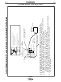
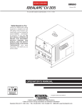
IDEALARC CV-400-I
June, 2002
For use with machine Code Numbers 10182, 10183,10084, 10085 & 10086
Safety Depends on You
Lincoln arc welding and cutting
equipment is designed and built
with safety in mind. However, your
overall safety can be increased by
proper installation ... and thoughtful operation on your part. DO
NOT INSTALL, OPERATE OR
REPAIR THIS EQUIPMENT
WITHOUT READING THIS
MANUAL AND THE SAFETY
PRECAUTIONS CONTAINED
THROUGHOUT. And, most
importantly, think before you act
and be careful.
CV-400-I
OPERATOR’S MANUAL
Copyright © 2002 Lincoln Global Inc.
• World's Leader in Welding and Cutting Products •
• Sales and Service through Subsidiaries and Distributors Worldwide •
Cleveland, Ohio 44117-1199 U.S.A. TEL: 216.481.8100 FAX: 216.486.1751 WEB SITE: www.lincolnelectric.com
i
i
SAFETY
WARNING
CALIFORNIA PROPOSITION 65 WARNINGS
Diesel engine exhaust and some of its constituents
are known to the State of California to cause cancer, birth defects, and other reproductive harm.
The Above For Diesel Engines
The engine exhaust from this product contains
chemicals known to the State of California to cause
cancer, birth defects, or other reproductive harm.
The Above For Gasoline Engines
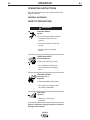
ARC WELDING CAN BE HAZARDOUS. PROTECT YOURSELF AND OTHERS FROM POSSIBLE SERIOUS INJURY OR DEATH.
KEEP CHILDREN AWAY. PACEMAKER WEARERS SHOULD CONSULT WITH THEIR DOCTOR BEFORE OPERATING.
Read and understand the following safety highlights. For additional safety information, it is strongly recommended that you
purchase a copy of “Safety in Welding & Cutting - ANSI Standard Z49.1” from the American Welding Society, P.O. Box
351040, Miami, Florida 33135 or CSA Standard W117.2-1974. A Free copy of “Arc Welding Safety” booklet E205 is available
from the Lincoln Electric Company, 22801 St. Clair Avenue, Cleveland, Ohio 44117-1199.
BE SURE THAT ALL INSTALLATION, OPERATION, MAINTENANCE AND REPAIR PROCEDURES ARE
PERFORMED ONLY BY QUALIFIED INDIVIDUALS.
FOR ENGINE
powered equipment.
1.h. To avoid scalding, do not remove the
radiator pressure cap when the engine is
hot.
1.a. Turn the engine off before troubleshooting and maintenance
work unless the maintenance work requires it to be running.
____________________________________________________
1.b.Operate engines in open, well-ventilated
areas or vent the engine exhaust fumes
outdoors.
____________________________________________________
1.c. Do not add the fuel near an open flame
welding arc or when the engine is running.
Stop the engine and allow it to cool before
refueling to prevent spilled fuel from vaporizing on contact with hot engine parts and
igniting. Do not spill fuel when filling tank. If
fuel is spilled, wipe it up and do not start
engine until fumes have been eliminated.
____________________________________________________
1.d. Keep all equipment safety guards, covers and devices in
position and in good repair.Keep hands, hair, clothing and
tools away from V-belts, gears, fans and all other moving
parts when starting, operating or repairing equipment.
____________________________________________________
1.e. In some cases it may be necessary to remove safety
guards to perform required maintenance. Remove
guards only when necessary and replace them when the
maintenance requiring their removal is complete.
Always use the greatest care when working near moving
parts.
___________________________________________________
1.f. Do not put your hands near the engine fan.
Do not attempt to override the governor or
idler by pushing on the throttle control rods
while the engine is running.
ELECTRIC AND
MAGNETIC FIELDS
may be dangerous
2.a. Electric current flowing through any conductor causes
localized Electric and Magnetic Fields (EMF). Welding
current creates EMF fields around welding cables and
welding machines
2.b. EMF fields may interfere with some pacemakers, and
welders having a pacemaker should consult their physician
before welding.
2.c. Exposure to EMF fields in welding may have other health
effects which are now not known.
2.d. All welders should use the following procedures in order to
minimize exposure to EMF fields from the welding circuit:
2.d.1. Route the electrode and work cables together - Secure
them with tape when possible.
2.d.2. Never coil the electrode lead around your body.
2.d.3. Do not place your body between the electrode and
work cables. If the electrode cable is on your right
side, the work cable should also be on your right side.
2.d.4. Connect the work cable to the workpiece as close as
possible to the area being welded.
___________________________________________________
1.g. To prevent accidentally starting gasoline engines while
turning the engine or welding generator during maintenance
work, disconnect the spark plug wires, distributor cap or
magneto wire as appropriate.
2.d.5. Do not work next to welding power source.
Mar ‘95
ii
ii
SAFETY
ELECTRIC SHOCK can
kill.
3.a. The electrode and work (or ground) circuits
are electrically “hot” when the welder is on.
Do not touch these “hot” parts with your bare
skin or wet clothing. Wear dry, hole-free
gloves to insulate hands.
3.b. Insulate yourself from work and ground using dry insulation.
Make certain the insulation is large enough to cover your full
area of physical contact with work and ground.
In addition to the normal safety precautions, if welding
must be performed under electrically hazardous
conditions (in damp locations or while wearing wet
clothing; on metal structures such as floors, gratings or
scaffolds; when in cramped positions such as sitting,
kneeling or lying, if there is a high risk of unavoidable or
accidental contact with the workpiece or ground) use
the following equipment:
• Semiautomatic DC Constant Voltage (Wire) Welder.
• DC Manual (Stick) Welder.
• AC Welder with Reduced Voltage Control.
3.c. In semiautomatic or automatic wire welding, the electrode,
electrode reel, welding head, nozzle or semiautomatic
welding gun are also electrically “hot”.
3.d. Always be sure the work cable makes a good electrical
connection with the metal being welded. The connection
should be as close as possible to the area being welded.
3.e. Ground the work or metal to be welded to a good electrical
(earth) ground.
3.f. Maintain the electrode holder, work clamp, welding cable and
welding machine in good, safe operating condition. Replace
damaged insulation.
3.g. Never dip the electrode in water for cooling.
3.h. Never simultaneously touch electrically “hot” parts of
electrode holders connected to two welders because voltage
between the two can be the total of the open circuit voltage
of both welders.
3.i. When working above floor level, use a safety belt to protect
yourself from a fall should you get a shock.
3.j. Also see Items 6.c. and 8.
ARC RAYS can burn.
4.a. Use a shield with the proper filter and cover
plates to protect your eyes from sparks and
the rays of the arc when welding or observing
open arc welding. Headshield and filter lens
should conform to ANSI Z87. I standards.
4.b. Use suitable clothing made from durable flame-resistant
material to protect your skin and that of your helpers from
the arc rays.
4.c. Protect other nearby personnel with suitable, non-flammable
screening and/or warn them not to watch the arc nor expose
themselves to the arc rays or to hot spatter or metal.
FUMES AND GASES
can be dangerous.
5.a. Welding may produce fumes and gases
hazardous to health. Avoid breathing these
fumes and gases.When welding, keep
your head out of the fume. Use enough
ventilation and/or exhaust at the arc to keep
fumes and gases away from the breathing zone. When
welding with electrodes which require special
ventilation such as stainless or hard facing (see
instructions on container or MSDS) or on lead or
cadmium plated steel and other metals or coatings
which produce highly toxic fumes, keep exposure as
low as possible and below Threshold Limit Values (TLV)
using local exhaust or mechanical ventilation. In
confined spaces or in some circumstances, outdoors, a
respirator may be required. Additional precautions are
also required when welding on galvanized steel.
5.b. Do not weld in locations near chlorinated hydrocarbon vapors
coming from degreasing, cleaning or spraying operations.
The heat and rays of the arc can react with solvent vapors to
form phosgene, a highly toxic gas, and other irritating
products.
5.c. Shielding gases used for arc welding can displace air and
cause injury or death. Always use enough ventilation,
especially in confined areas, to insure breathing air is safe.
5.d. Read and understand the manufacturer’s instructions for this
equipment and the consumables to be used, including the
material safety data sheet (MSDS) and follow your
employer’s safety practices. MSDS forms are available from
your welding distributor or from the manufacturer.
5.e. Also see item 1.b.
Mar ‘95
iii
iii
SAFETY
WELDING SPARKS can
cause fire or explosion.
6.a. Remove fire hazards from the welding area.
If this is not possible, cover them to prevent
the welding sparks from starting a fire.
Remember that welding sparks and hot
materials from welding can easily go through small cracks
and openings to adjacent areas. Avoid welding near
hydraulic lines. Have a fire extinguisher readily available.
6.b. Where compressed gases are to be used at the job site,
special precautions should be used to prevent hazardous
situations. Refer to “Safety in Welding and Cutting” (ANSI
Standard Z49.1) and the operating information for the
equipment being used.
6.c. When not welding, make certain no part of the electrode
circuit is touching the work or ground. Accidental contact
can cause overheating and create a fire hazard.
6.d. Do not heat, cut or weld tanks, drums or containers until the
proper steps have been taken to insure that such procedures
will not cause flammable or toxic vapors from substances
inside. They can cause an explosion even though they have
been “cleaned”. For information, purchase “Recommended
Safe Practices for the Preparation for Welding and Cutting of
Containers and Piping That Have Held Hazardous
Substances”, AWS F4.1 from the American Welding Society
(see address above).
6.e. Vent hollow castings or containers before heating, cutting or
welding. They may explode.
6.f. Sparks and spatter are thrown from the welding arc. Wear oil
free protective garments such as leather gloves, heavy shirt,
cuffless trousers, high shoes and a cap over your hair. Wear
ear plugs when welding out of position or in confined places.
Always wear safety glasses with side shields when in a
welding area.
6.g. Connect the work cable to the work as close to the welding
area as practical. Work cables connected to the building
framework or other locations away from the welding area
increase the possibility of the welding current passing
through lifting chains, crane cables or other alternate circuits. This can create fire hazards or overheat lifting chains
or cables until they fail.
6.h. Also see item 1.c.
CYLINDER may explode
if damaged.
7.a. Use only compressed gas cylinders
containing the correct shielding gas for the
process used and properly operating
regulators designed for the gas and
pressure used. All hoses, fittings, etc. should be suitable for
the application and maintained in good condition.
7.b. Always keep cylinders in an upright position securely
chained to an undercarriage or fixed support.
7.c. Cylinders should be located:
• Away from areas where they may be struck or subjected to
physical damage.
• A safe distance from arc welding or cutting operations and
any other source of heat, sparks, or flame.
7.d. Never allow the electrode, electrode holder or any other
electrically “hot” parts to touch a cylinder.
7.e. Keep your head and face away from the cylinder valve outlet
when opening the cylinder valve.
7.f. Valve protection caps should always be in place and hand
tight except when the cylinder is in use or connected for
use.
7.g. Read and follow the instructions on compressed gas
cylinders, associated equipment, and CGA publication P-l,
“Precautions for Safe Handling of Compressed Gases in
Cylinders,” available from the Compressed Gas Association
1235 Jefferson Davis Highway, Arlington, VA 22202.
FOR ELECTRICALLY
powered equipment.
8.a. Turn off input power using the disconnect
switch at the fuse box before working on
the equipment.
8.b. Install equipment in accordance with the U.S. National
Electrical Code, all local codes and the manufacturer’s
recommendations.
8.c. Ground the equipment in accordance with the U.S. National
Electrical Code and the manufacturer’s recommendations.
Mar ‘95
iv
iv
SAFETY
PRÉCAUTIONS DE SÛRETÉ
Pour votre propre protection lire et observer toutes les instructions et les précautions de sûreté specifiques qui parraissent
dans ce manuel aussi bien que les précautions de sûreté
générales suivantes:
Sûreté Pour Soudage A L’Arc
1. Protegez-vous contre la secousse électrique:
a. Les circuits à l’électrode et à la piéce sont sous tension
quand la machine à souder est en marche. Eviter toujours
tout contact entre les parties sous tension et la peau nue
ou les vétements mouillés. Porter des gants secs et sans
trous pour isoler les mains.
b. Faire trés attention de bien s’isoler de la masse quand on
soude dans des endroits humides, ou sur un plancher
metallique ou des grilles metalliques, principalement dans
les positions assis ou couché pour lesquelles une
grande partie du corps peut être en contact avec la
masse.
c. Maintenir le porte-électrode, la pince de masse, le câble
de soudage et la machine à souder en bon et sûr état
defonctionnement.
d.Ne jamais plonger le porte-électrode dans l’eau pour le
refroidir.
e. Ne jamais toucher simultanément les parties sous tension
des porte-électrodes connectés à deux machines à souder parce que la tension entre les deux pinces peut être le
total de la tension à vide des deux machines.
f. Si on utilise la machine à souder comme une source de
courant pour soudage semi-automatique, ces precautions
pour le porte-électrode s’applicuent aussi au pistolet de
soudage.
2. Dans le cas de travail au dessus du niveau du sol, se protéger contre les chutes dans le cas ou on recoit un choc. Ne
jamais enrouler le câble-électrode autour de n’importe quelle
partie du corps.
3. Un coup d’arc peut être plus sévère qu’un coup de soliel,
donc:
a. Utiliser un bon masque avec un verre filtrant approprié
ainsi qu’un verre blanc afin de se protéger les yeux du
rayonnement de l’arc et des projections quand on soude
ou quand on regarde l’arc.
b. Porter des vêtements convenables afin de protéger la
peau de soudeur et des aides contre le rayonnement de
l‘arc.
c. Protéger l’autre personnel travaillant à proximité au
soudage à l’aide d’écrans appropriés et non-inflammables.
4. Des gouttes de laitier en fusion sont émises de l’arc de
soudage. Se protéger avec des vêtements de protection
libres de l’huile, tels que les gants en cuir, chemise épaisse,
pantalons sans revers, et chaussures montantes.
5. Toujours porter des lunettes de sécurité dans la zone de
soudage. Utiliser des lunettes avec écrans lateraux dans les
zones où l’on pique le laitier.
6. Eloigner les matériaux inflammables ou les recouvrir afin de
prévenir tout risque d’incendie dû aux étincelles.
7. Quand on ne soude pas, poser la pince à une endroit isolé de
la masse. Un court-circuit accidental peut provoquer un
échauffement et un risque d’incendie.
8. S’assurer que la masse est connectée le plus prés possible
de la zone de travail qu’il est pratique de le faire. Si on place
la masse sur la charpente de la construction ou d’autres
endroits éloignés de la zone de travail, on augmente le risque
de voir passer le courant de soudage par les chaines de levage, câbles de grue, ou autres circuits. Cela peut provoquer
des risques d’incendie ou d’echauffement des chaines et des
câbles jusqu’à ce qu’ils se rompent.
9. Assurer une ventilation suffisante dans la zone de soudage.
Ceci est particuliérement important pour le soudage de tôles
galvanisées plombées, ou cadmiées ou tout autre métal qui
produit des fumeés toxiques.
10. Ne pas souder en présence de vapeurs de chlore provenant
d’opérations de dégraissage, nettoyage ou pistolage. La
chaleur ou les rayons de l’arc peuvent réagir avec les
vapeurs du solvant pour produire du phosgéne (gas fortement toxique) ou autres produits irritants.
11. Pour obtenir de plus amples renseignements sur la sûreté,
voir le code “Code for safety in welding and cutting” CSA
Standard W 117.2-1974.
PRÉCAUTIONS DE SÛRETÉ POUR
LES MACHINES À SOUDER À
TRANSFORMATEUR ET À
REDRESSEUR
1. Relier à la terre le chassis du poste conformement au code
de l’électricité et aux recommendations du fabricant. Le dispositif de montage ou la piece à souder doit être branché à
une bonne mise à la terre.
2. Autant que possible, I’installation et l’entretien du poste
seront effectués par un électricien qualifié.
3. Avant de faires des travaux à l’interieur de poste, la
debrancher à l’interrupteur à la boite de fusibles.
4. Garder tous les couvercles et dispositifs de sûreté à leur
place.
Mar. ‘93
v
v
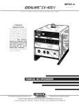
Thank You
for selecting a QUALITY product by Lincoln Electric. We want you
to take pride in operating this Lincoln Electric Company product
••• as much pride as we have in bringing this product to you!
Please Examine Carton and Equipment For Damage Immediately
When this equipment is shipped, title passes to the purchaser upon receipt by the carrier. Consequently, Claims
for material damaged in shipment must be made by the purchaser against the transportation company at the
time the shipment is received.
Please record your equipment identification information below for future reference. This information can be
found on your machine nameplate.
Model Name & Number _____________________________________
Code & Serial Number _____________________________________
Date of Purchase
_____________________________________
Whenever you request replacement parts for or information on this equipment always supply the information
you have recorded above.
Read this Operators Manual completely before attempting to use this equipment. Save this manual and keep it
handy for quick reference. Pay particular attention to the safety instructions we have provided for your protection.
The level of seriousness to be applied to each is explained below:
WARNING
This statement appears where the information must be followed exactly to avoid serious personal injury or
loss of life.
CAUTION
This statement appears where the information must be followed to avoid minor personal injury or damage to
this equipment.
TABLE OF CONTENTS
Page
Installation .......................................................................................................Section A
Technical Specifications ........................................................................................A-1
Select Suitable Location ........................................................................................A-2
Input Connections..................................................................................................A-2
Field Installed Options ...........................................................................................A-3
Required Equipment - Control Cable Connections................................................A-3
Output Connections. ..............................................................................................A-3
Paralleling .............................................................................................................A-4
Connection of Auxiliary Equipment to Wire Feeder Receptacle ............................A-4
Operation .........................................................................................................Section B
Safety Precautions ................................................................................................B-1
General Description ...............................................................................................B-2
Recommended Processes and Equipment ...........................................................B-2
Operational Features and Controls........................................................................B-2
Design Features ....................................................................................................B-2
Limitations..............................................................................................................B-2
Power Source Operation .......................................................................................B-2
Duty Cycle .............................................................................................................B-2
Controls and Settings ............................................................................................B-3
Graphic Symbols ...................................................................................................B-4
Output Panel Connections.....................................................................................B-5
Case Back Connections ........................................................................................B-6
Starting the Machine..............................................................................................B-7
Adjusting the Output Voltage using the Digital Meter ............................................B-7
Local/Remote Switch Operation ............................................................................B-7
Auxiliary Power ......................................................................................................B-7
Overload Protection ...............................................................................................B-7
Accessories .....................................................................................................Section C
Factory/Field Installed Options ..............................................................................C-1
Compatible Lincoln Equipment..............................................................................C-1
Maintenance ....................................................................................................Section D
Safety Precautions ................................................................................................D-1
General Maintenance ............................................................................................D-1
Machine and Circuit Protection..............................................................................D-1
Troubleshooting ..............................................................................................Section E
Safety Precautions.................................................................................................E-1
How to Use Troubleshooting Guide.......................................................................E-1
Built-in Diagnostic Routines and Error Codes -Troubleshooting Guide.................E-2
Machine -Troubleshooting Guide...........................................................................E-3
Options -Troubleshooting Guide............................................................................E-6
Procedure for Replacing PC Boards......................................................................E-7
Control and Meter PC Board Troubleshooting Procedures ...................................E-7
Output Voltage, Fault Protection, Snubber Circuit and K857 Remote Control Checks....................E-8
Diagrams ..........................................................................................................Section F
Parts Manual ....................................................................................................Appendix
vi
INSTALLATION
A-1
A-1
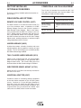
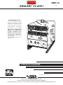
TECHNICAL SPECIFICATIONS – IDEALARC CV-400-I
INPUT - THREE PHASE ONLY
Standard
Voltage
220/380/440/3/50/60
Input Current at
Rated Output
100% Duty Cycle 60/35/30
60% Duty Cycle 62/36/31
Code
Number
10183 (Export, NEMA Rated)
230/400/3/50/60
100% Duty Cycle 58/34
60% Duty Cycle 60/33
10182 (European, IEC Rated)
380/500/3/50/60
100% Duty Cycle 35/26
60% Duty Cycle 36/27
10184 (Export, NEMA Rated)
415/3/50/60
100% Duty Cycle 32
60% Duty Cycle 33
10185 (Export, NEMA Rated)
200/400/3/50/60
100% Duty Cycle 66/33
60% Duty Cycle 68/34
10186 (Export, NEMA Rated)
RATED OUTPUT
Duty Cycle
NEMA Class II (60)
100% Duty Cycle
Amps
400
300
Volts at Rated Amperes
36
32
IEC 974-1 60%
100% Duty Cycle
400
300
34
29
OUTPUT
Welding Current/Voltage Range
(Continuous)
50A/7V - 400A/37V
DC
Efficiency at 100% Load
NEMA Rated 78%, IEC Rated 68%
Normal Open Circuit Voltage
10-43
MAX OCV: 50
Auxiliary Power
42 Volts AC, 10 Amps
115 Volts AC, 5 Amps (Except Code 10182)
220 Volts AC, 2 Amps
Input kVA
NEMA 60% Load - 23.6, IEC 60% Load - 23.2
NEMA 100% Load - 22.9, IEC 100% Load - 23.2
( All Circuit Breaker Protected)
MISC. INFORMATION
Idle Power
825W
Power Factor at Rated Load
.80
Idle Current - Amps
16/9/8
Power Factor at 100% Load
.55
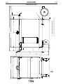
PHYSICAL DIMENSIONS
Height
21.5 in.
546 mm
Width
19.5 in.
(Lift bail, add 3.12 in)
Depth
27.0 in.
495 mm
(Lift bail, add 80 mm)
686 mm
CV-400-I
Weight
300 lbs
(137 kg)
A-2
A-2
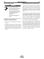
INSTALLATION
Read entire installation section before starting
installation.
INPUT CONNECTIONS
SAFETY PRECAUTIONS
Be sure the voltage, phase, and frequency of the input
power is as specified on the welder nameplate.
WARNING
ELECTRIC SHOCK can kill.
• Only qualified personnel should
perform this installation.
• Turn the input power OFF at the disconnect switch or fuse box before working on
this equipment.
• Turn the Power switch on the CV-400-I
“OFF” before connecting or disconnecting output cables, wire feeder or remote
connections, or other equipment.
• Do not touch electrically hot parts.
• Always connect the Idealarc CV-400-I
grounding terminal (located on the welder
base near the reconnect panel) to a good
electrical earth ground.
SELECT SUITABLE LOCATION
Place the welder where clean cooling air can freely
circulate in through the side louvers and out through
the rear louvers. Dirt, dust or any foreign material that
can be drawn into the welder should be kept at a
minimum. Failure to observe these precautions can
result in excessive operating temperatures and
nuisance shut-downs. Idealarc CV-400-I power
sources carry an IP23 enclosure rating. They are
rated for use in damp, dirty environments subject to
occasional falling water such as rain.
STACKING
The CV-400-I may be stacked three-high provided the
bottom machine is on a stable, hard, level surface. Be
sure that the two pins in the roof fit into the slots in the
base of the CV-400-I above it.
TILTING
Do not place the machine on a surface that is inclined
enough to create a risk of the machine falling over.
Gain access to the input reconnect panel by removing
the right case side of the CV-400-I (side nearest to the
Power switch.)
Have a qualified electrician connect the input leads to
L1, L2, and L3 of the input reconnect panel in accordance with the National Electrical Code, all local
codes, and the connection diagram located on the
inside of the right case side. Use a three phase line.
The frame of the welder must be grounded. A ground
terminal marked with the symbol
located on the
base of the machine is provided for this purpose. See
the National Electrical Code for details on proper
grounding methods.
Fuse the input circuit with the recommended super lag
fuses. Choose an input and grounding wire size
according to local codes or use the following table.
"Delay type"1 circuit breakers may be used in place of
fuses. Using fuses or circuit breakers smaller than
recommended may result in "nuisance" tripping from
welder inrush currents even if not welding at high currents.
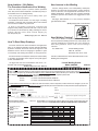
RECOMMENDED INPUT WIRE AND FUSE SIZES
Type 75°C
Fuse
Input
Type 75°C
Copper
(Super Lag) Ampere Copper Wire in Ground Wire in
Input
Voltage / or Breaker Rating on Conduit AWG Conduit AWG
Size
Nameplate (IEC) Sizes
(IEC) Sizes
Frequency
208/60
100
66
4 (25 mm2)
8 (10mm2)
230/60
90
60
4 (25 mm2)
8 (10mm2)
30
10 (6mm2)
10 (6mm2)
10 (6mm2)
460/60
50
575/60
40
24
10 (6mm2)
200/50/60
100
66
4 (25 mm2)
8 (10mm2)
220/50/60
90
61
4 (25 mm2)
8 (10mm2)
58
4 (25 mm2)
8 (10mm2)
10 (6mm2)
230/50/60
90
380/50/60
60
35
8 (10mm2)
400/50/60
50
33
8 (10mm2)
10 (6mm2)
415/50/60
50
32
8 (10mm2)
10 (6mm2)
31
10 (6mm2)
10 (6mm2)
26
10 (6mm2)
10 (6mm2)
440/50/60
500/50/60
50
40
1Also called “inverse time” or “thermal/magnetic” circuit breakers; circuit
breakers which have a delay in tripping action that decreases as the magnitude of the current increases.
CV-400-I
A-3
A-3
INSTALLATION
FIELD INSTALLED OPTIONS
Connection of Remote Control (K857)
For installation of compatible field installed options
(see the ACCESSORIES section of this manual and
refer to the instructions included with those options.
NOTE: The K864 Remote Control Adapter is required
to install the K857.
REQUIRED EQUIPMENT-CONTROL
CABLE CONNECTIONS
Follow the instructions below which are appropriate
for the wire feeder that will be used.
LN-7 to CV-400-I
Plug the K864 Remote Control Adapter into the power
source's 14-pin receptacle. Plug the K857 Remote
Control into the 6-pin receptacle of the K864 adapter.
If possible, tape the Remote cable to the heavy output
leads, so they can protect the smaller Remote cable
from damage and abuse.
OUTPUT CONNECTIONS
a) Turn the CV-400-I Power switch to the "OFF"
position.
Output cables must have Magnum Twist-Mate™ plugs
for connection to the CV-400-I. Order K852-95 for
connecting 2/0-3/0 (70-95 mm2) cables. Refer to
S18737 for instructions on installing these plugs.
b) Connect the LN-7 control cable to the wire feeder
receptacle on the CV-400-I.
Use the shortest possible cable lengths. See Table
A.1 for recommended cable sizes based on length.
c) See OUTPUT CONNECTIONS for connection of
work and electrode cables.
Connect the positive output lead to the terminal
marked "+". The negative output lead can be hooked
to either the low inductance terminal (marked "
") or the high inductance terminal (marked
"
").
LN-25 to CV-400-I
a) Turn the CV-400-I Power switch to the "OFF"
position.
b) Plug a K484 jumper plug into the CV-400-I wire
feeder receptacle.
c) See OUTPUT CONNECTIONS for connection of
work and electrode cables.
WARNING
The output terminals are energized at all times when
the K484 is plugged in.
------------------------------------------------------------------------
LN-742 to CV-400-I
a) Turn the CV-400-I Power switch to the "OFF"
position.
b) Connect the LN-742 control cable to the wire
feeder receptacle on the CV-400-I.
c) See OUTPUT CONNECTIONS for connection of
work and electrode cables.
CV-400-I
TABLE A.1
Cable Sizes for Combined Lengths of Copper
Electrode and Work Cable
Machine Size
Lengths up to
150 ft
150 to 200 ft
300 A 100%
(400 A 60%)
2/0 (70mm2)
3/0 (95mm2)
A-4
INSTALLATION
PARALLELING
The CV-400-I is not designed to be paralleled with any
other power source.
CONNECTION OF AUXILIARY EQUIPMENT
TO THE WIRE FEEDER RECEPTACLE
Occasionally, it may be necessary to make connection
to the circuits present in the 14-pin wire feeder receptacle. These circuits, such as the auxiliary voltage,
contactor, and remote control circuits, may be
accessed with a K867 Universal Adapter. This
adapter plugs into the receptacle and provides the
user with short wire leads for connections. Refer to
the instructions provided with the K867, as well as the
wiring diagram for the CV-400-I power source, for
details on making those connections. For your convenience, wire feeder connection details are shown in
the DIAGRAM section.
NOTE: If you intend to use a standard Lincoln wire
feeder, order the appropriate input cable for
the specific feeder. It will make all of the control and power connections between the CV400-I and the wire feeder WITHOUT the
need for a K867 Universal Adapter.
CV-400-I
A-4
B-1
OPERATION
OPERATING INSTRUCTIONS
Read and understand this entire section before operating the machine.
GENERAL WARNINGS
SAFETY PRECAUTIONS
WARNING
ELECTRIC SHOCK
can kill.
• Do not touch electrically live parts
or electrode with skin or wet
clothing.
• Insulate yourself from work and
ground.
• Always wear dry insulating
gloves.
FUMES AND GASES
can be dangerous.
• Keep your head out of fumes.
• Use ventilation or exhaust to
remove fumes from breathing
zone.
WELDING SPARKS
can cause fire or
explosion
• Keep flammable material away.
• Do not weld on containers that
have held combustibles.
ARC RAYS
can burn.
• Wear eye, ear and body
protection.
Observe additional Safety Guidelines detailed
throughout this manual.
CV-400-I
B-1
B-2
OPERATION
B-2
• Circuit breaker protected.
CAUTION
When using a CV-400-I power source with wire feeders,
there will be a small spark if the electrode contacts the work
or ground within several seconds after releasing the trigger.
When used with some wire feeders with the electrical trigger
interlock in the ON position, the arc might restart if the electrode
touches the work or ground during these several seconds.
------------------------------------------------------------------------
GENERAL DESCRIPTION
• 115 VAC, 5 amp auxiliary power available for the wire
feeder; circuit breaker protected. (Except Code 10182).
• 220 VAC, 2 amp Auxiliary power available for water coolers, using standard Continental European receptacle.
• Magnum Twist-Mate™ output receptacles.
• Single MS-type (14-pin) connection for wire feeder.
• Solid state controls, with line voltage compensation.
The CV 400-I is a constant voltage DC power source
designed for the GMAW process with limited FCAW capability as well. It features an international rating of 400 amps,
36 volts, at 60% duty cycle. It also has the capacity to run
at 300 amps, 32 volts, 100% duty cycle.
The CV 400-I is available as a European model with 42 VAC
auxiliary power only, or as an export model with both 42 VAC
and 115 VAC auxiliary power. No options are available other
than input voltage.
The European model of the CV 400-I features an all graphic
nameplate and has an IEC 974-1 S Rating for use in environments with an increased hazard of electric shock.
RECOMMENDED PROCESSES AND
EQUIPMENT
The CV-400-I is capable of solid wire welding within
the rated output capacity of the machine. It is also
capable of welding with the following flux-cored wires:
NR-152, NR-211, NS-3M, NR-203 Ni 1%, and
Outershield® 70 and 71.
The CV-400-I (Export) is recommended for use with
the LN-7, LN-742 and LN-25 wire feeder models. The
CV-400-I (European) does not provide 115 VAC auxiliary power for the LN-7 models.
OPERATIONAL FEATURES AND
CONTROLS
• Optional remote control capability.
DESIGN FEATURES
• "Clean" appearance and simple controls -- easy to operate.
• Electronic and thermostatic protection from overloads.
• Submersion dipping of assembled transformer, choke, and
rectifier in special sealing/insulating material gives extra protection against moisture and corrosive atmospheres.
• Microprocessor based Control PC Board has built-in
diagnostic routines.
• Compact size, requires only 19" x 26" footprint.
• Modular construction for easy servicing.
• Recessed panels protect output studs and controls.
Large safety margins and protective circuits protect
rectifiers from transient voltages and high currents.
LIMITATIONS
The CV-400-I is intended only for use with the following FCAW electrodes: NR-152, NR-211, NR-203 Ni
1%, NS-3M, Outershield 70 and 71. The machine has
been designed primarily for the GMAW process.
POWER SOURCE OPERATION
• Two inductance positions: operator can choose the
optimum output characteristics.
• Solid State Output Contactor: no noise, no moving
parts to wear.
Be sure the CV-400-I is properly installed, and that all
accessories are properly hooked up before attempting
operation.
DUTY CYCLE
• Digital Voltmeter/Ammeter is standard.
300 Amps, 32 Volts at 100%
400 Amps, 36 Volts at 60%
• Power on/off switch.
Duty Cycle is based on operation for a 10 minute period.
• 42 VAC, 10 amp auxiliary power available for the wire feeder.
CV-400-I
B-3
B-3
OPERATION
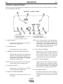
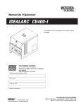
CONTROLS AND SETTINGS
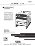
All operator controls and adjustments are located on the case front of the CV-400-I. Refer to Figures B.1, and B.2
and corresponding explanations.
FIGURE B.1 - CONTROL PANEL
D
E
F
A.
B.
C.
D.
E.
G
C
H
B
POWER SWITCH
VOLTAGE ADJUSTMENT
THERMAL PROTECTION INDICATION LIGHT
VOLTS / AMPS SWITCH
DIGITAL VOLTMETER / AMMETER
A. POWER SWITCH
- A two-position toggle switch.Controls the
input power to the CV-400-I.
B. VOLTAGE ADJUST
- Controls the CV-400-I output voltage.
F.
G.
H.
J.
J
A
42 VOLT CIRCUIT BREAKER
115 VOLT CIRCUIT BREAKER
LOCAL / REMOTE SWITCH
WIRE FEEDER VOLTMETER SWITCH
NOTE: Due to voltage drops in the welding cables
and at cable connection points, the actual arc
voltage may be lower than that displayed on
the voltmeter. Use welding cables of the
proper capacity and make sure all connections are tight to minimize this effect.
F. 42 VOLT CIRCUIT BREAKER
C. THERMAL PROTECTION INDICATION LIGHT
- Indicates that the protection thermostat has
activated. The digital meter will display "E10"
when this occurs. When the light turns off,
the machine will be capable of supplying
welding output power again.
-Protects the 42 volt 41-42 circuit in the wire
feeder receptacle from overloads and shorts.
If this circuit breaker opens, the CV-400-I will
work normally. However, any equipment
powered by the 42 volt circuit will not work.
G. 115 VOLT CIRCUIT BREAKER
NOTE: Leaving the power switch in the "ON" position will result in the most rapid cooling.
-Protects the 115 volt 31-32 circuit in the wire
feeder receptacle from overloads and shorts.
If this circuit breaker opens, the CV-400-I will
work normally. However, any equipment
powered by the 115 volt circuit will not work.
D. VOLTS/AMPS SWITCH
- Selects either output current or arc voltage
to be displayed on the digital meter.
H. LOCAL/REMOTE SWITCH
E. DIGITAL VOLTMETER/AMMETER
- Displays the CV-400-I output current, or the
arc voltage.
CV-400-I
-Determines whether the welding voltage is
controlled at the CV-400-I, or controlled
remotely by a remote output control (such as
a K857).
B-4
B-4
OPERATION
-When welding electrode negative (most
Innershield electrodes) set the switch to "-".
J. WIRE FEEDER VOLTMETER SWITCH
-This switch selects the polarity of the wire
feeder voltmeter, if so equipped. When welding electrode positive (MIG, Outershield and
some Innershield processes) set the switch
to "+".
-This switch has no effect on the welding
polarity. In fact, if the wire feeder being used
does not have a voltmeter, the setting of this
switch has no effect.
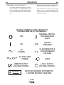
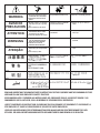
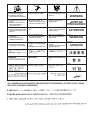
GRAPHIC SYMBOLS THAT APPEAR ON
THIS MACHINE OR IN THIS MANUAL
OFF
THERMAL PROTECTION INDICATOR
LIGHT
ON
CIRCUIT
BREAKER
AC
POWER
CLOCKWISE ROTATION INCREASES
VOLTAGE
AC AUXILIARY
POWER
REMOTE OUTPUT
VOLTAGE CONTROL
WARNING
INPUT
LOCAL OUTPUT
VOLTAGE CONTROL
INDICATES WARNING INFORMATION
LOCATED ON RIGHT CASE SIDE
CV-400-I
B-5
B-5
OPERATION
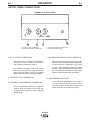
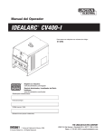
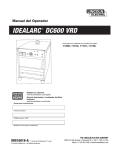
OUTPUT PANEL CONNECTIONS
FIGURE B.2 - OUTPUT PANEL
A
D
C
B
A. POSITIVE OUTPUT CONNECTION
B. LOW INDUCTANCE NEG. CONNECTION
C. HIGH INDUCTANCE NEG. CONNECTION
D. WIRE FEEDER RECEPTACLE
A., B., C. OUTPUT CONNECTORS
C. HIGH INDUCTANCE NEGATIVE OUTPUT CONNECTION.
-Each connector is a Magnum Twist-Mate™,
receptacle. Insert a mating Twist-Mate™
plug, and twist clockwise to secure.
-The high inductance connection is more suitable for short arc welding heavier weldments
or when using 75% Argon/25% CO2 shielding gas. This connection produces a softer
arc and a flatter bead with more wash-in than
the low inductance connection. A spray type
transfer is possible with either connection.
For GMAW processes, and most FCAW
processes, the positive output connection
goes to the wire feeder. One of the negative
output connections goes directly to the work.
A. POSITIVE OUTPUT CONNECTION.
D. WIRE FEEDER RECEPTACLE
B. LOW INDUCTANCE NEGATIVE CONNECTION.
-The low inductance connection is typically
used for short arc welding of mild steel, particularly on thin materials or when using CO2
shielding gas.
CV-400-I
-14-pin MS style receptacle for wire feeder.
Provides connections for auxiliary power,
contactor closure, remote output control, wire
feeder voltmeter sense lead, and ground.
B-6
B-6
OPERATION
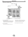
CASE BACK CONNECTIONS
FIGURE B.3 - BACK PANEL
B
A
C
A. 220 VAC RECEPTACLE
B. CIRCUIT BREAKER
C. CABLE CLAMP FOR INPUT CABLES
A. 220 VAC RECEPTACLE
Continental European type, nonpolarized, grounded receptacle (also known as a "Schuko" type) for
connection of water coolers or other equipment.
loads and shorts. If this breaker opens, the CV
400-I will work normally; however, equipment powered by the 220 volt receptacle will not work.
C. CABLE CLAMP FOR INPUT CABLES
B. CIRCUIT BREAKER
Protects the 220 volt auxiliary circuit from over-
CV-400-I
B-7
B-7
OPERATION
STARTING THE MACHINE
AUXILIARY POWER
The power switch at the extreme right side of the control panel energizes the CV-400-I.
42 volt AC auxiliary power, as required for some wire
feeders, is available through the wire feeder receptacle. A 10 amp circuit breaker protects the 42 volt circuit from overloads.
ADJUSTING THE OUTPUT VOLTAGE
USING THE DIGITAL METER
The digital meters in the CV-400-I incorporate a voltage preset function. This allows the operator to set the desired
welding voltage before striking an arc. The digital meters
can also display welding current.
To make use of the voltage preset function, the Volts/Amps
switch must be in the "Volts" position. Turn the Voltage
Adjust knob until the digital meter displays the desired welding voltage. (See below if an external power source remote
control is installed.)
When an arc is struck, the digital meter displays the actual
welding voltage, as measured at the CV-400-I output terminals.
NOTE: The arc voltage at the electrode may be as much as
two volts different from the CV-400-I output terminal
voltage. This is due to voltage drops present in the
welding cables, cable connections, and welding
gun. To minimize these drops, use cables of adequate capacity, and make sure all connections are
clean and tight. Because of these voltage drops,
you may have to preset the CV-400-I for a slightly
higher welding voltage than your procedure calls for.
To read welding current, set the Volts/Amps switch to the
"Amps" position. The welding current will be displayed
whenever an arc is struck.
LOCAL/REMOTE SWITCH OPERATION
If voltage control is desired at the CV-400-I, the
Local/Remote switch must be in the "Local" position. The
Voltage Adjust on the front panel can be used to adjust the
CV-400-I output. (The remote control, even if connected,
will have no effect if the switch is in the "Local" position).
To use a remote control, such as the K857 (see INSTALLATION section), place the Local/Remote switch (see Figure
B.1) in the "Remote" position. The remote control now controls the output voltage, in the manner described above.
This control may be adjusted while welding to change the
CV-400-I output.
CV-400-I Export machines only can also supply 115
volt AC auxiliary power through the wire feeder receptacle. A 5 amp circuit breaker protects the 115 volt
circuit from overloads.
The CV-400-I can supply 220 volt AC power at 2
amps for powering water coolers or other equipment.
This auxiliary power is available from the Continental
European type receptacle mounted on the case back.
A 2 amp circuit breaker, located next to the receptacle, protects this auxiliary from overloads.
NOTE: Do not use circuits 2 or 4 for control of auxiliary loads. (The 2-4 circuit is isolated from the
31-32 and 41-42 circuits.)
CAUTION
Note that some types of equipment, especially pumps
and large motors, have starting currents which are
significantly higher than their running current. These
higher starting currents may cause the circuit breaker
to open. If this situation occurs, the user should refrain
from using the CV-400-I auxiliary power for that equipment.
___________________________________________
OVERLOAD PROTECTION
This welder has thermostatic protection from excessive duty cycles, overloads, loss of cooling, and high
ambient temperatures. When the welder is subjected
to an overload or loss of cooling, a thermostat will
open. This condition will be indicated by the illumination of the yellow Thermostatic Protection Light on the
case front (see Figure B.1).The fan will continue to run
to cool the power source. No welding is possible until
the machine is allowed to cool and the Thermostatic
Protection Light goes out.
CV-400-I
C-1
ACCESSORIES
FACTORY INSTALLED
OPTIONS/ACCESSORIES
C-1
COMPATIBLE LINCOLN EQUIPMENT
There are no factory installed options/accessories on
the CV-400-I.
FIELD INSTALLED OPTIONS
The CV-400-I is intended for use with the LN-7, LN742, and LN-25 wire feed units. Use the Cables / Kits
listed below to make connection easily:
LN-7 / LN-7GMA*
Requires K480 Input Cable
LN-25
Requires K484 Jumper Plug Kit
LN-25 w/K444-1
Remote Voltage
Control Kit
Requires K864 Remote Control
Adapter and K484 Jumper Plug
Kit
LN-742 / LN-742H
Requires K591 Input Cable
REMOTE VOLTAGE CONTROL (K857)
The K857 consists of a control box with 25 feet (7.6
m) of four conductor cable. Installation of a K857
Remote Voltage Control in the CV-400-I requires a
K864 Remote Control Adapter. Refer to the instructions provided with the K857 for hookup to the CV400-I. When properly connected, and with the CV400-I Local-Remote Switch in the "Remote" position,
the K857 functions the same as the CV-400-I Voltage
Adjust control, enabling minimum to maximum output
voltage adjustment of the CV-400-I.
* European model CV-400-I does not provide 115 VAC auxiliary power for LN-7
models.
UNDERCARRIAGE (K835)
Includes front casters, a handle, a bracket, and a rear
wheeled platform that is capable of carrying one gas
cylinder. The CV-400-I lifting eye is not functional with
the K835 undercarriage installed.
TWO-CYLINDER UNDERCARRIAGE (K874)
Platform type undercarriage that can accommodate
either one or two gas bottles, or one gas bottle and a
Magnum water cooler. The CV-400-I lifting eye is not
functional when the K874 undercarriage is installed.
WIRE FEEDER SWIVEL MOUNT (K178-1)
Allows an LN-7 or LN-742 to be securely mounted on
the roof of a CV-400-I.
UNIVERSAL ADAPTER (K867)
Provides a means of connecting auxiliary equipment
to the wire feeder receptacle on the CV-400-I power
source. Consists of a 14-pin MS-type (Amphenol)
plug with 8 inch (0.2 meter) long flex leads, one for
each circuit present in the wire feeder receptacle. Not
required when using a standard wire feeder input
cable, such as a K480, with a Lincoln wire feeder.
CV-400-I
D-1
MAINTENANCE
SAFETY PRECAUTIONS
D-1
MACHINE AND CIRCUIT PROTECTION
WARNING
The CV-400-I Control PC Board has built-in diagnostic
routines to alert the operator when trouble exists.
When a trouble condition occurs, the CV-400-I meter
will display an error code, in the form "EXX", where
"XX" refers to a specific error. See TROUBLESHOOTING section for an explanation of the error
codes.
ELECTRIC SHOCK can kill.
• Only qualified personnel should
perform this maintenance.
• Turn the input power OFF at the
disconnect switch or fuse box
before working on this
equipment.
The power source is thermostatically protected
against overload or insufficient cooling. If the machine
is overloaded, the thermostat will open, thermal protection indicator light will turn on, and the output will
be zero. The fan will continue to run and auxiliary
power will still be available. The thermostat will
remain open until the machine cools, at which time it
will close and the output will again be available.
• Do not touch electrically hot
parts.
GENERAL MAINTENANCE
1. The fan motor has sealed bearings which require
no service.
2. In extremely dusty locations, dirt may clog the air
channels causing the welder to run hot with premature tripping of thermal protection. Blow out the
welder with low pressure air at regular intervals to
eliminate excessive dirt and dust build-up on internal parts.
The CV-400-I is electronically protected against overloads and accidental short circuits. The overload protection circuit automatically reduces the output current
to a safe value when an overload is detected. If the
circuitry senses a short circuit, it will shut off the CV400-I output. The short circuit protection circuit can
be reset by turning the CV-400-I Power switch OFF
for at least 10 seconds. Remove the short before
turning the Power switch ON again.
CV-400-I
E-1
TROUBLESHOOTING
E-1
HOW TO USE TROUBLESHOOTING GUIDE
WARNING
Service and Repair should only be performed by Lincoln Electric Factory Trained Personnel.
Unauthorized repairs performed on this equipment may result in danger to the technician and
machine operator and will invalidate your factory warranty. For your safety and to avoid
Electrical Shock, please observe all safety notes and precautions detailed throughout this
manual.
__________________________________________________________________________
This Troubleshooting Guide is provided to
help you locate and remedy possible problems with machine setup or operation.
Simply follow the three-step procedure
listed below.
Step 1. LOCATE PROBLEM (SYMPTOM).
Look under the column labeled “PROBLEM
(SYMPTOMS)”. This column describes possible symptoms that the machine may
exhibit. Find the listing that best describes
the symptom that the machine is exhibiting.
Symptoms are grouped into three main categories: output problems, function problems, welding problems.
Step 2. PERFORM EXTERNAL TESTS.
The second column labeled “POSSIBLE
AREAS OF MISADJUSTMENT(S)” lists the
obvious external possibilities that may contribute to the machine symptom. Perform
these tests/checks in the order listed. In
general, these tests can be conducted without removing the case wrap-around cover.
Step 3. PERFORM COMPONENT TESTS.
If you have exhausted all of the recommended tests in Step 2, Consult your Local
Authorized Field Service Facility.
CAUTION
If for any reason you do not understand the test procedures or are unable to perform
the tests/repairs safely, contact your LOCAL AUTHORIZED LINCOLN ELECTRIC
FIELD SERVICE FACILITY for assistance before you proceed.
_____________________________________________________________________
CV-400-I
E-2
E-2
TROUBLESHOOTING
Observe all Safety Guidelines detailed throughout this manual
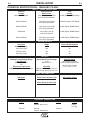
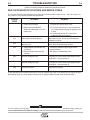
BUILT-IN DIAGNOSTIC ROUTINES AND ERROR CODES
The CV-400-I Meter PC Board displays error codes when certain trouble conditions exist. The error codes, trouble conditions, and possible remedies are listed below.
ERROR
CODE
E00
TROUBLE
REMEDY
1. Output short circuited.
1. Turn power off. Remove short circuit.
2. May be encountered while
starting or welding with 1/16" aluminum wire.
2. a) Turn power off to clear error. Use recommended
wfs, voltage settings and angle of approach of wire
to work.
b) If problem still persists, call Local Lincoln
Authorized Field Service Facility.
E10
Thermostat circuit has opened.
Allow machine to cool. Be sure to provide adequate
ventilation for machine.
E20
Memory error.
See PC Board Troubleshooting Procedure.
E30
1. Voltage Adjust potentiometer not
connected.
2. Remote Control not functioning
correctly.
1. Check wiring between Voltage Adjust and the
Control PC Board.
2. See Options Troubleshooting Guide.
E40
Input line voltage too low.
Turn power off. Insure machine input voltage is within
specifications. Turn power back on.
E50
Input line voltage too high.
Turn power off. Insure machine input voltage is within
specifications. Turn power back on.
E60
Overload condition.
Reduce load on machine.
If, after attempting the remedies listed above, the error condition still exists, the problem may be with the wiring in
the following areas: the shunt (leads 218 and 219), or voltage feedback (leads 213B, 214B and 224B).
CAUTION
If for any reason you do not understand the test procedures or are unable to perform the tests/repairs safely, contact your
Local Lincoln Authorized Field Service Facility for technical troubleshooting assistance before you proceed.
CV-400-I
E-3
E-3
TROUBLESHOOTING
Observe all Safety Guidelines detailed throughout this manual
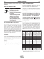
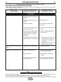
MACHINE TROUBLESHOOTING GUIDE
Not all trouble conditions can be recognized by the PC board, and displayed as error codes. The following guide
covers most other trouble conditions.
PROBLEMS
(SYMPTOMS)
POSSIBLE AREAS OF
MISADJUSTMENTS(S)
RECOMMENDED
COURSE OF ACTION
PROBLEMS
Machine has no output.
1. Secondary contactor circuit (2
1. Check 2 and 4 circuit wiring.
and 4 wire feeder receptacle) not
working.
2. Electrode or work lead loose or
broken.
2. Repair connection.
3. Defective PC Board.
3. See PC Board Troubleshooting
Procedure.
4. Protective circuits operating due
to output short circuit.
4. Turn power off. Remove output short
circuit.
5. If using an LN-25, K484 jumper
plug kit not making connection
between 2 & 4 in wire feeder
receptacle.
5. Check for continuity between pins C
& D in the K484.
6. If welding with 1/16" aluminum
6. a) Turn power off to clear error. Use
wire and machine is flashing E00.
recommended wfs, voltage settings and angle of approach of
wire to work.
b) If problem still persists, call Local Lincoln
Authorized Field Service Facility.
Machine has minimum output and no 1. Voltage Control misconnected.
control.
1. Voltage Control wiring.
Machine has low output and no con- 1. Open in feedback circuitry.
trol.
1. Check wiring and control and PC
board wiring harness plugs.
2. Faulty PC Board.
2. See PC Board Troubleshooting
Procedure.
3. Voltage Adjust potentiometer
circuit open (lead 75).
3. Check and replace potentiometer if
faulty. Check wiring of lead #75.
CAUTION
If for any reason you do not understand the test procedures or are unable to perform the tests/repairs safely, contact your
Local Lincoln Authorized Field Service Facility for technical troubleshooting assistance before you proceed.
CV-400-I
E-4
E-4
TROUBLESHOOTING
Observe all Safety Guidelines detailed throughout this manual
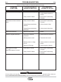
PROBLEMS
(SYMPTOMS)
POSSIBLE AREAS OF
MISADJUSTMENTS(S)
RECOMMENDED
COURSE OF ACTION
PROBLEMS
Thermal Protection Indicator light is
on.
1. Thermostat circuit has opened.
1. Allow machine to cool. Be sure to
provide adequate ventilation for
machine.
2. Faulty Control PC Board.
2. See PC Board Troubleshooting
Procedure.
1. Faulty Control PC Board.
1. See PC Board Troubleshooting
Procedure.
2. Voltage Adjust potentiometer
defective.
2. Check and replace if faulty.
3. Voltage Adjust potentiometer
leads open.
3. Check and repair broken leads.
Machine will not shut off.
1. Defective power switch.
1. Replace.
Variable or sluggish welding arc.
1. Poor work or electrode
connection.
1. Check and clean all connections.
2. Welding leads too small.
2. Check table in this manual.
3. Welding current or voltage
too low.
3. Check procedures for recommended
settings.
4. Defective SCR bridge.
4. Check and replace if defective.
1. Faulty Meter PC board.
1. See PC Board Troubleshooting
Procedure.
2. Faulty Control PC Board.
2. See PC Board Troubleshooting
Procedure.
Machine does not have maximum
output
Digital meters do not light
- or Digital meter display is incorrect.
CAUTION
If for any reason you do not understand the test procedures or are unable to perform the tests/repairs safely, contact your
Local Lincoln Authorized Field Service Facility for technical troubleshooting assistance before you proceed.
CV-400-I
E-5
E-5
TROUBLESHOOTING
Observe all Safety Guidelines detailed throughout this manual
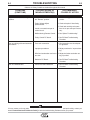
PROBLEMS
(SYMPTOMS)
POSSIBLE AREAS OF
MISADJUSTMENTS(S)
RECOMMENDED
COURSE OF ACTION
PROBLEMS
Output Control not functioning on the 1. Local/Remote switch is in
machine.
the "Remote" position.
2. Faulty Voltage Adjust
potentiometer.
1. Move switch toggle to the "Local"
position.
2. Check and replace if found faulty.
3. Leads or connections open in
control circuit.
3. Check lead continuity and connections for an open and repair if necessary.
4. Malfunctioning Remote Control.
4. See "Options Troubleshooting".
5. Faulty Control PC board.
5. See PC Board Troubleshooting
Procedure.
Poor arc striking with semiautomatic 1. Poor work connection.
wire feeders.
2. Improper procedures.
1. Work connection must be adequate
for application.
2. Adjust procedures for improved starting.
3. Wire feed acceleration too fast or 3. Adjust wire feeder acceleration setting, if provided.
too slow.
Poor arc characteristics
4. Defective PC Board.
4. See PC Board Troubleshooting
Procedure.
1. Control PC Board defective.
1. See PC Board Troubleshooting
Procedure.
CAUTION
If for any reason you do not understand the test procedures or are unable to perform the tests/repairs safely, contact your
Local Lincoln Authorized Field Service Facility for technical troubleshooting assistance before you proceed.
CV-400-I
E-6
E-6
TROUBLESHOOTING
Observe all Safety Guidelines detailed throughout this manual
OPTIONS TROUBLESHOOTING GUIDE
K857 (or other) Remote Output Control
PROBLEMS
(SYMPTOMS)
POSSIBLE AREAS OF
MISADJUSTMENTS(S)
RECOMMENDED
COURSE OF ACTION
PROBLEMS
Output control not functioning on
Remote Control.
1. Local/Remote switch in wrong
position.
1. Place switch in "Remote".
2. Faulty Local/Remote switch.
2. Check and replace if found faulty.
3. Faulty Remote Control potentiometer.
3. Check and replace if found faulty.
4. Leads or connections open in
control circuit.
4. Check all leads and connections,
internal or remote, for continuity;
repair if necessary.
5. Faulty Control PC board.
5. See PC Board Troubleshooting
Procedure.
Voltage Adjust not functioning on the 1. Local/Remote switch in the
machine.
wrong position.
1. Place switch in "Local" position.
2. Faulty Local/Remote switch.
2. Check and replace if found faulty.
3. Faulty Voltage Adjust
potentiometer.
3. Check and replace if found faulty.
CAUTION
If for any reason you do not understand the test procedures or are unable to perform the tests/repairs safely, contact your
Local Lincoln Authorized Field Service Facility for technical troubleshooting assistance before you proceed.
CV-400-I
E-7
TROUBLESHOOTING
Procedure for Replacing PC Boards
E-7
PC BOARD TROUBLESHOOTING
PROCEDURES
WARNING
CONTROL PC BOARD
ELECTRIC SHOCK can kill.
• Have a qualified individual install and
service this equipment.
• Turn the power source input power off
at the disconnect switch before working on this equipment.
• Do not touch electrically hot parts.
--------------------------------------------------------------------Before replacing a PC board which is suspected of
being defective, visually inspect the PC board in question for any electrical or mechanical damage to any of
its components and conductors on the back of the
board.
a. If there is no visible damage to the PC board,
install a new one and see if this remedies the problem. If the problem is remedied, reinstall the old
PC board to see if the problem still exists. If it
does no longer exist with old PC board:
The Control PC Board controls all machine functions
including the thermal protection indicator light and the
Meter PC Board. Most problems, if not caused by
faulty wiring machine misuse, will stem from a faulty
Control PC Board.
Perform the following diagnostic procedure before
replacing the Control PC Board.
1. Turn off the input power at the fuse box.
2. Check for loose connections in the PC Board
plugs, particularly J3.
3. Disconnect the J3 plug from the Control PC Board.
Measure the resistance between the following wire
terminals in the plug:
A) Between wire #200 and wire #201.
1. Check the PC board harness connector pins for
corrosion, contamination, or looseness.
2. Check leads in the plug harness for loose or
intermittent connection.
b. If PC board is visibly damaged electrically, before
possibly subjecting the new PC board to the same
cause of failure, check for possible shorts, opens,
or grounds caused by:
B) Between wire #202 and wire #203.
Both of these resistances should be less than 1 ohm.
If these resistances are not less than 1 ohm, check the
wiring back to the main transformer.
If these voltages are less than 1 ohm, refer to
"Procedure for Replacing PC Boards."
1. Frayed or pinched lead insulation.
METER PC BOARD
2. Poor lead termination, such as a poor contact
or a short to adjacent connection or surface.
When the Meter PC Board malfunctions, first determine
if the rest of the machine functions correctly. If so, then
the problem is in either the harness between the meter
and control boards, or in the meter board itself. Refer
to "Procedure for Replacing PC Boards". As a last
resort, the Control PC Board may have to be replaced.
3. Shorted or open motor leads, or other external
leads.
4. Foreign matter or interference behind the PC
boards.
c. If PC board is visibly damaged mechanically,
inspect for cause, then remedy before installing a
replacement PC board.
If there is damage to the PC board or if replacing
PC board corrects problem, return it to the local
Lincoln Electric Field Service Shop.
CAUTION
If for any reason you do not understand the test procedures or are unable to perform the tests/repairs safely, contact your
Local Lincoln Authorized Field Service Facility for technical troubleshooting assistance before you proceed.
CV-400-I
E-8
TROUBLESHOOTING
E-8
OUTPUT VOLTAGE
The open circuit voltage of the machine should be 10
to 43 volts. If any other condition exists, refer to the
Troubleshooting Guide.
FAULT PROTECTION OPERATION
The overload protection circuit on the PC Board will
cause the CV-400-I meter to display "E60". This protection circuit will reset itself automatically. The short
circuit protection circuit will cause the meter to display
"E00". The CV-400-I power switch must be turned
"OFF" and then "ON" to return the machine to normal
output.
CHECKING SNUBBER CIRCUIT
In case of an SCR malfunction or failure, the snubber
assembly should be checked. Disconnect the input
power to the CV-400-I at the fuse box and remove the
right side of the machine.
1.Visually inspect the snubber PC Board assembly
(located below the Control PC board on the case front
for overheated components or damaged components).
OPTIONAL K857 REMOTE CONTROL
CHECK
Disconnect the remote output control and connect an ohmmeter between pins C and B and rotate the rheostat in the
remote control. The resistance reading should go from zero
to 10K ohms. Repeat with ohmmeter across A and B with
the same results. Connect ohmmeter across A and C. The
reading should be 10K ohms. A lower reading will indicate a
shorted or partially shorted rheostat. A very high reading
will indicate an open rheostat. In either of the last two
cases, replace the rheostat.
CAUTION
If for any reason you do not understand the test procedures or are unable to perform the tests/repairs safely, contact your
Local Lincoln Authorized Field Service Facility for technical troubleshooting assistance before you proceed.
CV-400-I
5
2 3
12
2
3
10
8
6
9
11
1
7
8
2
9
3
2 3
5
6
415V
1
7
4
1
1
5
2 3
12
2
3
10
8
6
9
11
1
7
N.C.
1
2 3
1
9
6
8
2 3
3
2
5
1
7
4
TO S1 LINE SWITCH
PANEL
200V
1
2
9
6
8
2 3
3
2
5
4
7
500V
1
D
4
400V
1
7
4
1
1
1
MAIN TRANSFORMER
TO S1 LINE SWITCH
PANEL
RECONNECT
200/400 INPUT VOLTAGES
RECONNECT
11
1
7
TO S1 LINE SWITCH
2 3
E
F
D
3
5
6
4
1
8
E
9
PANEL
RECONNECT
5
2
2 3
F
7
5
12
2
3
10
8
6
9
440V
10
4
7
1
11
8
5
2
12
TO S1 LINE SWITCH
PANEL
6
3
8
380V
TO S1 LINE SWITCH
9
PANEL
RECONNECT
D
E
RECONNECT
380/500 INPUT VOLTAGES
4
380V
TO S1 LINE SWITCH
PANEL
RECONNECT
*
3
N.B.
F
6
9
s
127V
s
127V
s
58V
58V
s
42V
s
12V
s
12V
s
1
2
3
O1 BOT.
O2 BOT.
O3 BOT.
O3 TOP
42A
O1 TOP
41A
O1
10 TOP
O2 TOP
221
222
223
52A
224
G1
204A
10A
42
50
31A
220V
31B
FAN
33
BREAKER
33A
D4
52
115V
32
CIRCUIT
5A
1
223
224
2
G3
8
1
NC
2A
BREAKER
J4
J3
J2
J1
214
212
5
2
S2
J7
BOARD
P.C.
METER
J7
4 PIN
J1
6 PIN
J4
C1-C4 31,000 MFD EACH
2 PIN
J10
J3
J2
J5
10 PIN
8 PIN
(COMPONENT SIDE OF P. C. BOARD)
CONNECTOR CAVITY NUMBERING SEQUENCE
PER E1537
ELECTRICAL SYMBOLS
(SHOWN IN "VOLTS" POSITION)
N.A.
4
3
209
210
2
208
VOLTS / AMPS
211
3
4
1
6
OF 380/500V MACHINES ONLY.
N.C. TAP LEADS D, E, AND F APPEAR ON THE BOTTOM PRIMARY COILS
FOR 415V, 200/400V, AND 380/500V MACHINES ONLY.
N.B. THIS PERMANENT CONNECTION IS MADE AT THE MAIN TRANSFORMER
CONNECTIONS
CUSTOMER
GROUND
42 VAC
115 VAC
WIRE FEEDER
VOLTMETER
RECEPTACLE
WIRE
FEEDER
M
B
L
K
I
42
A
41
J
N
32
31
D
G
F
E
H
4
77
4
75
76
SWITCH
VOLTMETER
WIRE FEEDER
S3
214A
6
1
CONTROL
CW
21
213A
C
207
376
10K
OUTPUT
N.A.
76
77
377
376
-
-
+
2
276
277
S4
(SHOWN IN LOCAL POSITION)
213
377
213B
213A
LOCAL/REMOTE SWITCH
214B
L1 CHOKE
400 A. 50mV
SHUNT
-
2
275
NC
276
277
224B
214B
219
218
214
213
1
5
2
4
7
3
8
2
1
6
5
N.A. WIRING VIEWED FROM REAR OF POTENTIOMETER
5
206
51
7
3
2
10
6
205
215
201
200
9
202
203
3
4
G1
213B
1
4
J10
J5
224B
P. C. BOARD
G2
204A
J5
CONTROL
213B
7
3
4
222
2
SNUBBER/BYPASS
P.C. BOARD
8
221
204C
224A
CIRCUIT
CB3
31
BREAKER
CB2
L1
THERMOSTAT
SECONDARY
224B
C4
C3
+
C2
+
204C
D5
+
C1
+
R1
220 W
7.5 OHM
204D
204D
G2
41
G3
CIRCUIT
CB1
D1
SCR1
D2
SCR2
D3
SCR3
L8928
6-18-93
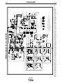
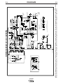
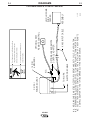
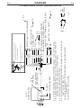
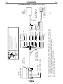
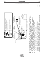
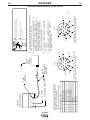
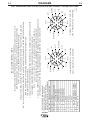
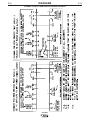
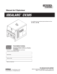
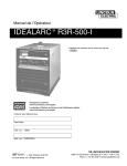
DIAGRAMS
NOTE: This diagram is for reference only. It may not be accurate for all machines covered by this manual. The specific diagram for a particular code is pasted inside
the machine on one of the enclosure panels. If the diagram is illegible, write to the Service Department for a replacement. Give the equipment code number..
TO S1 LINE SWITCH
PANEL
RECONNECT
415 INPUT VOLTAGE
4
220V
TO S1 LINE SWITCH
PANEL
RECONNECT
2
1
L3
W
* TO A SYSTEM GROUND PER
NATIONAL ELECTRICAL CODE.
L2
L1
S1
LINE
SWITCH
V
U
3
RECONNECT
PANEL
224A
INPUT SUPPLY
LINES
220/380/440 INPUT VOLTAGES
8
+
WIRING DIAGRAM CV 400-I (EXPORT)
8
8
8
CV-400-I
8
R2
F-1
F-1
CV-400-I
5
2 3
12
2
3
10
8
9
6
11
1
7
1
5
12
2
8
2 3
10
3
9
6
11
1
7
4
400V
TO S1 LINE SWITCH
PANEL
1
s
127V
s
127V
s
58V
58V
s
42V
s
12V
s
12V
s
1
2
MAIN TRANSFORMER
10
4
7
1
11
8
5
2
12
6
9
3
O1 BOT.
O2 BOT.
O3 BOT.
O3 TOP
42A
O1 TOP
41A
O1
10 TOP
O2 TOP
221
222
223
52A
224
G1
204A
10A
42
50
31A
220V
FAN
BREAKER
33A
D4
52
L1
1
223
224
2
8
1
NC
BREAKER
J4
J3
J2
J1
214
J7
BOARD
P.C.
METER
J7
4 PIN
J1
6 PIN
J4
C1-C4 31,000 MFD EACH
2 PIN
J10
J3
J2
J5
10 PIN
8 PIN
(COMPONENT SIDE OF P. C. BOARD)
CONNECTOR CAVITY NUMBERING SEQUENCE
PER E1537
ELECTRICAL SYMBOLS
(SHOWN IN "VOLTS" POSITION)
N.A.
4
3
210
2
209
VOLTS / AMPS
211
212
5
2
3
4
1
208
42
41
D
CONNECTIONS
CUSTOMER
GROUND
42 VAC
WIRE FEEDER
VOLTMETER
RECEPTACLE
WIRE
FEEDER
M
B
L
K
I
A
J
N
4
6
4
G
F
E
H
6
77
C
75
76
SWITCH
VOLTMETER
WIRE FEEDER
S3
214A
2
1
CW
21
213A
275
S2
10K
376
CONTROL
OUTPUT
N.A.
377
376
76
77
-
-
+
2
207
277
276
S4
(SHOWN IN LOCAL POSITION)
213
377
213B
213A
LOCAL/REMOTE SWITCH
214B
L1 CHOKE
400 A. 50mV
SHUNT
-
1
NC
276
277
224B
214B
219
218
214
213
5
2
4
7
3
8
2
1
6
5
N.A. WIRING VIEWED FROM REAR OF POTENTIOMETER
5
51
7
205
3
2
10
6
206
215
201
200
9
202
203
3
4
G1
213B
1
4
G3
J10
J5
224B
P. C. BOARD
G2
204A
J5
CONTROL
213B
7
3
4
222
2
SNUBBER/BYPASS
P.C. BOARD
8
221
204C
224A
2A
CIRCUIT
CB3
THERMOSTAT
SECONDARY
224B
C4
C3
+
C2
+
204C
D5
+
C1
+
R1
220 W
7.5 OHM
204D
204D
G2
41
G3
CIRCUIT
CB1
D1
SCR1
D2
SCR2
D3
SCR3
L9857
3-10-95H
DIAGRAMS
NOTE: This diagram is for reference only. It may not be accurate for all machines covered by this manual. The specific diagram for a particular code is pasted inside
the machine on one of the enclosure panels. If the diagram is illegible, write to the Service Department for a replacement. Give the equipment code number..
4
230V
TO S1 LINE SWITCH
PANEL
RECONNECT
230/400 INPUT VOLTAGES
RECONNECT
* TO A SYSTEM GROUND PER
NATIONAL ELECTRICAL CODE.
*
2
1
3
L3
L2
L1
S1
LINE
SWITCH
W
V
U
3
RECONNECT
PANEL
224A
INPUT SUPPLY
LINES
+
WIRING DIAGRAM CV 400-I (EUROPE)
R2
F-2
F-2
CV-400-I
-
ELECTRODE CABLE
TO WORK
N.C.
REMOTE CONTROL
OPTIONAL K857
K480 INPUT CABLE
OPTIONAL K864 REMOTE
CONTROL ADAPTER
14 PIN
AMPHENOL
service this machine.
Only qualified persons should install, use or
Before connecting the wire feeder.
using the disconnect switch at the fuse box
Turn off input power to the Welding Power Source
S20662
6-18-93
ASSEMBLY
LN-7/LN-7GMA
WIRE
FEEDER
DIAGRAMS
CONTROL ADAPTER TO THE 14 PIN AMPHENOL OF THE POWER SOURCE.
N.C. USE OF THE K857 REMOTE CONTROL REQUIRES THE INSTALLATION OF A K864 REMOTE
N.B. DIAGRAM SHOWS ELECTRODE POSITIVE. TO CHANGE POLARITY, TURN POWER "OFF",
N.A. WELDING CABLE MUST BE SIZED FOR CURRENT AND DUTY CYCLE OF APPLICATION.
+
POWER SOURCE
CV/CV-I
CAN KILL
SHOCK
ELECTRIC
WARNING
F-3
F-3
CV POWER SOURCE TO AN LN-7 AND K857
CV-400-I
-
ELECTRODE CABLE
TO WORK
K867 UNIVERSAL
ADAPTER PLUG
14 PIN
AMPHENOL
77
76
75
21
32
GND
31
42
41
4
2
SPARE
82
81
service this machine.
MIN.
10K
N.F. NOT PRESENT ON ALL MACHINES
N.E. REFER TO POWER SOURCE INSTRUCTION MANUAL FOR MAXIMUM AUXILIARY
CURRENT DRAW.
RELAY TO CLOSE LEADS 2 & 4.
K867
TO
4
2
REMOTE OUTPUT CONTROL
N.D. FOR WIRE FEEDERS THAT RETURN A SIGNAL FOR WELDING OUTPUT, USE ISOLATION
N.C. INSULATE EACH UNUSED LEAD INDIVIDUALLY.
N.D.
N.C.
S20658
6-18-93
FEEDER
WIRE
TO
N.F.
CONNECTS TO (WORK TERMINAL) OF POWER SOURCE
WIRE FEEDER VOLTMETER CONNECTION
N.B. DIAGRAM SHOWS ELECTRODE POSITIVE. TO CHANGE POLARITY, TURN POWER "OFF",
REVERSE ELECTRODE AND WORK CABLES AT POWER SOURCE.
N.F.
N.E.
POWER SOURCE FRAME CONNECTION
115 VAC
42 VAC
WELDING OUTPUT
CONNECT TOGETHER FOR
NOT USED ON CV/CV-I POWER SOURCES
Only qualified persons should install, use or
N.A. WELDING CABLE MUST BE SIZED FOR CURRENT AND DUTY CYCLE OF APPLICATION.
+
POWER SOURCE
CV/CV-I
CAN KILL
SHOCK
ELECTRIC
Before connecting the wire feeder.
using the disconnect switch at the fuse box
Turn off input power to the Welding Power Source
{
WARNING
F-4
DIAGRAMS
F-4
CV POWER SOURCE TO A K867 UNIVERSAL ADAPTER
CV-400-I
-
ELECTRODE CABLE
TO WORK
K867 UNIVERSAL
ADAPTER PLUG
14 PIN
AMPHENOL
service this machine.
4
21
4
21
N.D.
2
2
75
76
77
75
76
77
GND
GREEN
32
GND
31
32
N.C.
31
41
42
81
82
SPARE
Only qualified persons should install, use or
Before connecting the wire feeder.
using the disconnect switch at the fuse box
Turn off input power to the Welding Power Source
N.D. SPLICE LEADS AND INSULATE.
N.C. INSULATE EACH UNUSED LEAD INDIVIDUALLY.
REVERSE ELECTRODE AND WORK CABLES AT POWER SOURCE.
N.B. DIAGRAM SHOWS ELECTRODE POSITIVE. TO CHANGE POLARITY, TURN POWER "OFF",
N.A. WELDING CABLE MUST BE SIZED FOR CURRENT AND DUTY CYCLE OF APPLICATION.
+
POWER SOURCE
CV/CV-I
CAN KILL
SHOCK
ELECTRIC
WARNING
S20659
6-18-93
K775 OPTIONAL
REMOTE CONTROL
K291 OR K404
INPUT CABLE
LN-7
WIRE
FEEDER
F-5
DIAGRAMS
F-5
CV POWER SOURCE TO A K867 / K775 / LN-7
CV-400-I
+
-
TO WORK
N.D.
LN-25
WIRE FEEDER
CONTROL ADAPTER
OPTIONAL K864 REMOTE
REMOTE CONTROL
OPTIONAL K857
ELECTRODE CABLE
OPTIONAL
K484 JUMPER
PLUG
14 PIN
AMPHENOL
service this machine.
Only qualified persons should install, use or
Before connecting the wire feeder.
using the disconnect switch at the fuse box
Turn off input power to the Welding Power Source
S20661
6-18-93
DIAGRAMS
THE POWER SOURCE WELDING TERMINALS ARE ALWAYS "HOT" WHEN THE K484 JUMPER
TO THE 14 PIN AMPHENOL OF THE K864 REMOTE CONTROL ADAPTER.
IF USING A K857 REMOTE CONTROL,CONNECT THE K484 JUMPER PLUG
OF THE POWER SOURCE IF NO REMOTE CONTROL IS USED.
N.D. CONNECT THE K484 JUMPER PLUG DIRECTLY TO THE 14 PIN AMPHENOL
CONTROL ADAPTER TO THE 14 PIN AMPHENOL OF THE POWER SOURCE.
N.C. USE OF THE K857 REMOTE CONTROL REQUIRES INSTALLATION OF A K864 REMOTE
REVERSE ELECTRODE AND WORK CABLES AT POWER SOURCE.
N.B. DIAGRAM SHOWS ELECTRODE POSITIVE. TO CHANGE POLARITY, TURN POWER "OFF",
N.A. WELDING CABLE MUST BE SIZED FOR CURRENT AND DUTY CYCLE OF APPLICATION.
N.C.
POWER SOURCE
CV/CV-I
CAN KILL
SHOCK
ELECTRIC
WARNING
F-6
F-6
CV POWER SOURCE TO AN LN-25
CV-400-I
+
-
TO WORK
N.C.
ELECTRODE CABLE
WITH K444-1 OPTION
LN-25
WIRE FEEDER
CONTROL ADAPTER
OPTIONAL K864 REMOTE
OPTIONAL
K484 JUMPER
PLUG
14 PIN
AMPHENOL
service this machine.
Only qualified persons should install, use or
Before connecting the wire feeder.
using the disconnect switch at the fuse box
Turn off input power to the Welding Power Source
REMOTE CONTROL ADAPTER. SWITCH THE POWER SOURCE "LOCAL/REMOTE" SWITCH TO REMOTE.
N.D. THE POWER SOURCE TERMINALS ARE ALWAYS "HOT" WHEN THE K484 JUMPER
PLUG KIT IS INSTALLED.
N.A. WELDING CABLE MUST BE SIZED FOR CURRENT AND DUTY CYCLE OF APPLICATION.
N.B. DIAGRAM SHOWS ELECTRODE POSITIVE. TO CHANGE POLARITY, TURN POWER "OFF",
REVERSE ELECTRODE AND WORK CABLES AT POWER SOURCE, SWITCH LN-25 POLARITY SWITCH.
N.C. CONNECT THE K484 JUMPER PLUG TO THE 14 PIN RECEPTACLE OF THE
K864 REMOTE CONTROL ADAPTER. CONNECT THE 6 PIN PLUG FROM THE
LN-25 (WITH K444-1 OPTION) TO THE 6 PIN RECEPTACLE OF THE K864
N.D.
CV/CV-I
POWER SOURCE
CAN KILL
SHOCK
ELECTRIC
WARNING
CV/CV-I POWER SOURCE TO LN-25 WITH K444-1 OPTION CONNECTION DIAGRAM
DIAGRAMS
S20663
6-18-93
F-7
F-7
CV POWER SOURCE TO AN LN-25 / K444-1
CV-400-I
-
TRIGGER CIRCUIT
TRIGGER CIRCUIT
OUTPUT CONTROL
OUTPUT CONTROL
OUTPUT CONTROL
WORK
42V AC
42V AC
LEAD
2
4
77
76
75
21
41
42
PIN
C
D
E
F
G
H
I
K
FUNCTION
(SEE APPROPRIATE WIRING DIAGRAM)
N.D.
E=77
AND 14-PIN CABLE PLUG, REAR VIEW
CAN KILL
SHOCK
ELECTRIC
service this machine.
Only qualified persons should install, use or
Power Source before connecting the wire feeder.
Turn off (0) the power switch on the Welding
G=75
H=21
I=41
F=76
K=42
E=77
D=4
C=2
14-SOCKET BOX RECEPTACLE, REAR VIEW
AND 14-PIN CABLE PLUG, FRONT VIEW
G=75
H=21
I=41
TO "REMOTE" POSITION.
SET POWER SOURCE CONTROL SWITCH
N.D. IF USING K589-1, REMOTE CONTROL KIT,
ON CABLE.
N.C. PINS NOT LISTED ARE NOT CONNECTED
SOURCE TO PROPER POLARITY.
VOLTMETER POLARITY SWITCH ON POWER
POWER SOURCE AND SET WIRE FEEDER
REVERSE ELECTRODE AND WORK CABLES AT
CHANGE POLARITY, TURN POWER "OFF",
N.B. DIAGRAM SHOWS ELECTRODE POSITIVE. TO
AND DUTY CYCLE OF APPLICATION.
N.A. WELDING CABLE MUST BE SIZED FOR CURRENT
14-SOCKET BOX RECEPTACLE, FRONT VIEW
D=4
C=2
K=42
F=76
LN-742
WIRE
FEEDER
LN-742
INPUT CABLE
ASSEMBLY
14 PIN
AMPHENOL
ELECTRODE CABLE
TO WORK
FUNCTIONS ARE LISTED FOR REFERENCE
ONLY AND EACH MAY OR MAY NOT BE
PRESENT IN YOUR EQUIPMENT.
+
POWER SOURCE
LINCOLN
WARNING
1-28-94
S20409
F-8
DIAGRAMS
F-8
LINCOLN POWER SOURCE TO AN LN-742
TURN THE POWER SWITCH OF THE WELDING POWER SOURCE OFF BEFORE INSTALLING
MAY OR MAY NOT BE ISOLATED, INDEPENDENT CIRCUITS INSIDE THE WELDER.
115V AC (31, 32), 42V AC (41, 42), 24V AC (SPARE) AND TRIGGER CIRCUIT (2, 4)
CV-400-I
31
J
82
42
81
SPARE
L
M
N
K
42V AC
41
I
24V AC
WELDING MODE CONTROL
WELDING MODE CONTROL
42V AC
115V AC
WORK
21
H
E
OUTPUT CONTROL
D
OUTPUT CONTROL
4
77
C
76
OUTPUT CONTROL
2
75
TRIGGER CIRCUIT
GND
B
F
CHASSIS CONNECTION
TRIGGER CIRCUIT
32
A
G
115V AC
LEAD
PIN
STANDARD FUNCTION
MAY NOT BE PRESENT IN YOUR EQUIPMENT.
REFERENCE ONLY AND EACH MAY OR
THESE FUNCTIONS ARE LISTED FOR
E=77
M=81
F=76
G=75
N=SPARE
H=21
I=41
J=31
AND 14-PIN CABLE PLUG, REAR VIEW
14-PIN BOX RECEPTACLE, FRONT VIEW
D=4
C=2
L=82
B=GND
A=32
K=42
F=76
M=81
K=42
E=77
D=4
L=82
C=2
B=GND
A=32
S19386
3-16-90
AND 14-PIN CABLE PLUG, FRONT VIEW
14-PIN BOX RECEPTACLE, REAR VIEW
G=75
H=21
N=SPARE
I=41
J=31
IN THE UNIVERSAL ADAPTER. THE INSULATING METHOD MUST BE RATED FOR 120V AC OR GREATER.
USE LUG, CRIMP SPLICE OR SOLDER CONNECTIONS AS REQUIRED AND INSULATE EACH USED AND UNUSED LEAD
NOTE:
THE STANDARD CONNECTOR PIN DESIGNATIONS AND FUNCTIONS ARE SHOWN BELOW.
CONSULT THE APPROPRIATE EQUIPMENT WIRING DIAGRAMS FOR THE CONNECTIONS TO UNIVERSAL ADAPTER.
THIS ADAPTER TO WIRE FEEDER CABLE.
(SEE APPROPRIATE WIRING DIAGRAM)
3.
2.
1.
NOT ALL CIRCUITS ARE PRESENT IN EVERY POWER SOURCE, NOR ARE THEY REQUIRED FOR PROPER WIRE FEEDER OPERATION.
CONSULT THE WIRING DIAGRAM OF THE POWER SOURCE AND WIRE FEEDER THIS ADAPTER WILL BE USED WITH.
TO ANY OF THE 14 CIRCUITS PRESENT IN THE WIRE FEEDER RECEPTACLE.
WIRE FEEDER RECEPTACLE. IT IS DESIGNED TO ALLOW THE USER TO MAKE CONNECTIONS
THIS CONNECTOR IS MEANT TO BE USED WITH LINCOLN POWER SOURCES WHICH HAVE A 14-PIN
INSTALLATION INSTRUCTIONS
F-9
DIAGRAMS
F-9
K867 UNIVERSAL ADAPTER INSTALLATION AND CONNECTION INSTRUCTIONS
F-10
F-10
DIAGRAMS
TWIST-MATE CABLE PLUG INSTALLATION INSTRUCTIONS
TWIST-MATE WELDING CABLE PLUG INSTALLATION INSTRUCTIONS
TURN THE POWER SWITCH OF THE WELDING POWER
SOURCE "OFF" BEFORE INSTALLING PLUGS ON CABLES
OR WHEN CONNECTING OR DISCONNECTING PLUGS TO
WELDING POWER SOURCE.
1.
CHECK THAT THE CONNECTOR BOOT IS MARKED FOR THE
APPROPRIATE CABLE SIZE PER TABLE BELOW; AND
SKIN CABLE JACKET TO LENGTH SPECIFIED:
BOOT MARKING
AMERICAN (EUROPEAN) RANGE
#2-#1
35-50
50-70
( 35-50
1/0-2/0
2/0-3/0
70-95
2.
CABLE SIZE
CABLE SKIN LENGTH
2
1 INCH (25.4mm)
mm )
( 50-70
( 70-95
2
mm )
2
mm )
1 INCH (25.4mm)
1.5 INCH (38.1mm)
If necessary, trim cable end of boot at groove(s) to match cable
diameter. Boot must fit tightly enough to seal around outside
diameter of cable. NOTE: Some boots are designed to accommodate
different cable diameters without trimming. These boots do not
have grooves at the cable end. Soap or other non petroleum
based lubricant will help to slide the boot over the cable.
3.
BOOT
Slide rubber boot onto cable end.
WELDING CABLE
SEE
ABOVE
TRIM
4.
Slide the copper tube into the brass plug.
5.
Insert cable into copper tube.
SET SCREW
(70-95 size may
have 2 set
screws)
BRASS PLUG
COPPER TUBE
Slide rubber boot over brass plug. The rubber boot must be
positioned to completely cover all electrical surfaces after
the plug is locked into the receptacle.
CV-400-I
S18737
7.
Tighten set screw(s) to collapse copper tube. Screw(s)
must apply firm pressure against welding cable. The top of the
set screw(s) will be nearly flush or below the surface of the
brass plug after tightening.
9-20-91J
6.
F-11
DIAGRAMS
CONNECTION OF NON-LINCOLN WIRE FEEDERS
CV-400-I
F-11
CV-400-I
N.A.
17.25 (438) (CENTERED)
19.20 (487)
19.65 (499)
20.05 (509)
1.68
30.95
(786)
N.B.
1.38
(35)
6.20 (157)
N.A.
21.50 (546)
24.75
(628)
(42.7)
3.61 (91)
FOUR SLOTS IN BASE FOR MOUNTING
WELDER DOWN USING 5/16 SCREWS
12.60 (320)
N.B. HANDLE CONFIGURATION ON EARLIER MODELS.
N.A.
41.58 (1056)
23.62 (600)
26.00 (660)
1.00 (25.4)
.28
(7.0)
N.A.
3.90 (99)
11.99 (304)
5-18-90J
M15665
F-12
DIAGRAMS
F-12
DIMENSION PRINT
Now Available...12th Edition
The Procedure Handbook of Arc Welding
New Lessons in Arc Welding
This printing will go fast so don’t delay. Place your
order now using the coupon below.
Lessons, simply written, cover manipulatory techniques;
machine and electrode characteristics; related subjects,
such as distortion; and supplemental information on arc
welding applications, speeds and costs. Practice materials,
exercises, questions and answers are suggested for each
lesson.
The hardbound book contains over 750 pages of welding
information, techniques and procedures. Much of this material
has never been included in any other book.
528 pages, well illustrated, 6” x 9” size, bound in simulated,
gold embossed leather.
$5.00 postage paid U.S.A. Mainland
With over 500,000 copies of previous editions published
since 1933, the Procedure Handbook is considered by many to
be the “Bible” of the arc welding industry.
A must for all welders, supervisors, engineers and
designers. Many welding instructors will want to use the book
as a reference for all students by taking advantage of the low
quantity discount prices which include shipping by
4th class parcel post.
$15.00 postage paid U.S.A. Mainland
How To Read Shop Drawings
The book contains the latest information and application
data on the American Welding Society Standard Welding
Symbols. Detailed discussion tells how engineers and
draftsmen use the “short-cut” language of symbols to pass
on assembly and welding information to shop personnel.
Practical exercises and examples develop the reader’s ability
to visualize mechanically drawn objects as they will appear
in their assembled form.
Need Welding Training?
The Lincoln Electric Company operates the oldest and
most respected Arc Welding School in the United States at its
corporate headquarters in Cleveland, Ohio. Over 100,000 students have graduated. Tuition is low and the training is
“hands on”
For details write:
Lincoln Welding School
22801 St. Clair Ave.
Cleveland, Ohio 44117-1199.
and ask for bulletin ED-80 or call 216-383-2259 and ask for the
Welding School Registrar.
187 pages with more than 100 illustrations. Size 8-1/2” x 11”
Durable, cloth-covered board binding.
$4.50 postage paid U.S.A. Mainland
Lincoln Welding School
BASIC COURSE
5 weeks of fundamentals
$700.00
There is a 10% discount on all orders of $50.00 or more for shipment at one time to one location.
Orders of $50 or less before discount or orders outside of North America must be prepaid with charge, check or money order in U.S. Funds Only.
Prices include shipment by 4 th Class Book Rate for U.S.A. Mainland Only. Please allow up to 4 weeks for delivery.
UPS Shipping for North America Only. All prepaid orders that request UPS shipment please add:
$5.00
For order value up to $49.99
$10.00
For order value between $50.00 & $99.99
$15.00
For order value between $100.00 & $149.00
For North America invoiced orders over $50.00 & credit card orders, if UPS is requested, it will be invoiced or charged to you at cost.
Outside U.S.A. Mainland order must be prepaid in U.S. Funds. Please add $2.00 per book for surface mail or $15.00 per book for air parcel post shipment.
METHOD OF PAYMENT: (Sorry, No C.O.D. Orders)
Name:
_______________________________________________
CHECK ONE:
Please Invoice (only if order is over $50.00)
Check or Money Order Enclosed, U.S. Funds only
Credit Card MasterCard
VISA
Address:
_______________________________________________
_______________________________________________
Telephone: _______________________________________________
®
®
Account No.
|_|_|_|_|_|_|_|_|_|_|_|_|_|_|_|_|_|_|_|_|_|
AMERICAN EXPRESS
MasterCard
Exp Date
|_|_|
|_|_|
Month
Year
Signature as it appears on Charge Card:
______________________
AMERICAN EXPRESS
USE THIS FORM TO ORDER:
BOOKS OR FREE INFORMATIVE CATALOGS
Lincoln Welding School
(ED-80)
Seminar Information
(ED-45)
Educational Video Information
(ED-93)
James F. Lincoln Arc Welding
Foundation Book Information
(JFLF-515)
Order from:
BOOK DIVISION, The Lincoln Electric Company, 22801 St. Clair Avenue, Cleveland, Ohio 44117-1199
Telephone: 216-383-2211 or, for fastest service, FAX this completed form to: 216-361-5901.
Titles:
Price
New Lessons in Arc Welding
$5.00
Procedure Handbook “Twelfth Edition”
$15.00
How to Read Shop Drawings
$4.50
Incentive Management
$5.00
A New Approach to Industrial Economics $5.00
The American Century of John C. Lincoln $5.00
Welding Preheat Calculator
$3.00
Pipe Welding Charts
$4.50
Code
L
PH
H
IM
NA
AC
WC-8
ED-89
Quantity
SUB TOTAL
Additional Shipping Costs if any
TOTAL COST
Cost
WARNING
Spanish
AVISO DE
PRECAUCION
French
ATTENTION
German
WARNUNG
Portuguese
ATENÇÃO
● Do not touch electrically live parts or
● Keep flammable materials away.
● Wear eye, ear and body protection.
● Mantenga el material combustible
● Protéjase los ojos, los oídos y el
electrode with skin or wet clothing.
● Insulate yourself from work and
ground.
● No toque las partes o los electrodos
bajo carga con la piel o ropa mojada.
● Aislese del trabajo y de la tierra.
● Ne laissez ni la peau ni des vête-
ments mouillés entrer en contact
avec des pièces sous tension.
● Isolez-vous du travail et de la terre.
● Berühren Sie keine stromführenden
Teile oder Elektroden mit Ihrem
Körper oder feuchter Kleidung!
● Isolieren Sie sich von den
Elektroden und dem Erdboden!
● Não toque partes elétricas e elec-
trodos com a pele ou roupa molhada.
● Isole-se da peça e terra.
fuera del área de trabajo.
● Gardez à l’écart de tout matériel
inflammable.
● Entfernen Sie brennbarres Material!
cuerpo.
● Protégez vos yeux, vos oreilles et
votre corps.
● Tragen Sie Augen-, Ohren- und Kör-
perschutz!
● Mantenha inflamáveis bem guarda-
dos.
● Use proteção para a vista, ouvido e
corpo.
Japanese
Chinese
Korean
Arabic
READ AND UNDERSTAND THE MANUFACTURER’S INSTRUCTION FOR THIS EQUIPMENT AND THE CONSUMABLES TO BE
USED AND FOLLOW YOUR EMPLOYER’S SAFETY PRACTICES.
SE RECOMIENDA LEER Y ENTENDER LAS INSTRUCCIONES DEL FABRICANTE PARA EL USO DE ESTE EQUIPO Y LOS
CONSUMIBLES QUE VA A UTILIZAR, SIGA LAS MEDIDAS DE SEGURIDAD DE SU SUPERVISOR.
LISEZ ET COMPRENEZ LES INSTRUCTIONS DU FABRICANT EN CE QUI REGARDE CET EQUIPMENT ET LES PRODUITS A
ETRE EMPLOYES ET SUIVEZ LES PROCEDURES DE SECURITE DE VOTRE EMPLOYEUR.
LESEN SIE UND BEFOLGEN SIE DIE BETRIEBSANLEITUNG DER ANLAGE UND DEN ELEKTRODENEINSATZ DES HERSTELLERS. DIE UNFALLVERHÜTUNGSVORSCHRIFTEN DES ARBEITGEBERS SIND EBENFALLS ZU BEACHTEN.
● Keep your head out of fumes.
● Use ventilation or exhaust to
● Turn power off before servicing.
● Do not operate with panel open or
guards off.
remove fumes from breathing zone.
● Los humos fuera de la zona de res-
piración.
● Mantenga la cabeza fuera de los
humos. Utilice ventilación o
aspiración para gases.
● Gardez la tête à l’écart des fumées.
● Utilisez un ventilateur ou un aspira-
● Desconectar el cable de ali-
mentación de poder de la máquina
antes de iniciar cualquier servicio.
● Débranchez le courant avant l’entre-
tien.
teur pour ôter les fumées des zones
de travail.
● Vermeiden Sie das Einatmen von
Schweibrauch!
● Sorgen Sie für gute Be- und
Entlüftung des Arbeitsplatzes!
● Mantenha seu rosto da fumaça.
● Use ventilação e exhaustão para
remover fumo da zona respiratória.
● Strom vor Wartungsarbeiten
● No operar con panel abierto o
guardas quitadas.
● N’opérez pas avec les panneaux
ouverts ou avec les dispositifs de
protection enlevés.
● Anlage nie ohne Schutzgehäuse
abschalten! (Netzstrom völlig öffnen; Maschine anhalten!)
oder Innenschutzverkleidung in
Betrieb setzen!
● Não opere com as tampas removidas.
● Desligue a corrente antes de fazer
● Mantenha-se afastado das partes
serviço.
● Não toque as partes elétricas nuas.
● Não opere com os paineis abertos
moventes.
ou guardas removidas.
WARNING
Spanish
AVISO DE
PRECAUCION
French
ATTENTION
German
WARNUNG
Portuguese
ATENÇÃO
Japanese
Chinese
Korean
Arabic
LEIA E COMPREENDA AS INSTRUÇÕES DO FABRICANTE PARA ESTE EQUIPAMENTO E AS PARTES DE USO, E SIGA AS
PRÁTICAS DE SEGURANÇA DO EMPREGADOR.
• World's Leader in Welding and Cutting Products •
• Sales and Service through Subsidiaries and Distributors Worldwide •
Cleveland, Ohio 44117-1199 U.S.A. TEL: 216.481.8100 FAX: 216.486.1751 WEB SITE: www.lincolnelectric.com