1
READ AND UNDERSTAND THESE INSTRUCTIONS BEFORE INSTALLING FIXTURE
This fixture is intended for installation in accordance with the National Electrical Code and local regulations. To
assure full compliance with local codes and regulations, check with your local electrical inspector before
installation. To prevent electric shock, turn off electricity at fuse box before proceeding.
Retain these instructions for maintenance reference.
INSTRUCTION SHEET NO.
IS: AUX-E
Page 1 of 2
A0504
INSTRUCTIONS FOR H.I.D. FRAME-IN KITS AND FINISHING SECTIONS WITH OPTIONAL
AUXILIARY AND EMERGENCY LIGHTING
CAUTION: (RISK OF FIRE) DO NOT INSTALL INSULATION ABOVE NOR WITHIN 3 INCHES (76mm) OF ANY
PART OF THE LUMINAIRE (LIGHTING FIXTURE)
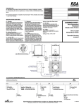
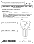
Installing 120V Auxiliary Lampholder onto Reflector
120V AUXILIARY
LAMPHOLDER
(NOTE: For Emergency Lighting applications, use same Auxiliary
Lampholder Accessory without Auxiliary Lighting Control.)
1.
2.
3.
NUT
4.
5.
REFLECTOR
6.
Remove NUT from end of AUXILIARY LAMPHOLDER ASSEMBLY.
Insert threaded end of of AUXILIARY LAMPHOLDER ASSEMBLY into
hole in REFLECTOR.
Secure AUXILIARY LAMPHOLDER ASSEMBLY on inside of
REFLECTOR with NUT.
Some REFLECTORS are provided with a threaded insert. In these
cases, simply screw end of AUXILIARY LAMPHOLDER ASSEMBLY
directly into threaded insert, and discard NUT.
Follow directions included with Frame-in Kit and Trim to complete
installation.
Refer to REFLECTOR labeling for correct wattage information installing
auxiliary lamp.
120V Tungsten Halogen Lamp, D.C. Bayonet Base (not provided).
Refer to labeling on Frame and Trim for correct lamp and wattage
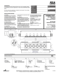
AUXILIARY LIGHTING WIRING DIAGRAM FOR
METAL HALIDE MAGNETIC BALLASTS
(120V/277V DUAL TAP)
THERMAL PROTECTOR
120V/277V
MAGNETIC
BALLAST
AUXILIARY
LIGHTING
CONTROL
CONNECT BLUE WIRE WITH
CONNECTOR TO APPROPRIATE
120V (BLK) OR 277V (RED)
BALLAST LEAD WITH
CONNECTOR
SEE OPPOSITE SIDE FOR ELECTRONIC
BALLAST WIRING DIAGRAMS
A
COMPANY
631 Airport Road, Fall River, MA 02720
READ AND UNDERSTAND THESE INSTRUCTIONS BEFORE INSTALLING FIXTURE
This fixture is intended for installation in accordance with the National Electrical Code and local regulations. To
assure full compliance with local codes and regulations, check with your local electrical inspector before
installation. To prevent electric shock, turn off electricity at fuse box before proceeding.
Retain these instructions for maintenance reference.
INSTRUCTION SHEET NO.
IS: AUX-E
Page 2 of 2
A0504
INSTRUCTIONS FOR H.I.D. FRAME-IN KITS AND FINISHING SECTIONS WITH OPTIONAL
AUXILIARY AND EMERGENCY LIGHTING
CAUTION: (RISK OF FIRE) DO NOT INSTALL INSULATION ABOVE NOR WITHIN 3 INCHES (76mm) OF ANY
PART OF THE LUMINAIRE (LIGHTING FIXTURE)
120V ELECTRONIC
H.I.D. BALLAST
AUXILIARY LIGHTING WIRING DIAGRAM FOR
120V METAL HALIDE ELECTRONIC BALLAST
AUXILIARY LIGHTING
CONTROL
THERMAL PROTECTOR
277V ELECTRONIC
H.I.D. BALLAST
AUXILIARY LIGHTING WIRING DIAGRAM FOR
277V METAL HALIDE ELECTRONIC BALLAST
THERMAL PROTECTOR
AUXILIARY LIGHTING
CONTROL
A
COMPANY
631 Airport Road, Fall River, MA 02720