Transcript
READ AND UNDERSTAND THESE INSTRUCTIONS BEFORE INSTALLING LUMINAIRE
INSTRUCTION SHEET NO.
This luminaire is intended for installation in accordance with the National Electrical Code and local regulations.
To assure full compliance with local codes and regulations, check with your local electrical inspector before
installation. To prevent electric shock, turn off electricity at fuse box before proceeding.
IS:CTC
Retain these instructions for maintenance reference.
A0504
Page 1 of 1
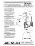
INSTRUCTION SHEET FOR ASSEMBLY AND INSTALLATION OF 9”,12”&16” PENDALYTE™ SERIES
CLOSE TO CEILING MOUNT.
Note: This instruction sheet covers several luminaire styles. Powerhead assembly, lamp type, and reflector style
may vary slightly from that shown, although installation is the same.
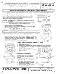
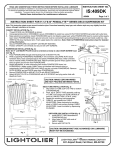
CANOPY INSTALLATION (fig. 1):
1. Attach POWERHEAD ASSEMBLY to CANOPY using 8-32 SCREWS.
2. Using appropriate slots in CROSSBAR, secure CROSSBAR to outlet box using OUTLET BOX SCREWS (provided with
outlet box).
3. Make electrical connections: black POWERHEAD lead to hot (black) supply lead; white POWERHEAD lead to neutral
(white) supply lead. Green POWERHEAD lead is ground wire and must be connected to grounding terminal or ground
lead inside outlet box. Use WIRE NUTS (local hardware item). Push supply leads into outlet box. Note: Refer to
POWERHEAD instruction sheet for detailed wiring information.
4. Thread STUDS into outer holes on CROSSBAR.
5. Attach CANOPY/POWERHEAD ASEMBLY by placing over STUDS and securing with CAP SCREWS.
CROSSBAR
OUTLET
BOX
CAUTION: MAKE CERTAIN WIRES ARE NOT PINCHED
BETWEEN PARTS.
8-32 SCREWS
STUDS
WIRENUTS
CANOPY
CAP
SCREWS
POWERHEAD
ASSEMBLY
CAUTION: MAXIMUM WATTAGE AS MARKED ON
LUMINAIRE MUST NOT BE EXCEEDED.
Fig. 1
A
COMPANY
631 Airport Road, Fall River, MA 02720