1
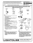
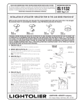
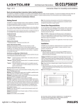
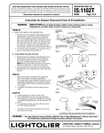
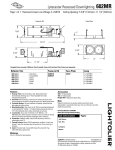
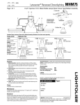
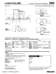
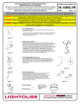
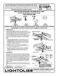
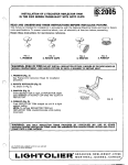
READ AND UNDERSTAND THESE INSTRUCTIONS
BEFORE INSTALLING LUMINAIRE.
INSTRUCTION SHEET NO.
This luminaire is intended for installation in accordance with the National Electrical Code and local regulations.
To assure full compliance with local codes and regulations, check with your local electrical inspector before
installation. To prevent electric shock, turn off electricity at main power supply before proceeding.
Retain these instructions for maintenance reference.
IS:2000LVRE1
Page 1 of 2
A0607
INSTALLATION PROCEDURE FOR: LYTECASTER® 2000LVRE1 LOW VOLTAGE REMODELER KIT
CAUTION: USE ONLY WITH REFLECTOR TRIMS PROVIDED BY LIGHTOLIER.
USE OF OTHER MANUFACTURER’S TRIMS MAY VOID THE
UNDERWRITERS LABORATORIES LISTING AND COULD CONSTITUTE A FIRE HAZARD.
CAUTION: BEFORE INSTALLING FRAME-IN KIT AND REFLECTOR TRIM, READ ALL MARKINGS ON FRAME-IN KIT AND
REFLECTOR TO
DETERMINE LAMP WATTAGE AND TYPE APPLICABLE FOR YOUR INSTALLATION.
WARNING: (RISK OF FIRE) DO NOT INSTALL INSULATION WITHIN 3” OF FIXTURE SIDES OR WIRING COMPARTMENT, NOR ABOVE
FIXTURE IN SUCH A MANNER SO AS TO ENTRAP HEAT.
1. CUT OPENING (Fig. A)
Use aperture sticker provided as a template to cut a hole in the ceiling. Cut to
outside edge of sticker.
* Lightolier also offers a hole cutter (HC-356) that can be purchased separately to
assist with quick, clean trim installations. In this case, follow the hole cutting
directions supplied with HC-356.
Figure A
2. WIRE IN & PUSH THRU
Figure B
Wire to SUPPLY LEADS. (For Cable, use built in CABLE CLAMP in J-BOX).
WHITE FIXTURE LEAD to NEUTRAL SUPPLY LEAD. BLACK FIXTURE LEAD to
HOT SUPPLY LEAD (120V). GREEN AND BARE FIXTURE LEAD WIRE TO
SUPPLY GROUND. Use wirenuts (local hardware item). Place all electrical
connections in J-Box. Attach J-BOX cover onto J-BOX. For flexible CONDUIT, use
90° connector (not supplied) or 3/8” SPRING CONNECTOR (provided). If 3/8”
SPRING CONNECTOR is used, place J-BOX and TRANSFORMER ASSEMBLY
onto ceiling, attach CONNECTOR to CONDUIT and push into one of the 7/8” dia.
knock out holes in J-BOX. Pull J-BOX and TRANSFORMER ASSEMBLY toward
ceiling opening (as shown in Figure B) and complete wiring.
Figure C
3. ATTACH MOUNTING RING (Fig. D)
Push MOUNTING RING into opening until FLANGE sits against ceiling.
Slide MOUNTING STRAPS down to trap ceiling thickness and then bend up
to secure (Fig. E). Make sure “J-BOX” SLOT on REMODELER RING is in a
position that will ensure enough space above ceiling for J-BOX to sit flat
against ceiling.
Figure D
Figure E
4. ATTACH J-BOX (Fig. E)
Insert J-BOX MOUNTING STRAP between the ceiling material and MOUNTING RING and through the
“J-BOX” SLOT on the MOUNTING RING. Pull the STRAP until the J-BOX PLATE sits flat on the
ceiling with the feet over the edge of the ceiling thickness. Bend J-BOX PLATE MOUNTING STRAP
up to secure. Make sure J-BOX PLATE is securely attached to the ceiling and the J-BOX is in the
shown position.
Figure F
5. SNAP-ON (Fig.G)
→
6. PUSH-UP (Fig. H)
SEE SEPARATE
REFLECTOR TRIM
INSTRUCTION
SHEETS
Figure G
Figure H
A
COMPANY
631 Airport Road, Fall River, MA 02720
INSTRUCTION SHEET NO.
INSTALLATION PROCEDURE FOR:
IS:2000LVRE1
Lytecaster® 2000LVRE1 Low Voltage Frame- In Kit
A0607
Page 2 of 2
7. LAMPING (Fig. J)
1. Make sure that power is OFF when lamping or relamping. Remove LAMP RING
from SOCKET CUP by pulling straight down.
2. Insert LAMP (MR-16 bulb) between LAMP SPRINGS until face of bulb sits
firmly on GLASS LAMP GUARD (Figure J).
3. Attach SOCKET to bi-pin prongs on LAMP.
4. Insert LAMP RING with LAMP and GLASS LAMP GUARD back into SOCKET
CUP.
NOTE: 1. LOW VOLTAGE FIXTURES should be dimmed only with special
dimmers intended specifically for that purpose. Use Lightolier Lytemode,
Scenist, Crescendo VA, Neptune VA, Precision VA, Easyset VA, Sunrise VA,
Radiant VA or equivalent products by others or variable autotransformers or
electronic dimmers intended for use with low voltage fixtures. 2. Low voltage
fixtures may produce audible sound when used with dimmers, which may be
objectional in acoustically critical areas.
8. ADJUSTMENT (Fig. K)
1. For vertical adjustment, insert blade of screwdriver into the open slot of YOKE.
2. Using Screwdriver as a lever, tilt the entire LAMP HOLDER to the desired
angle.
3. For horizontal adjustment, rotate the LAMP HOLDER.
A
COMPANY
631 Airport Road, Fall River, MA 02720