1
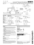
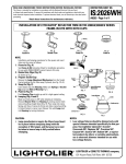
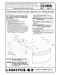
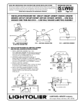
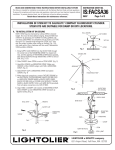
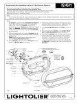
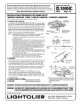
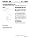
READ AND UNDERSTAND THESE INSTRUCTIONS BEFORE INSTALLING FIXTURE.
This fixture is intended for installation in accordance with the National Electrical Code and local or Federal
code specifications. To assure full compliance with codes and regulations, check with your local electrical
inspector before installation. To prevent electrical shock, turn off electricity at fuse box before proceeding.
INSTRUCTION SHEET NO.
IS:1102T
E0403
Retain these instructions for maintenance reference.
Page 1 of 2
Instructions for Compact Fluorescent Frame-In Kit Installation
WARNING – (RISK OF FIRE) Do not install insulation within 3 inches of fixture sides or wiring
compartments, nor above fixture in such a manner as to entrap heat.
FRAME-IN
A. WOOD JOIST/METAL STUD CONSTRUCTION
1. Position Frame-In Kit opening.* Mounting bars can be
repositioned to narrow side of frame if required to
locate fixture opening as desired. Extend mounting
bars, line up bottom edge of bars with bottom of wood
joist/metal stud and nail in place. For metal stud (Fig.
A2), fasten with machine screws through holes in the
mounting bars. Locking screws are provided to lock
mounting bars in place once positioned properly (Fig. A).
2. For multiple fixture installations, use centered slots as
guides to align adjacent fixture (Fig. A).
ADJUSTABLE
MOUNTING e
BARS
LOCKING SCREW
up
MOUNTING
FRAME
LINE UP BOTTOM EDGE
WITH BOTTOM OF WOOD
JOIST
CENTERING
SLOTS
Fig. A
B. SUSPENDED CEILING SYSTEM
MOUNTING BAR
1. Position Frame-In Kit opening.* Mounting bars can be
repositioned to narrow side of frame if required to
locate fixture opening as desired. Extend mounting
bars, until notched opening fits on top of T-Bar.
(NOTE: Make certain that the bottom of the mounting
frame is no higher than 1” above the ceiling line).
2. Lock mounting bars by bending tab underneath T-Bar
bead (Fig. B1), or by using screws for round T-Bar bead
(Fig. B2).
Fig. A1
MOUNTING BAR
Fig. A2
1-1/2” MAX.
WIRE-IN
1. White fixture leads to neutral (white) supply lead.
Black fixture leads to hot (black) supply leads.
Bare copper and/or green insulated wire(s) must all be
connected to supply ground. Use wirenuts for splices
(local hardware item). Place all electrical connections
in the J-Box.
2. For ROMEX or BX cable use built-in cable clamp in
J-Box.
ADJUSTABLE
MOUNTING
BARS
B1
NOTCHED B2
OPENING
1” MAX.
T-BAR
Fig. B
CLOSE-IN
1. Install plasterboard or other dry type ceiling.
2. Hole in plasterboard can be cut by using mounting
frame opening as a guide (Fig. C) (make sure roto clips
are rotated counterclockwise out of the hole area, see
Fig. D).
3. For wet plaster ceilings, use plaster Ring Accessory
No. 1961 (ordered separately).
* See Page 2 for Frame-In Kit installation when using
wall washer trim (1135).
ROTO CLIP
MOUNTING
FRAME
Fig. C
Fig. D
CEILING MATERIAL
See Reflector Trim Instruction Sheet for Trim Installation
WARNING – Use only reflector trims provided by Lightolier. Use of other Manufacturers’ reflector trims voids
the Underwriters Laboratories listing and could constitute a fire hazard.
®
LIGHTOLIER a GENLYTE THOMAS company.
631 Airport Road, Fall River, MA 02720
READ AND UNDERSTAND THESE INSTRUCTIONS BEFORE INSTALLING FIXTURE.
INSTRUCTION SHEET NO.
This fixture is intended for installation in accordance with the National Electrical Code and local or Federal
code specifications. To assure full compliance with codes and regulations, check with your local electrical
inspector before installation. To prevent electrical shock, turn off electricity at fuse box before proceeding.
IS:1102T
E0403
Retain these instructions for maintenance reference.
Page 2 of 2
BALLAST REPLACEMENT (MAGNETIC VERSION SHOWN)
1. TURN OFF POWER.
2. Remove Reflector Trim from ceiling (see Reflector Trim instructions).
3. Remove Ballast assembly by lifting spring on top of J-Box and
pulling ballast outward (Fig. E).
4. Disconnect all wiring.
5. Replace Ballast on J-Box Cover (see label on old ballast for proper
replacement).
6. Insert ballast assembly through ceiling and rewire fixture (see wire
diagram on ballast label).
7. Reassemble new ballast assembly to J-Box by placing tabs with
slots in J-Box bracket then snap onto spring.
8. Install Reflector Trim.
Black
Fig. E
Blue
Ballast
Red
Red
Black
White
Yellow
Yellow
Blue
White
Black
White
Blue
Blue
Wiring Diagram For Magnetic NPF Ballast
Black
Electronic
Black
Ballast
All 4-Pin Electronic Ballast
Red
Black
Ballast
Black
White
White
Electronic Black
Ballast
Black
White
Black
White
White
Blue
All 2-Pin Electronic Ballast
Wiring Diagram For Magnetic HPF Ballast
Frame-In Kit Installation when using
Wall Washer Trim (1135T)
WALL WASHER FACE PLATE
WALL
WALL
J-BOX ON FACING WALL
TOP VIEW
SIDE VIEW
®
LIGHTOLIER a GENLYTE THOMAS company.
631 Airport Road, Fall River, MA 02720