Transcript
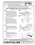
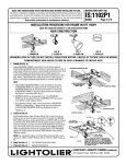
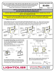
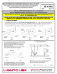
READ AND UNDERSTAND THESE INSTRUCTIONS BEFORE INSTALLING FIXTURE
INSTRUCTION SHEET NO.
This fixture is intended for installation in accordance with the National Electrical Code and local
regulations. To assure full compliance with local codes and regulations, check with your local electrical
inspector before installation. To prevent electrical shock, turn off electricity at fuse box before proceeding.
IS:1000IC
BO297
Retain these instructions for maintenance reference.
Page 1 of 1
INSTALLATION PROCEDURE FOR FRAME-IN KIT:
1000ICM, 1000AICM, 1100IC, 1100ICM,1100AICM, 1100DICM,1100DAICM
NOTE: I.C. Frame-in Kit may be used in direct contact with insulation.
ADJUSTABLE
MOUNTING BAR
1. FRAME-IN AND WIRE-IN
Line up bottom edge of ADJUSTABLE MOUNTING BAR with bottom of wood
joist. (FIG. A). Fasten MOUNTING FRAME to wood joist by nailing MOUNTING
BAR TAB or nail into joist. Wire to supply leads. White fixture lead to neutral
supply lead. Black fixture lead to hot (120V.) supply lead. Bare fixture wire to
supply ground. Use wirenuts (local hardware items.) Place all electrical connections in the J-Box. Attach J-BOX COVER onto J-Box. (Use built-in CABLE
CLAMP in J-Box or non-metallic sheathed cable Romex.)
NOTE: • Adjustable Mounting Bars can be installed either on long or short
side of Mounting Frame (except for 1000AICM, 1100AICM,
1100DICM, and 1100DAICM). Locking screws provided to lock frame
in a desired position.
•Mounting Bars can be extended to 24”. The Mounting Frame can be
mounted off center. Align SLOT of one Mounting Bar with hole of the
other Mounting Bar and drive screw into hole (not required for
1100DICM and 1100DAICM). Take pliers and bend tab on Mounting
Frame over towards extended Mounting Bar until Mounting Frame no
longer slides along Mounting Bars. (FIG.B) CENTERING SLOTS are
provided as guides to align adjacent frames.
•For 1131 and 1133 series sloped ceiling trims, Mounting Frame must
be mounted with J-BOX on the “uphill” side. Mounting Frame should
be parallel to the joist. (FIG. C)
•For suspended ceiling, make certain that bottom of Mounting Frame
is no longer than 1” above ceiling line, and notched area of
Adjustable Mounting Bars are positioned on top of T-Bar. (FIG.D)
MOUNTING FRAME
CENTERING SLOTS
FIG.A
SCREW
LINE UP BOTTOM
EDGE WITH BOTTOM
OF WOOD JOIST
TABS
MOUNTING FRAME
MOUNTING BAR
FIG.B
24”
J-BOX
WOOD JOIST
2. CLOSE-IN
Install plasterboard or other dry type ceiling. Hole in board can be cut either on
floor or after the board is nailed to the ceiling, using Mounting Frame opening
as cutting guide (make sure ROTO CLIPS are rotated out of hole area). Roto
Clips can only be rotated counterclockwise. This detail allows easy removal of
reflector trim by rotating TRIM counterclockwise and permits installing Reflector Trim tightly against the ceiling surface by rotating trim clockwise after
pushing Trim into ceiling.
NOTE: For 1000AICM, 1100AICM, and 1100DAICM apply a bead of
silicone caulking compound between the ceiling opening and edge of
fixture housing. For wet plaster ceiling, use plaster ring accessory No.1960
(order separately): No.1960 for 1000 series Frame-in kit, No. 1961 for 1100
series Frame-in Kit.
3. ATTACH SOCKET TO TRIM
4. PUSH-UP
}
SEE SEPARATE REFLECTOR
TRIM INSTRUCTION SHEETS
MOUNTING BAR
FIG.C
SOCKET CUP
11/2” MAX.
D1
ADJUSTABLE
MOUNTING BAR
D2
T-BAR
1” MAX.
Position notched areas of adjustable mounting bar on top of T-bar for
proper spacing to finished ceiling. Lock mounting bars by bending
tab underneath T-bar bead (FIG. D1), or use screw for round T-bar
bead to lock bars, (FIG. D2)
FIG.D
WARNING: USE ONLY LIGHTOLIER REFLECTOR TRIMS MARKED WITH I.C. LAMPING INFORMATION.
WARNING: USE ONLY WITH TRIMS DESIGNATED BY LIGHTOLIER USE OF OTHER MANUFACTURERS’ TRIMS
VOIDS THE UNDERWRITERS LABORATORIES LISTING AND COULD CONSTITUTE A FIRE HAZARD.
U.S. PATENT NOS. 4,313,514; 5,045,985
®
FALL RIVER, MASSACHUSETTS, 02720
MONTREAL, QUEBEC, CANADA