1
Lighting Systems
1BHFPG
LFK2
-JHIU51FS'PPUDN
/PNJOBM
4FDUJPO
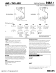
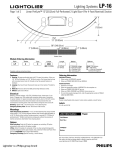
4.895” (12.43cm)
1
4.295"
(10.91cm)
2
3.400"
(8.64cm)
Half Scale
6
Ordering Information
Family
Lamps
LFK
1
1 = 1 lamp per
4’ (121.92cm)
Complete Ordering Instructions below.
Shielding
5
4
3
Voltage
Wattage
Length
Options
L
L = Louver
28 = 28w T5
1 = 120v
54 = 54w T5
2 = 277v
2D = 28w T5 Dimming
5D = 54w T5 Dimming
2E = 28w T5 Emergency Pack
5E = 54w T5 Emergency Pack
4 = 4’ (121.92cm)
8 = 8’ (243.84cm)
DS = Dual Switch
X4 = 4 Through Wires
X5 = 5 Through Wires
Features
Mounting
1. Extrusion: Extruded aluminum, painted white.
2. Housing: Multi-layered 5/8" (1.59cm) thick polycarbonate panels with patented
prism design. Clear outer layer and an opal non-glare inner layer. Light
transmission is 32% ASTM D1003 perpendicular to the panel. Reflectivity is
more than 40% perpendicular to the panel.
3. Endcap: Die cast aluminum, painted white.
4. Ballast Channel: Accepts linear fluorescent ballasts up to 1.2" (3.05cm) wide
by 1.2" (3.05cm) tall.
5. Lamp: T5 linear fluorescent, 28 or 54 watt. (by others).
Mounting locations are adjustable along the top of the extrusion. Cable suspension
(not shown) consists of 4 1/2" (11.43cm) diameter canopy finished white enamel,
1/16" (0.16cm) diameter stainless steel aircraft cable adjustable up to 36”
(91.44cm). Draw-tight connector to create hairline seam between joiner modules.
Modules allow 6” (15.24cm) of suspension position adjustment.
Electrical
Ballast: Electronic and meets A.N.S.I. starting, end of life protection, T.H.D., "A"
sound rating, and end-of-life specifications. Factory installed ballast disconnect
allows the ballast to be disconnected from and reconnected to incoming power
under load without turning the entire circuit off.
Wiring: 3 Conductor 18 gauge wire. Color-coded quick connectors allow ease of
connection for fixture modules.
Dimming: Advance Mark X. Use Advance compatible 2 wire control (no extra lead
is required in the luminaire).
Emergency Battery Pack: 54 Watt: 390-700 Lumens for 90 minutes,
28 Watt: 370-520 Lumens for 90 minutes.
Dual Switching: Order the DS option for separate row switching. DS option
comes complete with the 4th through wire option.
4 and 5 wire: Order X4 for EM Battery Pack. For non-standard dimming options
order X5 option for Osram or DALI 54 watt dimming, X4 option for Lutron HiLume
or ECO-10 54 Watt dimming.
Consult Factory for any additional wiring conditions.
Finish
Powder coated white baked enamel. Custom colors available, consult factory.
Ordering Instructions
Individual Fixtures:
1. Order number of MODULES required.
2. Order one POWER FEED CABLE END SET per MODULE.
Continuous Rows:
1. Determine run length.
2. Order the appropriate number of MODULES for the complete run.
3. Order one POWER FEED CABLE END SET per run.
4. Order one INTERMEDIATE CABLE SET per MODULE minus one per run.
5. For runs that exceed amperage limits, order the appropriate number of
CABLE/CORD SET.
Labels
UL , cUL and I.B.E.W. Patent Applied For.
Job Information
Type:
Job Name:
Cat. No.:
Lamp(s):
Notes:
"JSQPSU3PBE'BMM3JWFS."t
t'BY
We reserve the right to change details of design, materials and finish.
XXXMJHIUPMJFSDPN½1IJMJQT(SPVQt #
Lighting Systems
1BHFPG
LFK2
-JHIU51FS'PPUDN
/PNJOBM
4FDUJPO
Performance
COEFFICIENTS OF UTILIZATION
% EFFECTIVE CEILING CAVITY REFLECTANCE
CANDLEPOWER
ZONE
DEG.
180
175
165
155
145
135
125
115
105
95
90
85
75
65
55
45
35
25
15
5
0
REPORT NO.: ITL54308
LAMPS: 1-F54T5
LUMENS: 5000
EFFICIENCY: 73.5%
CAT NO.: LFK1L5414
0
22
45
67
90
183
186
155
178
334
475
236
182
170
155
148
157
196
286
412
762
871
913
952
928
912
183
186
152
184
392
452
211
199
192
187
180
184
196
304
412
763
949
961
975
933
912
80%
CANDELAS
183
183
184
180
170
156
135
100
60
16
0
11
57
113
183
349
513
667
798
896
912
183
184
184
162
153
160
186
237
66
38
28
40
104
263
322
466
618
748
841
905
912
183
184
162
166
200
350
342
141
115
90
80
90
150
234
495
657
733
832
909
920
912
ROOM CAVITY RATIO
CANDLEPOWER CURVE
70
82
74
68
62
57
52
48
45
42
39
36
0
1
2
3
4
5
6
7
8
9
10
50
82
71
62
55
49
43
39
35
32
29
27
30
82
68
57
49
43
37
33
29
26
24
22
70%
WALL REFLECTANCE
70 50 30
50
77 77 77
69
70 67 64
60
64 59 55
52
58 52 47
46
53 46 41
41
49 41 36
37
45 37 32
34
42 34 28
31
39 31 25
28
37 28 23
26
34 26 21
24
50%
30
69
58
49
42
37
33
29
26
23
21
19
10
69
56
46
39
34
29
25
23
20
18
16
20% FLOOR CAVITY REFLECTANCE
DISTRIBUTION
Zone
Lumens
0-90
2506
90-180
1170
0-180
3677
% Lamp %Luminaire
50.0
68.0
23.5
32.0
73.5
100.0
Fixture Lengths & Mounting
4' (121.92cm)
8' (243.48cm)
8' (243.48cm)
8’ 0-3/4" (245.75cm)
12’ 0-3/4" (367.67cm)
8' (243.48cm)
8' (243.48cm)
4' (121.92cm)
4’ 0-3/4"
(123.83cm)
16’ 0-3/4" (489.59cm)
8' (243.48cm)
Note: All suspension points have
6" (15.24cm) of adjustment within
each module. 12" (30.48cm) when
two modules are joined. Field
cutting of wire cover is required.
8' (243.48cm)
4' (121.92cm)
20’ 0-3/4" (611.51cm)
8' (243.48cm)
8' (243.48cm)
8' (243.48cm)
24’ 0-3/4" (733.43cm)
Mounting Accessories
Power Feed Cable End Set
Cable length is 36" (91.44cm)
Straight Cord: LFKEC36WH
4 Wire Cord: LFKEC36WHX4
5 Wire Cord: LFKEC36WHX5
Intermediate Cable Set
Cable length is 36" (91.44cm)
Single Cable: LFKC36
Intermediate
Cable/Cord Set
Cable length is 36" (91.44cm)
Straight Cord: LFKCC36
4 Wire Cord: LFKCC36X4
5 Wire Cord: LFKCC36X5
Ceiling Grid Kit (CGK)
Includes both standard
1" (2.54cm) Tee and Slot
Tee Clip.
Order one for every nonpowered suspension point.
Job Information
Ceiling Grid Kit—
Power (CGKP)
Includes the hardware
necessary to install a
power feed above a
suspended ceiling. J-box
not included. Order one for
every powered suspension
point.
Type:
"JSQPSU3PBE'BMM3JWFS."t
t'BY
We reserve the right to change details of design, materials and finish.
XXXMJHIUPMJFSDPN½1IJMJQT(SPVQt #