1
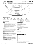
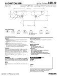
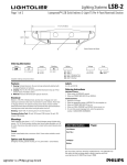
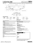
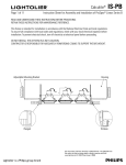
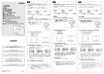
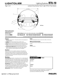
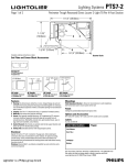
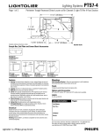
Lighting Systems
1BHFPG
LP-15
-JOFBS1FSG-ZUFÜDN
'VMM1FSGPSBUFE-JHIU51FS'PPU/PNJOBM
4FDUJPO
3”
(7.62cm)
Perf
13” (33.02cm)
98” (248.92cm)
2” (5.08cm)
2” (5.08cm)
2” (5.08cm)
Bottom View
Module Ordering Information
Style
Series
Type
LP
2
B
Lamps
Length
Options
Ballast
2T8
2T8 = 2-F32T8
4 = 4-Foot
8 = 8-Foot
Complete ordering instructions below.
U = Universal Voltage
E = Emergency Pack
D1 = Dimming 120v
D2 = Dimming 277v
Blank = No Options
DS = A-B Switch
X4 = 4 Wire for Dimming &
Switched Emergency
Features
Ordering Information
1. Housing: 18 gauge perforated steel with 51% open hole pattern. Holes are
1/8” (0.32cm) diameter on 5/32” (0.40cm) centers. Die-formed steel end cap
with concealed access holes for through wiring. No exposed fasteners or
hardware.
2. Lamping: Two T8 32 watt fluorescent lamps per 4-foot section. Provided by
others.
3. Reflector: Precision die-formed CRS painted high reflectance white.
4. Diffuser: Opal acrylic diffuser.
Individual Fixtures:
1. Order number of MODULES required.
2. Order one POWER FEED END SET per MODULE.
Electrical
Ballast is universal voltage, <10% THD, .88 ballast factor, instant start. 3 conductor, 18 gauge wire. Color-coded quick connectors allow ease of connection
for joiner modules. For special circuiting consult factory. Cord is 18/3 SJT. Factory
installed ballast disconnect allows the ballast to be disconnected from and
reconnected to incoming power under load without turning the entire circuit off.
Dimming: 120/277 VAC, 4 wire feed required.
Emergency Battery Pack: 32 watt: 450 lumens @ 90 minutes.
Continuous Rows:
1. Determine run length.
2. Order the appropriate number of MODULES for the complete run.
3. Order one POWER FEED END SET per run.
4. Order one CABLE ASSEMBLY per MODULE minus one per run.
5. For runs that exceed amperage limits, order the appropriate number of SINGLE
CABLE & CORD FEEDS.
Finish
Powder coated baked white enamel. Custom colors available, consult factory.
Labels
UL, cUL and I.B.E.W.
Mountings
Cable Suspension (not shown) - 4-1/2” (11.43cm) diameter flat canopy finished
white enamel, 1/16” (0.16cm) diameter stainless steel aircraft cable adjustable up
to 36” (91.44cm) without cutting. Overlap connector to provide 46” (116.84cm) of
perforated and 2” (5.08cm) solid sections contiguously without the presence of
hairline connections. (See Bottom View drawing above)
Job Information
Type:
Job Name:
Cat. No.:
Options
Dual Switching: Order the DS option for separate row switching. DS option
automatically ships with the X4 option included.
4 Wire: Order X4 modules for remainder of the run when using dimming and/or
switched emergency battery pack modules. Also, order the 4 Wire Cord Power Feed
End Sets (LP2EC36X4) when using 4 Wire Modules.
Emergency Circuiting: Special circuiting - consult factory.
Lamp(s):
Notes:
"JSQPSU3PBE'BMM3JWFS."t
t'BY
We reserve the right to change details of design, materials and finish.
XXXMJHIUPMJFSDPN½1IJMJQT(SPVQt #
Lighting Systems
1BHFPG
LP-15
-JOFBS1FSG-ZUFÜDN
'VMM1FSGPSBUFE-JHIU51FS'PPU/PNJOBM
4FDUJPO
Performance
ZONE
DEG.
REPORT NO: LRL 1199-5A
CAT NO: LP2C2T84U
LAMPS: 2 F32T8
LUMENS: 2900
EFFICIENCY: 80.7%
0
180 1107
175 1109
165 1072
155
996
145
875
135
713
125
573
115
392
105
208
95
41
90
0
85
8
75
29
65
59
55
129
45
177
35
237
25
282
15
313
5
331
0
330
CANDLEPOWER
22
45
CANDELAS
1107 1107
1108 1111
1079 1097
1015 1045
919
972
778
840
639
726
475
536
285
356
112
135
18
33
19
28
37
54
70
89
133
147
180
186
239
243
282
284
314
314
330
331
330
330
67
1107
1110
1107
1084
1032
914
790
591
433
156
48
40
70
105
165
198
250
288
316
328
330
COEFFICIENTS OF UTILIZATION
% EFFECTIVE CEILING CAVITY
REFLECTANCE
90
1107
1110
1105
1092
1049
926
762
610
448
161
55
45
75
111
165
202
253
289
315
330
330
80
ROOM CAVITY RATIO
CANDLEPOWER CURVE
70
50
WALL REFLECTANCE
70 50 30 70 50 30 50 30
0 80 80 80 71 71 71 53 53
1 73 70 67 64 62 59 46 45
2 67 61 57 59 54 50 41 38
3 61 54 49 54 48 43 36 33
4 56 48 42 49 42 37 32 29
5 51 42 36 45 38 32 29 25
6 47 38 32 41 34 28 26 22
7 43 34 28 38 30 25 23 20
8 40 31 25 35 27 22 21 17
9 37 28 22 33 25 20 19 16
10 34 25 20 30 22 18 17 14
20% FLOOR CAVITY REFLECTANCE
DISTRIBUTION
Lumens
Zone
0-90
859
90-180 3822
0-180
4681
% Lamp
14.8
65.9
80.7
10
53
43
36
31
26
22
19
17
15
13
11
% Luminaire
18.3
81.7
100.0
Fixture Lengths & Mounting Locations
96” (243.84cm)
48” (121.92cm)
4’
4’ 2” (127.00cm)
4-Foot 8-Foot
End Set
Module Module
4-Foot Run
1
1
8-Foot Run
1
1
12-Foot Run
1
1
1
16-Foot Run
2
1
20'-Foot Run
1
2
1
24'-Foot Run
3
1
8’
8’ 2” (248.92cm)
96” (243.84cm)
48” (121.92cm)
12’
12’ 2” (370.84cm)
96” (243.84cm)
16’
96” (243.84cm)
Cable/
Joiner
1
1
2
2
16’ 2” (492.76cm)
96” (243.84cm)
20’
96” (243.84cm)
48” (121.92cm)
20’ 2” (614.68cm)
96” (243.84cm)
24’
96” (243.84cm)
96” (243.84cm)
24’ 2” (736.60cm)
Mounting Accessories
Cable/Joiner Assembly
Standard Cable Length is 36” (91.44cm)
Single Cable: LP2C36
Single Cable & Cord: LP2CC36
Single Cable & 4 Wire Cord: LP2CC36X4
Power Feed End Set
Standard Cable Length is 36” (91.44cm)
Straight Cord: LP2EC36
4 Wire Cord*: LP2EC36X4
* use for dimming and/or
emergency battery packs
Ceiling Grid Kit
CGK
Includes both Standard 1” (2.54cm)
Tee Bar Clip & Slot Tee Clip
Job Information
Type:
"JSQPSU3PBE'BMM3JWFS."t
t'BY
We reserve the right to change details of design, materials and finish.
XXXMJHIUPMJFSDPN½1IJMJQT(SPVQt #