Transcript
READ AND UNDERSTAND THESE INSTRUCTIONS BEFORE INSTALLING FIXTURE
INSTRUCTION SHEET NO.
This fixture is intended for installation in accordance with the National Electrical Code and local regulations. To
assure full compliance with local codes and regulations, check with your local electrical inspector before
installation. To prevent electric shock, turn off electricity at fuse box before proceeding.
IS:CACP
Retain these instructions for maintenance reference.
Page 1 of 1
A0604
INSTALLATION PROCEDURE FOR: CEILING MOUNT CABLE PENDANT KIT CACP SERIES
USED WITH CEILING MOUNT CYLINDERS (ORDER SEPARATELY)
WARNING: USE ONLY FIXTURE PROVIDED BY LIGHTOLIER.
USE OF OTHER MANUFACTURES’ FIXTURES MAY VOID
THE UNDERWRITERS LABRATORIES LISTING AND COULD CONSTITUTE A FIRE HAZARD.
OCTAGON
OUTLET BOX
(BY OTHERS)
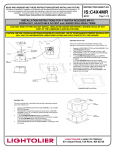
INSTALLATION OF CABLE PENDANT KIT ONTO
CEILING (Fig. 1) (NOTE: If custom length is required see below.)
1. Bring supply leads from OCTAGON OUTLET BOX and fixture leads
through the cutout of MOUNTING PLATE.
2. Thread OUTLET BOX SCREWS through slots in MOUNTING
PLATE to OUTLET BOX.
3. Make Connections. Bare Copper and/or green insulation wire(s)
must be connected to SUPPLY GROUND. Connect WHITE
LEAD to NEUTRAL (WHITE) SUPPLY LEAD. Connect BLACK
LEAD to HOT SUPPLY LEAD. Use wire nuts (local hardware items).
Push spliced leads into outlet box.
4. Place CANOPY through THREADED NIPPLE over MOUNTING
PLATE and push up against ceiling, then tighten LOCK NUT.
FIXTURE
LEADS
MOUNTING
PLATE
CUTOUT
THREADED
NIPPLE
OUTLET BOX
SCREWS
CANOPY
HANGER FITTING
LOCK NUT
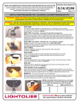
INSTRUCTIONS FOR SHORTENING CABLES and
POWER CORD (Fig. 1 & 2)
Shorten the cable and cord before the kit is installed to avoid excess
PLUNGER
cables in the internal wiring area. If it is necessary to install the kit
first, then follow the installation steps below.
1. Height Adjustment: To raise SUPPORT COVER, push CABLE up
into HANGER FITTING. To lower SUPPORT COVER, push up on
Plunger and allow SUPPORT COVER to drop to desired height.
Once SUPPORT COVER is set to the desired height, remove
LOCK NUT from CANOPY and lower onto top of SUPPORT COVER.
If necessary, cut excess CABLE from the back of canopy, leave
about 2” long or cap ends with wire nuts.
2. Reinstall CANOPY back to MOUNTING PLATE with LOCKNUT.
3. Push excess POWER CORD down, and have it loose above
SUPPORT COVER to ensure the power cord is not supporting the
support cover and cylinder; leave enough length for restripping the
cord. Cut excess at the end of POWER CORD and restrip the ends.
Tighten SET SCREW into CORD BUSHING to secure POWER
CORD. (Fig. 2 )
CABLE
POWER
CORD
LOCK
BUSHING
SUPPORT
COVER
THUMB NUT
FIG. 1
INSTALLATION OF CEILING MOUNT CYLINDER TO
CABLE PENDANT KIT (Fig. 1 & 2)
1. Make Connections. Bare Copper and/or green insulation wire(s)
must be connected to SUPPLY GROUND. Connect WHITE
BALLAST LEAD to NEUTRAL (WHITE) SUPPLY LEAD. Connect
BLACK BALLAST LEAD to HOT SUPPLY LEAD. Use wire nuts
(provided). Place spliced leads into SUPPORT COVER.
2. Remove (3) THUMB NUTS from SUPPORT COVER, and discard.
3. Align (3) holes in SUPPORT COVER with (3) tap holes in top of
CYLINDER (not shown), then tighten with (3) LOCK BUSHINGS.
CORD
BUSHING
SUPPORT
COVER
LOCK
BUSHING
FIG. 2
A
COMPANY
631 Airport Road, Fall River, MA 02720