1
READ AND UNDERSTAND THESE INSTRUCTIONS BEFORE INSTALLING FIXTURE
INSTRUCTION SHEET NO.
This fixture is intended for installation in accordance with the National Electrical Code and local regulations. To
assure full compliance with local codes and regulations, check with your local electrical inspector before
installation. To prevent electric shock, turn off electricity at fuse box before proceeding.
IS:C4CEX
Retain these instructions for maintenance reference.
A0604
Page 1 of 2
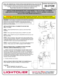
INSTALLATION PROCEDURE FOR: C4CEX (EXPO) SERIES H.I.D. SURFACE CYLINDER
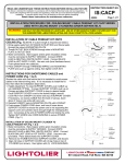
STEP 1: Screw OUTLET BOX SCREWS (not provided) to 4”
octagon outlet box, leaving about ¼” space for engaging the
MOUNTING PLATE.
STEP 2: Pass supply wires into large wire-way hole of MOUNTING
PLATE.
OUTLET BOX
SCREWS
STEP 3: Position key slots in MOUNTING PLATE onto the heads
MOUNTING PLATE
of OUTLET BOX SCREWS; shift housing into place and secure by
tightening the screws firmly.
BALLAST
SUPPORT
CAP NUTS
STEP 4: Make Connections. Bare Copper and/or green insulation
wire(s) must be connected to SUPPLY GROUND. Connect WHITE
BALLAST LEAD to NUETRAL (WHITE) SUPPLY LEAD. Connect
BLACK BALLAST LEAD to HOT SUPPLY LEAD. Use wire nuts
(local hardware items). Place wire nuts into outlet box.
INNER BALLAST
ASSEMBLY
STEP 5: Install BALLAST SUPPORT onto MOUNTING PLATE,
REFLECTOR
secure with threaded CAP NUTS (DO NOT OVER TORQUE),
RETAINING SPRING
STEP 6: Install lamp. (Use only T4.5 metal halide lamp with G8.5
base).
LAMP BARRIER
STEP 7: Install LAMP BARRIER into the INNER GLASS assembly
INNER GLASS
and secure with RETAINING SPRING.
STEP 8: Attach the INNER GLASS assembly to the REFLECTOR
by lining up the pins on the REFLECTOR and the slots on the INNER
GLASS assembly and turn clockwise until tight.
OUTER GLASS
STEP 9: Install OUTER GLASS by positioning over the INNER
BALLAST ASSEMBLY and secure with three set screws
STEP 10: Position REFLECTOR HOUSING onto center stud,
secure it with LOCK.
UPPER HOUSING
STEP 11: Slide the UPPER HOUSING over the OUTER GLASS
and attach to the INNER BALLAST ASSEMBLY. Secure by twisting
the housing clockwise until tight.
CAUTION: DO NOT ENERGIZE
THE LAMP UNTIL THE FIXTURE
IS COMPLETELY ASSEMBLED
AND INSTALLED.
A
COMPANY
631 Airport Road, Fall River, MA 02720
READ AND UNDERSTAND THESE INSTRUCTIONS BEFORE INSTALLING FIXTURE
INSTRUCTION SHEET NO.
This fixture is intended for installation in accordance with the National Electrical Code and local regulations. To
assure full compliance with local codes and regulations, check with your local electrical inspector before
installation. To prevent electric shock, turn off electricity at fuse box before proceeding.
IS:C4CEX
Retain these instructions for maintenance reference.
Page 2 of 2
A0604
INSTALLATION PROCEDURE FOR: EXPO ROD/TRIM KIT (CAT. NO. CAEXPT)
H.I.D. SURFACE CYLINDER
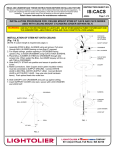
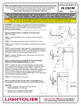
NOTE: EXPO Rod/Trim Kit can be installed without detaching outer
glass.
STEP 1: Install ROD into threaded hole in EXPO DECORATIVE
CYLINDER, repeat with the other two rods. Make sure rods are all
the way In.
EXPO
DECORATIVE CYLINDER
CAT. NO. C4CEX SERIES
STEP 2: Align bottom end of RODS with holes in GLASS DISC,
OUTER GLASS
position GLASS DISC onto the bottom lip of OUTER GLASS, then
secures with LOCK NUTS.
RODS
GLASS DISC
LOCK NUTS
COMPLETED
A
COMPANY
631 Airport Road, Fall River, MA 02720