Transcript
INSTRUCTION SHEET NO.
READ AND UNDERSTAND THESE INSTRUCTIONS BEFORE INSTALLING LUMINAIRE
This luminaire is intended for installation in accordance with the National Electrical Code and local regulations.
To assure full compliance with local codes and regulations, check with your local electrical inspector before
installation. To prevent electric shock, turn off electricity at fuse box before proceeding.
IS:406
Retain these instructions for maintenance reference.
B1004
Page 1 of 1
INSTRUCTION SHEET FOR 6.5” PENDALYTE™
Note: This instruction sheet covers several luminaire styles. Powerhead assembly, lamp type,
and reflector style may vary slightly from that shown, although installation is the same.
8.
9.
KNOT
CANOPY
BRACKET
BALLAST
OUTLET BOX
SCREWS
RELIEF
BUSHING
CORD
CANOPY
NEUTRAL
5.
6.
7.
120/277V
4.
GREEN
GREEN (OUTLET BOX PLATE GROUND)
GREEN
GREEN
WHITE
2.
3.
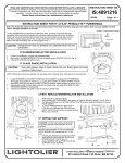
Remove CANOPY. Pull supply wires through hole in center of OUTLET BOX PLATE (Fig. 1) and
attach OUTLET BOX PLATE to outlet box using OUTLET BOX SCREWS (provided with outlet
box).
Pass CORD through hole in center of CANOPY.
Determine desired CORD length and attach RELIEF BUSHING to CORD with pliers. NOTE: Be
certain of CORD length before attaching RELIEF BUSHING as it is difficult to remove and
reposition.
Align HINGE on RELIEF BUSHING with HINGE MARK on CANOPY BRACKET (Fig. 2) and snap
into square hole in CANOPY BRACKET.
Tie KNOT in CORD above the CANOPY BRACKET.
To wire compact fluorescent unit see wire diagram below. Use wire nuts provided.
Using WIRE NUTS (local hardware item) make electrical connections: black BALLAST lead to hot
(black) supply lead; white BALLAST lead to neutral (white) supply lead. Green BALLAST lead is
ground wire and must be connected to grounding terminal or ground lead inside outlet box.
To wire incandescent unit: Using WIRE NUTS (local hardware item) connect black CORD wire to
hot (black) supply lead, connect white CORD wire to neutral (white) supply lead, green CORD wire
is ground wire and must be connected to grounding terminal or ground lead inside outlet box.
Attach CANOPY to CANOPY BRACKET with black CANOPY SCREWS.
BLACK
1.
OUTLET BOX PLATE
WIRE
NUTS
RE D
RED
BALLAST
RED/WHITE
RED
CORD
BLUE
BLUE
BLUE
BLUE/WHITE
Fig. 1
WIRE DIAGRAM
CAUTION: MAXIMUM WATTAGE AS MARKED
GLASS SHADE INSTALLATION (fig.3)
CORD
1.
RELIEF
BUSHING
HINGE
MARK
2.
3.
CANOPY SCREWS
Insert RETAINER CUP through top
of glass SHADE.
Place O-RING over RETAINER
CUP.
Align RETAINER CUP with
THREADED INSERTS in socket
plate.
CANOPY
BRACKET
ON LUMINAIRE MUST NOT BE EXCEEDED.
THREADED INSERTS
RETAINER CUP
GASKET STRIP
REFLECTOR
ADHESIVE BACKING
Fig. 2
8-32 SCREWS
THREADED INSERTS
Fig. 4
RETAINER CUP
ALUMINUM REFLECTOR INSTALLATION (Fig. 4)
O-RING
1.
2.
SHADE
3.
8-32 SCREWS
Peel ADHESIVE BACKING off of 3 GASKET STRIPS. Apply
GASKET STRIPS, equally spaced, to lip of RETAINER CUP.
Insert RETAINER CUP through top of REFLECTOR and align with
THREADED INSERTS in socket plate.
Secure with 8-32 screws.
Fig. 3
A
COMPANY
631 Airport Road, Fall River, MA 02720