Transcript
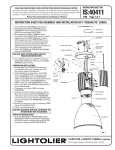
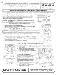
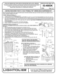
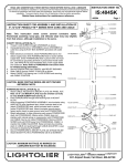
READ AND UNDERSTAND THESE INSTRUCTIONS BEFORE INSTALLING FIXTURE
This fixture is intended for installation in accordance with the National Electrical Code and local regulations. To
assure full compliance with local codes and regulations, check with your local electrical inspector before
installation. To prevent electric shock, turn off electricity at fuse box before proceeding.
Retain these instructions for maintenance reference.
INSTRUCTION SHEET NO.
IS:406BLS
A0105
Page 1 of 1
INSTRUCTIONS FOR 6.5” PENDALYTE™ SERIES TRACK MOUNT TO LYTESPAN ® TRACK SYSTEM SUSPENSION
KITS. FOR USE WITH LYTESPAN TRACK SYSTEMS ONLY.
CAUTION: MAXIMUM WATTAGE AS MARKED ON LUMINAIRE MUST NOT BE EXCEEDED.
#4 SCREWS
BODY
BRASS CONTACT
NICKEL CONTACT
POWER STEM INSTALLATION (fig. 1)
1. Slide STEM and BUSHING over POWERCORD. Align end of
POWERCORD with top of BUSHING tighten SET SCREW to secure
POWERCORD.
2. Twist stripped ends of POWERCORD wires an attach using CONTACT
SCREWS: attach hot (black POWERCORD lead to long BRASS
CONTACT, attach neutral (white) POWERCORD lead to short NICKEL
CONTACT, attach POWERCORD ground lead (green) to BODY with
green CONTACT SCREW.
3. Slide STEM up over contacts and secure to BODY using #4 SCREWS.
CONTACT
SCREWS
TRACK
STEM LEVER
BEAD
SET SCREW
BUSHING
Fig. 2
NOTE: Not for use with ProSpec track.
STEM
WARNING: TO PREVENT ELECTRIC
SHOCK, TURN OFF POWER TO TRACK.
POWERCORD
Fig. 1
INSTALLATION INTO TRACK (fig. 2)
1. Turn off power to TRACK.
2. Insert POWER STEM into track. The STEM LEVER must be on the
same side as the track bead. See fig. 2.
3. Rotate suspension stem 90° clockwise using STEM LEVER. STEM
LEVER should be parallel to TRACK.
4. To remove: rotate SUSPENSION STEM 90° counterclockwise using
STEM LEVER.
A
COMPANY
631 Airport Road, Fall River, MA 02720