1
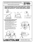
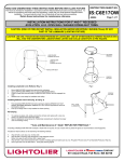
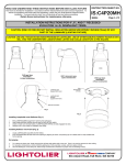
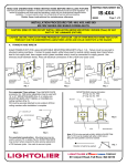
READ AND UNDERSTAND THESE INSTRUCTIONS BEFORE INSTALLING FIXTURE
INSTRUCTION SHEET NO.
This fixture is intended for installation in accordance with the National Electrical Code and local regulations. To
assure full compliance with local codes and regulations, check with your local electrical inspector before
installation. To prevent electric shock, turn off electricity at fuse box before proceeding.
IS:C12
Retain these instructions for maintenance reference.
Page 1 of 2
A1204
INSTALLATION PROCEDURE FOR: 12” DIA. H.I.D. C12 SERIES REFLECTOR TRIM TO
C12 SERIES FRAME-IN KIT AND C12CS/C12CW CYLINDER (ORDER SEPARATELY)
WARNING: USE ONLY REFLECTOR TRIMS PROVIDED BY LIGHTOLIER.
USE OF OTHER MANUFACTURES’ REFLECTOR
TRIMS MAY VOID THE UNDERWRITERS LABORATORIES LISTING AND COULD CONSTITUTE A FIRE HAZARD.
IF A NON-IC TYPE RECESSED FRAME-IN KIT IS USED, DO NOT INSTALL INSULATION ABOVE NOR WITHIN
3 INCHES (76mm) OF ANY PART OF THE LUMINAIRE (LIGHTING FIXTURE)
INSTRUCTIONS FOR INSTALLING C12E28V SERIES DOWNLIGHT
REFLECTOR TRIM
1. Attach SOCKET CUP to REFLECTOR ASSEMBLY by aligning (3) SCREWS
with key slots in REFLECTOR NECK, then tighten screws. (Fig. 1)
2. Position REFLECTOR ASSEMBLY into MOUNTING RING of Frame-In
Kit or Cylinder, align (4) FLATS in REFLECTOR ASSEMBLY with (4)
CONE RETAINING SPRINGS, and align REFLECTOR SPRINGS with
UPPER SLOTS in MOUNTING RING (Fig. 1 & 2). Then raise REFLECTOR
ASSEMBLY, to snap in place. (FIG. 1)
3. Before lamping, make sure power is disconnected to fixture.
Install lamp into lampholder.
4. Install COVER GLASS (required for enclosed lamp rated
fixture), line-up the edge of COVER GLASS with one spring
opposite notch on REFLECTOR ASSEMBLY and gently
push glass outward, then lift glass upward into position.
Rotate COVER GLASS so that NOTCH in COVER GLASS
is away from NOTCH in REFLECTOR ASSEMBLY. (Fig. 1 & 3)
5: Hook SAFETY BEAD CHAIN onto BEAD CHAIN COUPLER.
Position CONE so that bead chain is about horizontal, then push
CONE up into MOUNTING RING, then turn CONE clockwise
slightly for tight fit onto ceiling. CONE RETAINING SPRINGS will
hold cone in place. (Fig. 1 & 4)
FIG. 1
TO RELAMP
Disconnect power to fixture, then reverse installation
instructions above.
TO INSPECT AND REPLACE BALLAST
Disconnect power to fixture. Remove Cone. Detach REFLECTOR
ASSEMBLY by disengage REFLECTOR SPRINGS, move it to side
of fixture in the plenum, or in cylinder, remove from cylinder. See
IS:C4-C12 (Frame-In Kit), and IS:C12CS (Cylinder), for ballast
replacement. After service reverse Installation steps.
FIG. 2
FIG. 3
Care and Maintenance of REFLECTOR TRIM finish
If handling of REFLECTOR TRIM with anodized finish is required, the use
of clean white or plastic film gloves is recommended to avoid fingerprints.
Anodized surfaces can be cleaned by the following methods:
1. Wipe off with a soft, clean, dry, lint-free cloth.
2. Wipe off with a soft clean cloth dampened in mild detergent solution.
3. Rinse, then wipe dry with lint-free cloth or paper towel.
4. Wipe off with a clean cloth dampened with a solution of wetting agent
and water (such as 2 oz. Per gallon “Pluronic L62-LF” by Wyandotte
Products). Wipe dry.
5. Use a liquid wax such as Glass Wax®. Avoid gritty cleaning agents.
FIG. 4
a Genlyte company
631 Airport Road, Fall River, MA 02720
READ AND UNDERSTAND THESE INSTRUCTIONS BEFORE INSTALLING FIXTURE
INSTRUCTION SHEET NO.
This fixture is intended for installation in accordance with the National Electrical Code and local regulations. To
assure full compliance with local codes and regulations, check with your local electrical inspector before
installation. To prevent electric shock, turn off electricity at fuse box before proceeding.
IS:C12
Retain these instructions for maintenance reference.
A1204
Page 2 of 2
INSTALLATION PROCEDURE FOR: 12” DIA. H.I.D. C12 SERIES REFLECTOR TRIM TO
C12 SERIES FRAME-IN KIT AND C12CS/C12CW CYLINDER (ORDER SEPARATELY)
WARNING: USE ONLY REFLECTOR TRIMS PROVIDED BY LIGHTOLIER.
USE OF OTHER MANUFACTURES’ REFLECTOR
TRIMS MAY VOID THE UNDERWRITERS LABORATORIES LISTING AND COULD CONSTITUTE A FIRE HAZARD.
IF A NON-IC TYPE RECESSED FRAME-IN KIT IS USED, DO NOT INSTALL INSULATION ABOVE NOR WITHIN
3 INCHES (76mm) OF ANY PART OF THE LUMINAIRE (LIGHTING FIXTURE)
INSTRUCTIONS FOR INSTALLING C12E28FL AND C12E28PL
SERIES LENSLITE DOWNLIGHT REFLECTOR TRIM
INSTALLING SOCKET CUP TO REFLECTOR
1: Attach SOCKET CUP to REFLECTOR ASSEMBLY by aligning (3)
SCREWS with key slots in REFLECTOR NECK, then tighten screws.
(Fig. 1)
2: Raise REFLECTOR ASSEMBLY/SOCKET CUP into MOUNTING RING
of Frame-In Kit or Cylinder, align REFLECTOR SPRINGS with upper
slots in MOUNTING RING until springs snap in place. (Fig. 1)
3: Before lamping, make sure power is disconnected to fixture.
Install lamp into lampholder, (Fig. 1)
4. After REFLECTOR ASSEMBLY is installed, attach LENS BAFFLE by
squeezing TORSIONTITE SPRINGS together and insert through
SLOTS in REFLECTOR, then push up. (Fig.1)
5. For tamper proof installation, remove SET SCREW from outside of
LENS BAFFLE and re-install it with the allen wrench socket head facing
inside of LENS BAFFLE. Turn SET SCREW until socket head is about
1/8” inside baffle. Do not over turn. (Fig. 2) If SET SCREW was
properly installed, LENS BAFFLE should not pull down.
TO RELAMP
Disconnect power to fixture. Back out SET SCREW if used for tamper
proof installation. Lift lens up and grip top edge of baffle then pull down.
TO INSPECT AND REPLACE BALLAST
FIG. 1
Disconnect power to fixture. Back out SET SCREW if used for tamper
proof installation. Lift lens up and grip top edge of baffle then pull down and
detaching TORSIONTITE SPRINGS. Detach REFLECTOR ASSEMBLY
by disengage REFLECTOR SPRINGS, move it to side of fixture in the
plenum, or in cylinder, remove from cylinder. See IS:C4-C12 (Frame-In Kit)
and IS:C12CS (Cylinder) for ballast replacement. After service, reverse
Installation steps.
Care and Maintenance of REFLECTOR TRIM finish
If handling of REFLECTOR TRIM with anodized finish is required, the use
of clean white or plastic film gloves is recommended to avoid fingerprints.
Anodized surfaces can be cleaned by the following methods:
1. Wipe off with a soft, clean, dry, lint-free cloth.
2. Wipe off with a soft clean cloth dampened in mild detergent
3. solution. Rinse, then wipe dry with lint-free cloth or paper towel.
4. Wipe off with a clean cloth dampened with a solution of wetting agent
and water (such as 2 oz. Per gallon “Pluronic L62-LF” by Wyandotte
Products). Wipe dry.
5. Use a liquid wax such as Glass Wax®. Avoid gritty cleaning agents.
FIG.2
a Genlyte company
631 Airport Road, Fall River, MA 02720