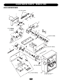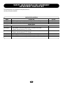
1
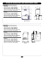
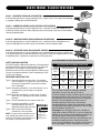
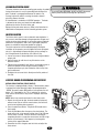
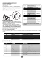
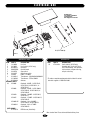
CO
NT
RO
LL
ER
GL
BO
AR
D
MODEL SL585
HEAVY DUTY SLIDE GATE OPERATOR
MODEL SL595
2 YEAR WARRANTY
Serial # ________________________
(located on electrical box cover)
Installation Date __________________
HEAVY DUTY, HARSH ENVIRONMENT
SLIDE GATE OPERATOR
MODELS SL585 AND SL595 ARE FOR VEHICULAR
PASSAGE GATES ONLY AND ARE NOT INTENDED FOR
PEDESTRIAN PASSAGE GATE USE
TABLE OF CONTENTS
OPERATOR SPECIFICATIONS
IMPORTANT NOTES
Carton Inventory . . . . . . . . . . . . . . . . . . . . . . . . . . . . . . . . . . . . .2
Operator Dimensions and Horsepower Chart . . . . . . . . . . . . . . .3
UL325 Model Classifications . . . . . . . . . . . . . . . . . . . . . . . . . . . .4
• BEFORE attempting to install, operate or maintain the operator,
you MUST read and fully understand this manual and follow all
safety instructions.
• DO NOT attempt repair or service of your commercial door and
gate operator unless you are an Authorized Service Technician.
OPERATOR WARNINGS
Safety Installation Information . . . . . . . . . . . . . . . . . . . . . . . . . .5
Suggested Entrapment Protection Device Locations . . . . . . . . . .6
Safety Precautions for Open Roller Gates . . . . . . . . . . . . . . . . . .7
Warning Sign Placement . . . . . . . . . . . . . . . . . . . . . . . . . . . . . . .7
WARNING
WIRING
Mechanical
Power Wiring Installation . . . . . . . . . . . . . . . . . . . . . . . . . . . . . .8
CAUTION
WARNING
WARNING
Electrical
WARNING
CAUTION
INSTALLATION
WARNING
Pad Mounting (SL585 & SL595) . . . . . . . . . . . . . . . . . . . . . . . . .9
Post Mounting (SL585 & SL595) . . . . . . . . . . . . . . . . . . . . . . .10
Install Gate Bracket and Drive Chain . . . . . . . . . . . . . . . . . . . . .11
On/Off Switch Power Wiring . . . . . . . . . . . . . . . . . . . . . . . . . . .12
Manual Disconnect . . . . . . . . . . . . . . . . . . . . . . . . . . . . . . . . . .12
CAUTION
ADJUSTMENT
Limit Switch Adjustment . . . . . . . . . . . . . . . . . . . . . . . . . . . . . .13
RPM Sensor Adjustment (Hall Effect) . . . . . . . . . . . . . . . . . . . .13
Gate System Test Procedures . . . . . . . . . . . . . . . . . . . . . . . . . .13
Vent Plug . . . . . . . . . . . . . . . . . . . . . . . . . . . . . . . . . . . . . . . . . .14
UL325 Entrapment Protection . . . . . . . . . . . . . . . . . . . . . . .14-15
Control Board Illustration . . . . . . . . . . . . . . . . . . . . . . . . . . . . .15
Program Settings . . . . . . . . . . . . . . . . . . . . . . . . . . . . . . . . . . .16
Control Connection Diagrams . . . . . . . . . . . . . . . . . . . . . . . . . .17
Accessory Wiring . . . . . . . . . . . . . . . . . . . . . . . . . . . . . . . . .18-19
Sequenced Access Management System . . . . . . . . . . . . . . . . .20
When you see these Safety Symbols and Signal Words on the
following pages, they will alert you to the possibility of SERIOUS
INJURY or DEATH if you do not comply with the warnings that
accompany them. The hazard may come from something
mechanical or from electric shock. Read the warnings carefully.
When you see this Signal Word on the following pages, it will
alert you to the possibility of damage to your gate and/or the gate
operator if you do not comply with the cautionary statements that
accompany it. Read them carefully.
OPERATION AND MAINTENANCE
Operator Maintenance . . . . . . . . . . . . . . . . . . . . . . . . . . . . . . . .21
Friction Clutch . . . . . . . . . . . . . . . . . . . . . . . . . . . . . . . . . . . . . .22
Solenoid Actuated Brake . . . . . . . . . . . . . . . . . . . . . . . . . . . . . .22
Control Board Programming and Features . . . . . . . . . . . . . .22-23
Troubleshooting . . . . . . . . . . . . . . . . . . . . . . . . . . . . . . . . . .24-25
Single Phase Schematic . . . . . . . . . . . . . . . . . . . . . . . . . . . . . .26
Single Phase Wiring Diagram . . . . . . . . . . . . . . . . . . . . . . . . . .27
Three Phase Schematic . . . . . . . . . . . . . . . . . . . . . . . . . . . . . . .28
Three Phase Wiring Diagram . . . . . . . . . . . . . . . . . . . . . . . . . . .29
CARTON INVENTORY
Before beginning your installation check that all components
were provided and received undamaged. Refer to list below
for factory provided parts.
HARDWARE KIT
SL585/SL595 (K77-34846)
REPAIR PARTS
Notes . . . . . . . . . . . . . . . . . . . . . . . . . . . . . . . . . . . . . . . . . . . . .30
Electrical Boxes . . . . . . . . . . . . . . . . . . . . . . . . . . . . . . . . . . . . .31
Repair Parts - Model SL585 . . . . . . . . . . . . . . . . . . . . . . . . . . .32
Illustrated Parts - Model SL585 . . . . . . . . . . . . . . . . . . . . . . . . .33
Repair Parts - Model SL595 . . . . . . . . . . . . . . . . . . . . . . . . . . .34
Illustrated Parts - Model SL595 . . . . . . . . . . . . . . . . . . . . . . . . .35
Safety Accessories for Secondary Entrapment Protection . . . .36
Notes . . . . . . . . . . . . . . . . . . . . . . . . . . . . . . . . . . . . . . . . . . . . .37
Warranty . . . . . . . . . . . . . . . . . . . . . . . . . . . . . . . . . . . . . . . . . .38
Service Information . . . . . . . . . . . . . . . . . . . . . . . . . . . . . . . . . .39
Description
Safety Gate Brochure
Gate Bracket
Take-Up Bolt
Nickel Plated Chain #50
U-Bolt 2" 5/16-18
U-Bolt 3" 3/8-16
Square Head Set Screw 7/16-14
Hex Nut 1/2-13
Flange Nut 5/16"-18
Flange Nut 3/8"-16
Flat Washer 3/8"
Flat Washer 1/2"
Lock Washer 1/2"
2
Qty.
1
2
2
1
4
4
4
4
8
8
8
4
4
O P E R AT O R D I M E N S I O N S A N D H O R S E P O W E R C H A R T
MODEL SL585
• 1/2 HP Motor
Maximum Gate Speed – 11"/sec. (27.9 cm/sec.)
Maximum Gate Weight – 1000 lbs. (453.6 kg)
Maximum Cantilever Gate Width – 25 ft. (7.6 m)
Maximum Overhead Roller Gate Width – 45 ft. (13.7 m)
Maximum V-Track Gate Width – 35 ft. (10.7 m)
28.9"
(73.4 cm)
27.5"
(69.9 cm)
• 1 HP Motor
Maximum Gate Speed – 11"/sec. (27.9 cm/sec.)
Maximum Gate Weight – 1600 lbs. (725.8 kg)
Maximum Cantilever Gate Width – 35 ft. (10.7 m)
Maximum Overhead Roller Gate Width – 70 ft. (21.3 m)
Maximum V-Track Gate Width – 50 ft. (15.2 m)
17.2"
(43.7 cm)
37.7"
(95.8 cm)
14.1"
(35.8 cm)
12.9"
(32.8 cm)
14.9"
(37.9 cm)
Opposite Gate Side
MODEL SL595
• 1/2 HP Motor
Maximum Gate Speed – 12"/sec. (30.5 cm/sec)
Maximum Gate Weight – 1100 lbs. (499 kg)
Maximum Cantilever Gate Width – 25 ft. (7.6 m)
Maximum Overhead Roller Gate Width – 45 ft. (13.7 m)
Maximum V-Track Gate Width – 35 ft. (10.7 m)
16.5"
(41.9 cm)
13.5"
(34.3 cm)
24"
(61 cm)
• 1 HP Motor
Maximum Gate Speed – 12"/sec. (30.5 cm/sec)
Maximum Gate Weight – 1700 lbs. (771.1 kg)
Maximum Cantilever Gate Width – 35 ft. (10.7 m)
Maximum Overhead Roller Gate Width – 70 ft. (21.3 m)
Maximum V-Track Gate Width – 50 ft. (15.2 m)
30"
(76.2 cm)
• 2 HP Motor
Maximum Gate Speed – 12"/sec. (30.5 cm/sec)
Maximum Gate Weight – 2500 lbs. (1134 kg)
Maximum Cantilever Gate Width – 45 ft. (13.7 m)
Maximum Overhead Roller Gate Width – 90 ft. (27.4 m)
Maximum V-Track Gate Width – 60 ft. (18.3 m)
12" Min.
(30.5 cm)
Gate Side
3
22.5"
(57.2 cm)
Allow
For
Door
Opening
3" (7.6 cm) Dia. Pipe
(Not Provided)
U L 3 2 5 M O D E L C L A S S I F I C AT I O N S
CLASS I – RESIDENTIAL VEHICULAR GATE OPERATOR
A vehicular gate operator (or system) intended for use in a home of one-to four single family dwellings,
or a garage or parking area associated therewith.
CLASS II – COMMERCIAL/GENERAL ACCESS VEHICULAR GATE OPERATOR
A vehicular gate operator (or system) intended for use in a commercial location or building such as a
multi-family housing unit (five or more single family units) hotel, garage, retail store or other building
servicing the general public.
CLASS III – INDUSTRIAL/LIMITED ACCESS VEHICULAR GATE OPERATOR
A vehicular gate operator (or system) intended for use in a industrial location or building such as a
factory or loading dock area or other location not intended to service the general public.
CLASS IV – RESTRICTED ACCESS VEHICULAR GATE OPERATOR
A vehicular gate operator (or system) intended for use in a guarded industrial location or building such
as an airport security area or other restricted access locations not servicing the general public, in which
unauthorized access is prevented via supervision by security personnel.
UL325 ENTRAPMENT PROTECTION REQUIREMENTS
SAFETY ACCESSORY SELECTION
All UL325 compliant LiftMaster gate operators will accept external
entrapment protection devices to protect people from motorized
gate systems. UL325 requires that the type of entrapment
protection correctly matches each gate application. Below are the
six types of entrapment protection systems recognized by UL325
for use on this operator.
GATE OPERATOR ENTRAPMENT PROTECTION
UL325
Installation
Class
ENTRAPMENT PROTECTION TYPES
Type A: Inherent obstruction sensing system, self-contained
within the operator. This system must sense and initiate
the reverse of the gate within two seconds of contact
with a solid object.
Type B1: Connections provided for a non-contact device, such as
a photoelectric eye can be used as a secondary
protection.
Type B2: Connections provided for a contact sensor. A contact
device such as a gate edge can be used for secondary
protection.
Type C: Inherent adjustable clutch or pressure relief valve.
Type D: Connections provided for a control
requiring continuous pressure to
operate the operator open and close.
Type E: Built-in audio alarm. Examples
include sirens, horns or buzzers.
Moving Gate Can Cause
Injury or Death
NOTE: UL requires that all installations must
KEEP CLEAR! Gate may move at any
time without prior warning.
have warning signs placed in plain view on
Do not let children operate the gate or
play in the gate area.
both sides of the gate to warn pedestrians of This entrance is for vehicles only.
Pedestrians must use separate entrance
the dangers of motorized gate systems.
Slide Gate Operator
Swing & Gate Barrier
(Arm) Operator
Primary
Type
Secondary
Type
Primary
Type
Secondary
Type
Class
I & II
A
B1, B2
or D
A or C
A, B1, B2,
or C
Class III
A, B1 or
B2
A, B1, B2,
D or E
A, B1, B2
or C
A, B1, B2,
C, D or E
Class IV
A, B1, B2
or D
A, B1, B2,
D or E
A, B1, B2,
C or D
A, B1, B2,
C, D or E
The chart above illustrates the entrapment protection
requirements for each of the four UL325 classes.
In order to complete a proper installation you must satisfy the
entrapment protection chart shown above. That means that
the installation must have one primary means of entrapment
protection and one independent secondary means of
entrapment protection. Both primary and secondary
entrapment protection methods must be designed, arranged
or configured to protect against entrapments in both the open
and close directions of gate travel.
For Example: For a slide gate system that is installed on a
single-family residence (UL325 Class I) you must provide the
following: As your primary type of entrapment protection you
must provide Type A inherent (built into the operator)
entrapment sensing and at least one of the following as your
secondary entrapment protection: Type B1- Non-contact
sensors such as photoelectric eyes, Type B2- Contact sensors
such as gate edges or Type D- Constant pressure control.
4
S A F ET Y I N S TA L L AT I O N I N F O R M AT I O N
1. Vehicular gate systems provide convenience and security. Gate systems are comprised of many component parts. The gate
operator is only one component. Each gate system is specifically designed for an individual application.
2. Gate operating system designers, installers and users must take into account the possible hazards associated with each individual
application. Improperly designed, installed or maintained systems can create risks for the user as well as the bystander. Gate
systems design and installation must reduce public exposure to potential hazards.
3. A gate operator can create high levels of force in its function as a component part of a gate system. Therefore, safety features
must be incorporated into every design. Specific safety features include:
• Gate Edges
• Guards for Exposed Rollers
• Photoelectric Sensors
• Screen Mesh
• Vertical Posts
• Instructional and Precautionary Signage
4. Install the gate operator only when:
a. The operator is appropriate for the construction and the usage class of the gate.
b. All openings of a horizontal swing gate are guarded or screened from the bottom of the gate to a minimum of 4' (1.2 m) above
the ground to prevent a 2-1/4" (57.15 mm) diameter sphere from passing through the openings anywhere in the gate, and in
that portion of the adjacent fence that the gate covers in the open position.
c. All exposed pinch points are eliminated or guarded, and guarding is supplied for exposed rollers.
5. The operator is intended for installation only on gates used for vehicles. Pedestrians must be supplied with a separate access
opening.
6. The gate must be installed in a location so that enough clearance is supplied between the gate and adjacent structures when
opening and closing to reduce the risk of entrapment. Swinging gates shall not open into public access areas.
7. The gate must be properly installed and work freely in both directions prior to the installation of the gate operator.
8. Controls must be far enough from the gate so that the user is prevented from coming in contact with the gate while operating the
controls.
9. Controls intended to be used to reset an operator after 2 sequential activations of the entrapment protection device or devices
must be located in the line of sight of the gate, or easily accessible controls shall have a security feature to prevent unauthorized
use.
10. All warning signs must be installed where visible, on each side of the gate.
11. For a gate operator utilizing a non-contact sensor:
a. See instructions on the placement of non-contact sensor for each type of application.
b. Care shall be exercised to reduce the risk of nuisance tripping, such as when a vehicle trips the sensor while the gate is still
moving.
c. One or more non-contact sensors shall be located where the risk of entrapment or obstruction exists, such as the perimeter
reachable by a moving gate or barrier.
12. For a gate operator utilizing a contact sensor such as an edge sensor:
a. A hard wired contact sensor shall be located and its wiring arranged so the communication between the sensor and the gate
operator is not subject to mechanical damage.
b. A wireless contact sensor such as the one that transmits radio frequency (RF) signals to the gate operator for entrapment
protection functions shall be located where the transmission of the signals are not obstructed or impeded by building
structures, natural landscaping or similar obstruction. A wireless contact sensor shall function under the intended end-use
conditions.
c. One or more contact sensors shall be located at the leading edge, trailing edge and post mounted both inside and outside of a
vehicular horizontal slide gate.
d. One or more contact sensors shall be located at the bottom edge of a vehicular vertical lift gate.
e. One or more contact sensors shall be located on the inside and outside leading edge of a swing gate. Additionally, if the bottom
edge of a swing gate is greater than 6" (152 mm) above the ground at any point in its arc of travel, one or more contact sensors
shall be located on the bottom edge.
5
S U G G E S T E D E N T R A P M E N T P R O T E C T I O N D E V I C E LO C AT I O N S
GATE SYSTEM (MASTER/SECOND SLIDE GATE)
Open
Edge
Gate 1
Photo Eyes for
Open Cycle
Close
Edge
Run Twisted Wire
from Loop
to Operator
STREET
Seal Loops
Interrupt
(Safety)
Loop
Gate 2
1-1/2" (37 mm)
4' (1.2 m)
Typical
Open
Edge
4' (1.2 m)
Typical
Loop Wire Layer
Interrupt
(Safety)
Loop
1/4" (6 mm) or Larger
Depending on Loop
Wire Size
COMPLEX
OR
PARKING LOT
6' (1.8 m)
12'
(3.7 m)
4' (1.2 m)
Typical
Photo Eyes for
Close Cycle
Photo Eyes for
Open Cycle
GATE SYSTEM (COMMERCIAL SLIDE GATE)
Telephone
Entry
System
Open
Edge
Close
Edge
STREET
Run twisted wire
from Loop
to Operator*
4'
8'
Interrupt
(Safety)
Loop
Photo eye for
close cycle
Photo eye for
open cycle
Seal Loops*
1-1/2"
4'
Typical
4'
Typical
4'
Typical
Interrupt
(Safety)
Loop
COMPLEX
OR
PARKING LOT
6
Loop wire*
layer
1/4" or larger for Loop
wire width depending
on Loop wire size
SAFETY PRECAUTIONS FOR OPEN ROLLER GATES
Gate Edge on
Rear of Gate for
Open Direction
WARNING
• Injuries occur when people get their hands or feet caught
between the top or bottom of the gate and the gate roller.
These potential pinch-points should be guarded against at all
times. Enclosed style gate tracks are available for refitting of
these rollers from many fence suppliers. Also, roller guards
are available for installing over the rollers.
• UL325 requires that, when used, contact sensors shall be
located at the leading edge, trailing edge, and be post
mounted both inside and outside of a vehicular horizontal
slide gate. Non-contact sensors such as photo eyes must
protect during both open and close gate cycles.
• Injuries occur when people put their hands and arms
through openings in the grill while the gate is operating.
They cannot retract their arm and it gets caught between the
moving gate grill and the stationary fence post or fence. This
potential hazard can be averted by placing a 4' (1.2 m)
screen mesh on the gate to prevent access through openings
anywhere the gate may travel. See Safety Brochure for
details. To prevent entrapment injuries, mount controls at
least 6' (1.8 m) from the gate or any moving parts of the
gate.
CAUTION
Photo Beam
for Open
Direction
Gate Edge on Fence
Post for Open Direction
Gate Edge On
Leading Edge of Gate
For Close Direction
WARNING
Unit
Additional Post Mounted Gate
Edge for Close Direction
WARNING
Photo Beam for
Close Direction
Additional Post Mounted Gate
Edge for Open Direction
Pinch-Point
Hazard
Always Test Gate Edges And
Photo Beams Anytime They Are
Adjusted Or Serviced
Pinch-Point
Hazard
Gate Edge
For Open Direction
Gate Edge
For Close
Direction
Gate Edge
Vertical Post Placed On Both
Sides of the Exposed
Rollers Can Prevent Hands
From Reaching These
Pinch-points
Gate Edge for
Close Direction
DO NOT MOUNT ACCESSORIES THAT ARE
ACCESSIBLE THROUGH GATE!
WARNING SIGN PLACEMENT
WARNING
WARNING
To prevent SERIOUS INJURY or DEATH from a moving gate:
• Install Warning signs on EACH side of gate in PLAIN VIEW.
• Permanently secure each Warning sign in a suitable
manner using fastening holes.
CAUTION
WARNING
NOT FOR USE AS PEDESTRIAN PASSAGE! This operator is
intended for vehicular use only. To prevent INJURY to
pedestrians, a separate pedestrian access should be supplied,
visible from the gate. Locate the pedestrian access where there is
not a chance of INJURY at any point during full movement of the
gate.
Moving Gate Can Cause
Injury or Death
KEEP CLEAR! Gate may move at any
time without prior warning.
Do not let children operate the gate or
play in the gate area.
This entrance is for vehicles only.
Pedestrians must use separate entrance
7
NING
W
IRING
WARNING
ION
WARNING
To reduce the risk of SEVERE INJURY or DEATH:
• ANY maintenance to the operator or in the area near the
operator MUST not be performed until disconnecting the
electrical power and locking-out the power via the operator
power switch. Upon completion of maintenance the area
MUST be cleared and secured, at that time the unit may be
returned to service.
• Disconnecting power at the fuse box BEFORE proceeding.
Operator MUST be properly grounded and connected in
accordance with local electrical codes. NOTE: The operator
should be on a separate fused line of adequate capacity.
• ALL electrical connections MUST be made by a qualified
individual.
• DO NOT install any wiring or attempt to run the operator
without consulting the wiring diagram. We recommend that
you Install an optional reversing edge BEFORE proceeding with
the control station installation.
• ALL power wiring should be on a dedicated circuit and well
protected. The location of the power disconnect should be
visible and clearly labeled.
• ALL power and control wiring MUST be run in separate
conduit.
• BEFORE installing power wiring or control stations be sure to
follow all specifications and warnings described below. Failure
to do so may result in SEVERE INJURY to persons and/or
damage to operator.
POWER WIRING INSTALLATION
Wiring Specifications (STRANDED COPPER WIRE)
On a Dual Gate System, each unit must be installed on ITS OWN separate circuits
WIRE GAUGE 6
• 1/2 HP Motor -----• 1 HP Motor---------• 2 HP Motor----------
SINGLE PHASE
115 Vac
230 Vac
230 Vac
THREE PHASE
460 Vac
575 Vac
425 ft. (129.5 m) 1845 ft. (562.4 m)
213 ft. (64.9 m) 852 ft. (259.7 m)
2557 ft. (779.4 m) 12789 ft. (3898.1 m) 15987 ft. (4872.8 m)
1278 ft. (389.5 m) 5115 ft. (1559.1 m) 7993 ft. (2436.3 m)
639 ft. (194.8 m) 2557 ft. (779.4 m) 4441 ft. (1353.6 m)
269 ft. (82 m) 1165 ft. (355.1 m)
134 ft. (40.8 m) 537 ft. (163.7 m)
1614 ft. (492 m)
807 ft. (246 m)
403 ft. (122.8 m)
168 ft. (51.2 m) 730 ft. (222.5 m)
84 ft. (25.6 m) 337 ft. (102.7 m)
1012 ft. (308.5 m) 5064 ft. (1543.5 m)
506 ft. (154.2 m) 2025 ft. (617.2 m)
252 ft. (76.8 m)
1012 ft. (308.5 m)
6330 ft. (1929.4 m)
3165 ft. (964.7 m)
1582 ft. (482.2 m)
105 ft. (32 m)
53 ft. (16.2 m)
634 ft. (193.2 m)
316 ft. (96.3 m)
157 ft. (47.9 m)
3964 ft. (1208.2 m)
1982 ft. (604.1 m)
990 ft. (301.8 m)
WIRE GAUGE 8
• 1/2 HP Motor -----• 1 HP Motor---------• 2 HP Motor----------
8072 ft. (2460.4 m) 10089 ft. (3075.1 m)
3228 ft. (983.9 m) 5044 ft. (1537.4 m)
1614 ft. (492 m)
2525 ft. (769.6 m)
WIRE GAUGE 10
• 1/2 HP Motor -----• 1 HP Motor---------• 2 HP Motor----------
WIRE GAUGE 12
• 1/2 HP Motor -----• 1 HP Motor---------• 2 HP Motor----------
458 ft. (139.6 m)
211 ft. (64.3 m)
3171 ft. (966.5 m)
1269 ft. (386.8 m)
634 ft. (193.2 m)
NOTE: Calculated using NEC guidelines. Local codes and conditions must be reviewed for suitability of wire installation. All power
wiring should be dedicated and protected. Location of primary power disconnect should be labeled.
8
I N S TA L L AT I O N
PAD MOUNTING (SL585 ONLY)
Figure 1
RETRO-FIT INSTALLATION
The operator is shipped from the factory with the lower mounting
angles configured out (Figure 1). If you have pad constrictions,
either angle can be unbolted and reversed to ‘angle in’.
NOTE: If you are replacing an SL580 and wish to use the same
pad mounting hardware, the gate side mounting angle must be
installed angle in.
Angle Out
Angle In
Figure 2
NEW INSTALLATION
CONCRETE PAD PREPARATION:
1. Lay out concrete pad. (Figure 2).
2. Locate electrical conduit, as required, prior to pouring
concrete.
3. Pour concrete pad.
4. Secure operator (Figure 3) to the concrete pad using four 1/2"
(1.3 cm) concrete anchors (not provided).
Rear of Gate
or Back Frame
Fence Line
1" (2.5 cm)
4" (10.2 cm)
10-7/8"
(27.6 cm)
18" (45.7 cm)
21-1/8" (53.7 cm)
7"
(17.8 cm)
36" (91.4 cm)
Concrete
Anchor Holes
Figure 3
Using Suitable Hardware
To Secure Operator To
Concrete Anchors
Concrete Pad
1/2" (12.7 mm)
Concrete Anchors
(4 Required)
Drive and Idler
SprocketToward
Gate Side
Power and Control
Wiring Should Be
Run In Separate Conduit
2" to 4"
(5.1 to 10.2 cm)
Above Grade
Depth Required By
Local Codes or
Below Frost Line
9
POST MOUNTING (SL585 AND SL595)
RETRO-FIT INSTALLATION
The operators come from the factory configured to mount to an
inside the frame post mount dimension of 26" (outside to outside
of posts). The frame comes slotted to accommodate posts 24
1/8" to 26", outside to outside (Figure 1).
NOTE: If you are replacing a SL580, the frame will require
adjustment to 24 1/8".
Figure 1
NEW INSTALLATION (FIGURES 2 AND 3)
1. Locate and anchor two posts made of 3" (7.6 cm) outer
diameter heavy walled pipe. Posts should be parallel and
square to the gate.
2. Locate electrical conduit, as required, prior to pouring
concrete.
3. Secure operator to posts using four 3" (7.6 cm) U-bolts and
hardware provided.
26" (66 cm)
Post to Post Adjustment
24 1/8" (61 cm)
End Post
Figure 2
Fence Line
Figure 2
Gate
8.5" (21.6 cm)
6" (15.2 cm)
Drive and Idler
Sprocket Toward
Gate Side
26" (66 cm)
Outside To Outside
3" (7.6 cm) Outside
Diameter Heavy
Wall Fence Pipe
Angle
Bracket
14" (35.6 cm) Min.
3" (7.6 cm) U-bolt
(4 required)
Ground Level
Depth As Required By
Local Codes or Below
Frost Line
SL585 ONLY
Power and Control
Wiring Should Be Run In
Separate Conduit
Figure 3
End Post
Drive and Idler
Sprocket Toward
Gate Side
Figure 3
Fence Line
3" (7.6 cm)
U-bolt
(4 required)
Gate
8.5" (21.6 cm)
24"
(61 cm)
6" (15.2 cm)
Inside to inside
3" (7.6 cm) Outside
Diameter Heavy
Wall Fence Pipe
12" (30.5 cm) Minimum
From Ground
39" (99.1 cm) Min.
Power and Control
Wiring Should Be Run
In Separate Conduit
Ground Level
Depth As Required By
Local Codes or Below
Frost Line
SL595 ONLY
SL595 ONLY
10
WARNING
INSTALL GATE BRACKET
AND DRIVE CHAIN
WARNING
CAUTION
WARNING
Figure 1
“Outside”
To prevent damage to the operator or gate, DO NOT drive the
limit (nuts) actuators on the shaft past their normal positions.
Gate
“Inside”
1. Mount gate brackets to the vertical front and rear posts of the
gate (Figure 1).
2. Remove the operator cover or open access door.
3. Locate and engage the manual disconnect and lock it in place
(refer to page 12).
4. Connect chain take-up bolt to the end of the chain and attach
to the rear gate bracket (Figure 2).
5. Ensure that the drive and idler sprockets are in line with each
other. Thread the chain through the plastic chain guide, around
drive and idler sprockets, and then through the second plastic
chain guide toward front gate bracket (Figure 3).
6. Adjust the chain to proper length and attach second take-up
bolt to chain end. Secure the take-up bolt to the front gate
bracket as shown.
2" (5.1 cm) U-bolts
With Lock Washers
and Nuts
Anti-Rotation
Set Screw
Gate Bracket
Figure 2
Adjust nuts on chain take-up bolts to remove chain slack. A
general rule of thumb is to leave a maximum of 1" (2.5 cm) of
chain slack for every 10' (3.1 m) of chain length.
Do not overtighten chain.
NOTE ABOUT SOME TYPES OF CANTILEVER GATES:
With some cantilever gates over 20' (6.1 m) long, you may need
to add a brace along the length of the gate to prevent the gate
from bowing when chain is tightened. This may also be required
on some styles of gates that are constructed out of aluminum. If
positioned properly, this brace can also be used as a chain
support.
*
* Gate brackets must be level and centered
with bottom of idler sprocket
Figure 3
Drive Sprocket
Gate Bracket
Gate Post
Idler Sprocket
Idler Sprocket
Safety Bracket
Insert Chain Through Plastic Guides
11
*
AVAILABLE CONDUIT ACCESS FOR THE ELECTRICAL BOX
The accessory tray is equipped with several 1-1/2" pass though holes as well as 3/4" and 1" knock outs for conduit connectors. The
electrical box is equipped with 3/4" and 1" knock outs for conduit connectors.
ON/OFF SWITCH POWER WIRING
NOTES: Before running power wiring refer to wiring specifications on page 8 for correct wire gauges.
Secure all electrical power connections inside the disconnect switch electrical box. Refer to electrical wiring diagrams on pages 26-29.
SINGLE PHASE
All single phase 115V/208/230V operators will have the
following:
• L1 WHITE
• L2 BLACK
• GROUND, GREEN
115V SINGLE PHASE
POWER SWITCH ASSEMBLY
THREE PHASE
All three phase operators will have the following:
• L1 BLACK
• L2 BLACK
• L3 BLACK
• GROUND, GREEN
230V SINGLE PHASE &
THREE PHASE
POWER SWITCH ASSEMBLY
IMPORTANT NOTE: This operator is shipped from the factory as a right hand mounted unit, unit MUST be phased correctly. On three
phase operators, power connections must be properly phased. If phased incorrectly, the gate operator will run reversed. To correct this
situation, shut off power at main power source and at the operators electrical disconnect switch. Then reverse any two of the three
power leads.
MANUAL DISCONNECT
MODEL SL585
DISENGAGEMENT:
RE-ENGAGEMENT:
MODEL SL595
DISENGAGEMENT:
Rotate disconnect handle 90˚ to
disengage. The gate may now be
moved manually.
Rotate handle back to original
position. (Some operator output
sprocket rotation may be required for
engagement).
RE-ENGAGEMENT:
Pull the handle
to release
12
Open the hinged door and pull the
disconnect lever and lock it in place.
The gate my now be moved manually.
Release the lever and close the door.
(Some operator output sprocket
rotation may be required for
engagement).
ADJUSTMENT
LIMIT SWITCH ADJUSTMENT
WARNING
NOTE: Make sure the limit nuts are positioned between the limit
switch actuators before proceeding with adjustments.
1. Remove control panel cover and locate the limit switch
assembly.
2. Disengage the unit’s manual disconnect (page 12), then
manually open the gate to its full open position (Note direction
of limit nut travel).
3. Adjust the open limit nut by depressing the retaining bracket
to allow nut to spin freely. Adjust open limit nut so that it trips
the open limit switch. After adjustment, release plate and
ensure it seats fully in slots of both nuts.
4. Manually close the gate to its full closed position.
5. Disengage the retaining bracket and rotate the close limit nut
until it trips the close limit switch.
6. Re-engage the retaining bracket into both limit nuts and also
re-engage the manual disconnect.
To reduce the risk of SEVERE INJURY or DEATH:
• Disconnect power BEFORE performing ANY adjustments.
CAUTION
RPM SENSOR (HALL EFFECT) ADJUSTMENT
NOTE: Normally the RPM Sensor (hall effect) does not need
adjustment, but may go out of alignment due to shipping
vibration or rough handling.
These operators use an internal entrapment protector system.
This system consists of the control board, magnet, and
RPM sensor (hall effect). It may become necessary to adjust the
sensor for correct alignment. To do so please perform the
following steps:
1. The sensor must be
Vertical Adjustment
Screws
centered over the
Horizontal Adjustment
magnet wheel. Adjust
Screws
with horizontal screws.
2. The sensor must be
RPM Sensor (Hall Effect)
level.
3. The sensor air gap
.010 - .015"
should be adjusted to
(.25 - .38 mm)
Air Gap
.010 - .015 of an inch
(.25 - .38 mm). (The
Magnet
thickness of a business
card may be used to
gauge the correct
distance). Adjust with vertical screws.
LIMIT DIRECTION
DIRECTION OF
GATE TO OPEN
OPEN
LIMIT
CLOSE
LIMIT
RIGHT
(Factory Default)
A
B
LEFT
B
A
Limit Switch
Limit Nut A
Limit Switch
Limit Nut B
Retaining
Bracket
Depressed Plate
Each Notch of the Nut Indicates an
Estimated 1" (2.5 cm) of Gate Travel
GATE SYSTEM TEST PROCEDURES
Make sure that the gate’s path is clear from any obstructions and that all associated gate hardware is properly mounted and
secured.
1. With the power off, manually move the gate to the fully closed position.
2. At the closed position, turn the power on and observe the GL controller board’s diagnostic and limit LEDs. When power is turned on,
these LEDs should flash simultaneously for a few seconds.
3. Locate the 3-button control that is built into the electrical box.
4. Push the open button and observe the operator’s behavior. The gate should begin opening. If the operator fails to open or has
difficulty opening, refer to the troubleshooting section.
5. Once at the open limit, the gate will stop. Push the close button and observe the operator’s behavior. If the operator fails to close or
has difficulty closing, refer to the troubleshooting section.
6. While the gate is closing, push the stop button. The gate should now stop.
7. Push the close button to return the gate to the fully closed position.
13
INSTALL VENT PLUG
1. Remove fill plug from gear box.
2. Install vented plug provided with the hardware box.
3. Remove relief valve from the new vented plug.
Fill Plug
Drain Plug
UL325 ENTRAPMENT PROTECTION
PRIMARY ENTRAPMENT PROTECTION ADJUSTMENTS
Force Control
Set the force control pot such that the unit will complete a full
cycle of gate travel but can be reversed off an obstruction without
applying an unreasonable amount of force. On most operators
this will be around the middle of the range.
Force Control
GL Control Board
Max
Min
5 6 7 8 9 10
SECONDARY ENTRAPMENT PROTECTION ADJUSTMENTS
Terminals 9 & 5 - Obstruction While Opening
(Edge/Photo Eye Input)
Edge Input: See Programming Section on page 15.
This input will reverse an opening gate to the close limit.
Activating this input when the gate is closing will have no effect.
NOT