1
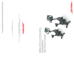
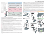
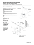
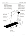
X9i Cross-Trainer
ASSEMBLY
INSTRUCTIONS
Congratulations...
and welcome to the world of
and the
Life Fitness
Life Fitness X9i Cross-Trainers
The following Parts List and the step by step assembly procedures have been assembled to
make the set-up of the Cross-Trainer as quick and easy as possible.
Please take special note of the following important points prior to choosing a location and
beginning assembly of the Cross-Trainer.
IMPORTANT SAFETY INSTRUCTIONS!
⇒
DO NOT locate the Cross-Trainer outdoors, near swimming pools, or in areas of high humidity.
⇒
DO NOT operate your Cross-Trainer if it has been dropped, damaged, or even partially
immersed in water. If this occurs, contact Life Fitness Customer Support Services at the number
in the Operation Manual.
⇒
DO NOT locate the Cross-Trainer any closer than 30 inches (76 cm ) to a television set.
⇒
DO NOT locate additional Cross-Trainers any closer than 42 inches (107 cm) from center to
center to avoid interference (cross talk) between Heart Rate monitors.
⇒
DO keep the area around your Cross-Trainer clear of any obstructions, including walls and
furniture. Ensure that there is at least a 12 inch (30cm) clearance in front of the Cross-Trainer.
⇒
DO verify the contents of the delivery carton against the accompanying Parts List prior to setting
the cartons and shipping material aside. If any parts are missing, contact Life Fitness Customer
Support Services at the number listed in the Operation Manual. Save the shipping cartons in
case of return.
⇒
DO read the entire Operation Manual prior to attempting to operate this machine as this is
essential for proper use.
CONSIGNES
DE
SECURITE IMPORTANTES!
⇒
NE placez PAS l'appareil à l'extérieur, près d'une piscine ou dans un endroit très humide
⇒
NE faites PAS fonctionner l'appareil s'il est tombé, s'il a été endommagé ou s'il a été
partiellement plongé dans l'eau. Si cela s'est produit, contactez le service après-vente de Life
Fitness au numéro fourni dans le manuel d'utilisation
⇒
NE placez PAS l'appareil à moins de 76 cm d'un poste de télévision
⇒
NE placez PAS d'autres appareils du même type à proximité. Un espace d'au moins 107 cm doit
être observé entre les parties centrales de deux appareils afin d'éviter les interférences entre les
contrôleurs de rythme cardiaque.
⇒
MAINTENEZ la zone autour de l'appareil libre de toute obstruction, y compris murs et meubles.
Veillez à laisser un dégagement d'au moins 30 cm devant l'appareil
⇒
VÉRIFIEZ si l'emballage contient toutes les pièces de la liste jointe avant de le mettre de côté.
Si des pièces sont absentes, contactez le service après-vente de Life Fitness au numéro indiqué
dans le manuel d'utilisation. Conservez l'emballage au cas où vous devriez renvoyer l'appareil.
⇒
LISEZ le manuel de l'utilisateur tout entier avant d'essayer de faire fonctionner cet appareil.
Ceci est indispensable à son utilisation correcte.
TOOLS REQUIRED FOR ASSEMBLY...
Magnetic #2 Bit Phillips Screwdriver, 5/16" & 3/16" Hex
Key Wrenches, 1/2" Open End Wrench
PARTS LIST
1
Hex socket Head Cap Screw
3/8-16 x 1”
0017-00101-1645
Qty: 8
2
Phillips Pan Head Screw
#8-18 x 10”
0017-00101-1744
Qty: 8
3
Phillips Pan Head Screw
#8-18 x 3/4”
0017-00101-1242
Qty: 14
4
Console Assembly
AK61-00193-0001
Qty: 1
5
Front Monocolumn Cover
0K61-06350-0003
Qty: 1
6
Back Monocolumn Cover
0K61-06351-0003
Qty: 1
7
Console Support Assembly
AK61-00500-0015
Qty: 1
8
Flat Washer
0017-00104-0192
Qty: 2
9
Left Front Cover
0K61-06200-0004
Qty: 1
10
Right Front Cover
0K61-06210-0004
Qty: 1
11
Left User Arm Assembly
AK61-00178-0002
Qty: 1
12
Right User Arm Assembly
AK61-00178-0001
Qty: 1
13
Front Rocker Cover
0K61-06340-0003
Qty: 2
14
Back Rocker Cover
0K61-06341-0003
Qty: 2
15
Foam Isolator (Polar® Receiver)
0K36-01059-0002
Qty: 1
16
Polar® Receiver
AK40-00045-0001
Qty: 1
17
Accessory Tray
0K63-01030-0001
Qty: 1
18
Internal Tooth Lock Washer
0017-00104-0450
Qty: 6
19
Cap: Console Support
0K61-01283-0001
Qty: 1
Step 1
Before proceeding, familiarize yourself with the parts of
the Cross-Trainer and make sure that you have
received all the items described in the Parts List.
Step 2
Locate the left and right FRONT COVER (#9, #10).
Usign two PHILLIPS PAN HEAD SCREWS (#3), mount
the USER LEFT FRONT COVER (#9) to the FRAME
(A). Attach the USER RIGHT FRONT COVER (#10) to
the FRAME in the same manner using two PHILLIPS
PAN HEAD SCREWS (#3). Secure the tops of the
FRONT COVERS together using two PHILLIPS PAN
HEAD SCREWS (#3).
Step 3
12
11
18
1
2PA
2PB
C
B
Locate the RIGHT USER ARM (#12). Snap the 2-PIN CONNECTOR (2PA) located at the bottom of the RIGHT USER ARM into
the 2-PIN CONNECTOR (2PB) positioned at the top of the RIGHT
ROCKER ARM (B). Feed the connectors and excess cable up into
the RIGHT USER ARM. Secure the RIGHT USER ARM to the
RIGHT ROCKER ARM using three HEX SOCKET HEAD CAP
SCREWS (#1) and INTERNAL TOOTH LOCK WASHERS (#18).
Repeat the procedure for the LEFT USER ARM (#11) and LEFT
ROCKER ARM (C). Tighten all screws securely.
CAUTION: BE CAREFUL NOT TO PINCH THE WIRE
HARNESSES WHEN ASSEMBLING THE USER ARMS
(#11 & #12) TO THE ROCKER ARMS (B & C).
MISE EN GARDE : VEILLEZ À NE PAS PINCER LE
FAISCEAU DE CÂBLES LORS DE L'ASSEMBLAGE
DES POIGNÉES MOBILES (Nº 11 et 12) ET DES BRAS
BASCULANTS (B ET C).
Step 4
Detach and unwrap the WIRE HARNESS (E) (10P, 3P, 4P) located at
the top of the MONOCOLMN (F). Holding the CONSOLE SUPPORT
ASSEMBLY (#7) with the handgrips facing upward, feed the WIRE
HARNESS up through the neck and out the top access hole. Carefully
lower the CONSOLE SUPPORT ASSEMBLY into the
MONOCOLUMN.
4P
3P
4
10P
CAUTION: BE CAREFUL NOT TO PINCH THE WIRE HARNESSES (E) WHEN ASSEMBLING THE CONSOLE SUPPORT ASSEMBLY (#7) TO THE MONOCOLUMN (F)
17
MISE EN GARDE : VEILLEZ À NE PAS PINCER LE FAISCEAU DE CÂBLES (E) LORS DU MONTAGE DU SUPPORT
19
DE LA CONSOLE (Nº 7) SUR LA COLONNE CENTRALE (F).
2
Step 5
Using two HEX SOCKET HEAD CAP SCREWS (#1) and two FLAT
WASHERS (#8), secure the CONSOLE SUPPORT ASSEMBLY (#7) to
the MONOCOLUMN (F). Tighten the screws securely.
2
Step 6
Locate the ACCESSORY TRAY (#17). Align the ACCESSORY TRAY
with the bottom of the DISPLAY CONSOLE (#4) as shown. Using four
MOUNTING SCREWS (#2), secure the ACCESSORY TRAY to the
DISPLAY CONSOLE as shown. Tighten the screws securely.
CAUTION: DO NOT OVER-TIGHTEN THE PHILLIPS HEAD
PAN SCREWS (#2).
MISE EN GARDE : NE SERREZ PAS TROP LES VIS CRUCIFORMES À TÊTE CYLINDRIQUE (Nº 2).
7
E
1
8
Step 7
F
Attach the 3-PIN (3P), 4-PIN (4P) and 10-PIN (10P) CONNECTORS to the
corresponding jacks on the back of the CONSOLE ASSEMBLY (#4).
Step 8
Feed any excess WIRE HARNESS (E) down into the CONSOLE SUPPORT ASSEMBLY (#7). Secure the
CONSOLE ASSEMBLY (#4) to the CONSOLE SUPPORT ASSEMBLY using four PHILLIPS PAN HEAD SCREWS
(#2). Tighten the screws securely.
CAUTION: DO NOT OVER-TIGHTEN THE PHILLIPS HEAD PAN SCREWS (#2).
CAUTION: BE CAREFUL NOT TO PINCH THE WIRE HARNESS (E) WHEN ASSEMBLING THE CONSOLE ASSEMBLY (#4) TO THE CONSOLE SUPPORT ASSEMBLY (#7).
MISE EN GARDE : NE SERREZ PAS TROP LES VIS CRUCIFORMES À TÊTE CYLINDRIQUE (Nº 2).
MISE EN GARDE : VEILLEZ À NE PAS PINCER LE FAISCEAU DE CÂBLES (E) LORS DU MONTAGE
DE LA CONSOLE (Nº 4) SUR SON SUPPORT (Nº 7).
Step 9
Locate and install the CONSOLE SUPPORT CAP (#21) onto the CONSOLE SUPPORT ASSEMBLY (#7) as
shown.
Step 10
Locate the POLAR RECEIVER (#16). Slide the
FOAM ISOLATOR (#15) over the POLAR
RECEIVER. Remove the POLAR RECEIVER
JACK (G) from the tape and plug the POLAR
RECEIVER into the POLAR RECEIVER JACK.
Step 11
Locate the front and back MONOCOLUMN
COVERS (#5 & #6). With the wire positioned
on top, carefully insert the POLAR RECEIVER
(#16) between the vertical ribs located inside
the BACK MONOCOLUMN COVER (#6).
Place the BACK MONOCOLUMN COVER (#6)
over the PIVOT SHAFT (H) at the top of the
MONOCOLUMN (F).
NOTE: THE POLAR RECEIVER WIRE MUST
BE POSITIONED ON TOP WHEN INSERTED
INTO THE REAR MONOCOLUMN COVER
(#6).
REMARQUE : LE FIL DU RÉCEPTEUR POLAR DOIT ÊTRE PLACÉ SUR LE DESSUS LORS DE
L'INSERTION DANS LE CACHE ARRIÈRE DE LA COLONNE CENTRALE (Nº 6).
Step 12
Place the FRONT MONOCOLUMN COVER (#5) on the opposite side of the BACK MONOCOLUMN COVER (#6)
to cover the PIVOT SHAFT (G) and CONSOLE SUPPORT ASSEMBLY MOUNTING SCREWS. Interlock the top
tabs and use two PHILLIPS PAN HEAD SCREWS (#3) to secure the bottoms of MONOCOLUMN COVERS
together. Tighten the screws securely.
CAUTION: DO NOT OVER-TIGHTEN THE PHILLIPS PAN HEAD SCREWS (#3).
MISE EN GARDE : NE SERREZ PAS EXCESSIVEMENT LES VIS CRUCIFORMES À TÊTE CYLINDRIQUE (Nº 3).
Step 13
Locate one FRONT ROCKER COVER (#13) and one BACK ROCKER COVER (#14). Position the FRONT
ROCKER COVER over the user side of the left end of the PIVOT SHAFT (H) (as shown) making sure that it
interlocks with the MONOCOLUMN COVERS (#5 & #6). Place the BACK ROCKER COVER over the
opposite side of the left end of the PIVOT SHAFT in the same manner. Secure the covers using three
PHILLIPS PAN HEAD SCREWS (#3). Repeat the procedure reversing front and back for the user right
end of the pivot shaft.
CAUTION: DO NOT OVER-TIGHTEN THE PHILLIPS PAN HEAD SCREWS (#3).
MISE EN GARDE : NE SERREZ PAS EXCESSIVEMENT LES VIS CRUCIFORMES À TÊTE CYLINDRIQUE (Nº 3).
PRE-OPERATION CHECKLIST
Ensure that all fastener are tight.
Make sure the CROSS-TRAINER is properly leveled and stable.
(Refer to the Operation Manual)
Ensure that the Leveler Jam Nuts are tight.
(Refer to the Operation Manual)
Read the entire Operation manual before using the Cross-Trainer.
LISTE DES VÉRIFICATIONS À EFFECTUER AVANT LA MISE EN MARCHE
Vérifiez si tous les dispositifs de fixation sont serrés
Vérifiez si l'APPAREIL D'EXERCICE POLYVALENT est de niveau et stable.
(Référez-vous au manuel d'utilisation.)
Vérifiez si les contre-écrous des vérins de mise à niveau sont serrés.
(Référez-vous au manuel d'utilisation.)
Lisez le manuel d'utilisation dans son intégralité avant d'utiliser l'appareil d'exercice
polyvalent.
Before attempting to operate your Cross-Trainer, it is imperative that you familiarize yourself with the
contents of the operation Manual. If your Cross-Trainer does not respond as described in the Operation
Manual, contact the nearest Life Fitness service center as listed in the Operation Manual.
Copyright 2002 Brunswick Corporation. All rights reserved. Life Fitness is a trademark of Brunswick Corporation.
Polar is a registered trademark of Polar Electro, Inc.
M051-00K61-A105
07/05