1
Service Manual
!"#$%&$'()**
Cat.-No.: 17901S/2
!
,-./%/01(2/%3(04(3!-(561762
No.
DATE / Rev. REVISION DESCRIPTION
1
01/2005-01
First edition
2
02/2005-08
Supplement: Technical diagrams
+
++
8013-13%
1. MECHANICAL ADJUSTMENTS
Reading Assembly
Sampling Arm
Cuvette Washing Arm
Photometer
Sample Tray
Reagent Plate
Diluters
Devices Required
2. ELECTRONICAL ADJUSTMENTS
3. OPERATIONS TO BE DONE WITH ANALYZER TURNED ON
4. UTILITY AND DIAGNOSTIC DISKETTE
5. TROUBLE SHOOTING GUIDE
6. HOW TO USE THE DIAGNOSTIC TESTER
%$9:&;(1<&:=
Analyzer may be contaminated with human material (blood, serum, plasma,
urine etc.) Disinfect analyzer prior to servicing and wear gloves. Be aware of
potential biohazardous risks!
3
3
6
8
9
10
11
12
13
14
16
16
17
21
3>+?(@$A:(B:9&(CB$DE
2/27
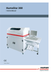
Service Manual HumaStar 300
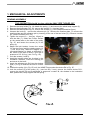
FG(5-8!61/862(6HI7%35-13%
,-6H/1J(6%%-5K2L
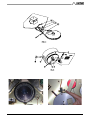
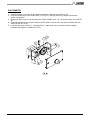
3!/%(0M-,63/01(?><"BN(C:(N<D:(O+&>(&>:(6162LP-,(37,1-H(044
1.
2.
3.
4.
Remove the lamp holder Fig. 1A: detach the spring (1) and remove the whole lamp support (2).
Remove the photometer Fig. 1B : remove the screws (1) ( hex key 3mm)
Remove the read window Fig.1C, remove the screws (1) ( use Phillips screwdriver 5mm)
Unscrew the knob (2), remove the reference pin (3). Remove the reaction plate. (To remove the
reaction plate use the reference pin by inserting it into one of the two holes (9) ). Remove cuvette
38 (use the extractor tool D/1)
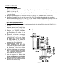
5. Tighten the screw (6) ( hex key 10mm) to
lock the disk (7). Insert the Friction Devise
on the central axis on the side of the pulley
Fig. 1E. and loosen the screws (4) of the
pulley (2).
6. Adjust the belt tension: loosen the screw
(2)( hex key 3mm) and the rotating screw (1)
- ( hex key 4 mm), rotate the support (3) (counterclockwise) to obtain a deflection in
the center of the belt of about 5 mm with a
pressure of 0.5 -0.6 kg. ( see 5 in Fig. 1D)
7. Lock the screws (1 and 2).
8. Install the reaction plate into its place in the
incubation chamber, insert the locking pin
and screw in the knob.
9. Insert the reference pin D/6 into the window
seat (1) in Fig.1E and into the hole of cuvette
38.
10. Position the pulley (2) in Fig. 1E until the HOME Flag touches the device D4 in Fig. 1E.
11. Lock the screws (4) of the pulley (2) - (use hex key 3 mm), remove the friction device D/11,
remove the device D6 and re-assemble in sequence: cuvette 38, the window in the incubation
bath, photometer, lamp support and the spring.
Service Manual HumaStar 300
3/27
4/27
Service Manual HumaStar 300
Service Manual HumaStar 300
5/27
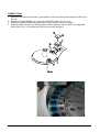
%65M2/1J(6,5
.-,3/862(50.-5-13
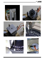
1. Remove the PCB of the encoder (1) in Fig. 1F and replace it with the device D/8 to align the
SYNC. (11) in Fig.1F.
2. Check all the screws of the pulley (3 and 4) in Fig. 1F and make sure that they are all well locked.
( hex key 2 mm)
3. Bring the probe support to 5 mm from the top (12) in Fig. 1F -(use the spacer 2 mm D/3)
4. Rotate the encoder disk (2) until the hole of the SYNC is perfectly aligned with the reference
device; lock the disk screw (13) ( hex key 1.5 mm. Make sure not to tighten too strongly since the
support is made in PVC) Reinsert the PCB of the encoder and lock the screws (5).
,0363/0162(50.-5-13
1. Remove the PCB of the encoder (6) and replace it with the device D/8 to align the SYNC (11) in
Fig. 1F.
2. Insert into cuvette 17 or 20 the
adapter device D/2, loosen the
screws of the pulley (8) in Fig.1F.
3. Position the PROBE (Sample
Reagent) perfectly perpendicular
on the opening of cuvette 17 or
18,
4. Introduce the Probe declogger
D/7 into the probe holder. ("A5"
L=205; "S300" L=178) and rotate
the pulley (8) in Fig.1F to align
the flag HOME to the center of
the OPTO (15) in Fig.1F.- lock the
screws (14) of the pulley (8).
5. Rotate the cam (9) in Fig. 1F (plain screwdriver 2.5 mm) and
verify that the probe rotates inside
the perimeter of the hole of the
adapter.
6. Hold the ARM fixed and rotate the
disk (7) until the hole of the SYNC
(11) is perfectly aligned with the
hole of device D/8 in Fig. 1F.
7. Lock the screws (14) of the disk
(use hex key 1.5mm - Make sure
D<&(&<(B<QE(&>:(?Q':O(&<<(&+A>&B;
since the support is made in PVC)
8. Reinsert the PCB of the encoder
and lock the screws (10).
6/27
Service Manual HumaStar 300
Service Manual HumaStar 300
7/27
87.-33-(R6%!/1J(6,5
1. Remove the arm (1) from the cuvette washing system holder
2. Insert device D/4 in Fig.1G on the OPTO switch (2) and position the FLAG (3) by rotating the
screw (4) until it touches the device D/4.
3. Remove from support (7) the probe (2) using the screw (10)
4. Insert the ARM (1) into its holder and adjust its height to 119 mm ( use device D/9) in Fig.1G and
lock loosely the screws (8) - (use hex key 2.5mm)
5. Insert adapter device D/2 into cuvette 1 in Fig. 1G.
6. Lower the ARM (by rotating the screw (4) manually) and align it perfectly to the center of the
adapter.
7. Lock the screws (8) - (hex key 2.5mm) and screws (9) - ( hex key 3mm) in Fig, 1G.
8. To center the second PROBE, raise the ARM and insert the adapter device D/2 into the cuvette 2.
9. Insert the PROBE 2 , lower the arm (7) and center the Probe perfectly over the adapter and lock
the screws (10) - (using a Phillips screwdriver 5mm) Fig.1G.
8/27
Service Manual HumaStar 300
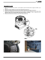
M!0305-3-,
1. Stretch the belt (1) to have in its middle a deflection of about 2mm with 0.5 kg.
2. Lock the grub screw of the SYNC disk (7) in Fig.1H ( hex key 2mm) in a way to have some
friction on the disk.
3. Rotate the filter revolver (3) and place the FLAG HOME (4) in Fig. 1H to the center of the OPTO
(5).
4. Hold still the filter revolver and rotate the SYNC disk until one of the two slits coincides with the
center of the OPTO (6).
5. Lock the disk grub screw (7) - ( hex key 2mm - make sure not to lock the screw too tightly
because the support is made from PVC)
Service Manual HumaStar 300
9/27
%65M2-(3,6L
1. Remove the PCB of the encoder (1) and replace it with the device D/8 to align the SYNC.(5) in
Fig. 1N.
2. Position the FLAG HOME in the center of the OPTO switch (4) in Fig. 1/N.
3. Rotate the SAMPLE ARM and position the PROBE into the center of sample 1.
4. Rotate the disk until the hole off the SYNC coincides perfectly with the hole of the alignment
device D/8 in Fig. 1/N, replace the PCB of the encoder and lock it.
10/27
Service Manual HumaStar 300
,-6J-13(M2631. Remove the PCB of the encoder (1) and replace it with the device D/8 to align the SYNC. (2) in
Fig. 1L.
2. Position the FLAG HOME (3) in the center of the OPTO switch (4)
3. Rotate the Reagent Arm and position the PROBE in the center of Reagent container 1.
4. Rotate the encoder disk (2) until the hole of the SYNC coincides perfectly with the hole of the
reference device D/8. Lock the grub screw of the disk (2) - ( hex key 1 -5mm - make sure not to
tighten the screw too strong because the support is made from PVC).
5. Reinsert the PCB of the encoder (1) and lock it with screws (5).
Service Manual HumaStar 300
11/27
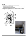
H/273-,%
1. Unscrew just a little the SYNC disk (1) in Fig. 1M so it can be moved
2. Verify that all the screws of the pulley ( 2 and 3) in Fig 1M are locked well. ( hex key 2mm) and
stretch the belt (7) by pulling the motor (8).
3. Insert the spacer device D/10 (29mm) between the female screw (9) and the upper support (4) in
Fig. 1M and lock it by rotating the screw (5) manually.
4. Rotate the SYNC disk until the slit coincides perfectly with the center of the OPTO (10).
5. Lock well the screw of the disk (6) – (hex key 2mm - make sure not to tighten the screw too
strong, because the support is made from PVC)
12/27
Service Manual HumaStar 300
H-./8-%(,-S7/,-H
3<<B(T+&(8$&GU1<G(FVWV*
D/1 - Cuvette extractor
D/2 – Device to center all Probes: Sample, Reagnt and cuvette washing probes)
D/3 - Spacer 2 mm to Home Sample and Reagent Arms
D/4 - Device to align HOME position for Reaction plate and cuvette-washing Arm .
D/5 - Alignment to center Probe
D/6 – Device to align Reaction Plate and Reagent Probes
D/7 - Probe declogger
D/8 - Alignment SYNC of Encoder disk
D/9 - Spacer to adjust the cuvette washing Arm
D/10 - Spacer to adjust HOME diluter
D/11 – Friction Device for pulley for reaction plate (with spring)
6NN&+<D$BB;(':X"+':N(&<<B?(D<&(@'<Y+N:N(O+&>(&<<B(E+&
D/12 - Hex Key - 1.5, 2, 2.5, 3 and 4 mm
D/13 - Hex Key - 2
D/14 - Hex Key - 2.5
D/15 - Hex Key – 3
D/16 - Hex Key - 4
D/17 - Tube hex key – CH 10
D/18 - Phillips screwdriver D= 5 mm
D/19 – Normal screwdriver D= 2.5 mm
D/20 - Normal screwdriver D= 7 mm
Service Manual HumaStar 300
13/27
ZG -2-83,01/862(6HI7%35-13%
1. Power Supply Board Cat.-No. 17970/7 (EB0043.01)
1.1
Water Bath Temperature
This operation should be done at least 20 minutes after the analyzer has been turned ON.
Dispense 500 ul of dist. water into one of the cuvettes in the reaction plate.
1.2
Introduce a thermometer into that cuvette and wait about 10 sec. before starting to read the
temperature (use a thermometer with a small thermocouple not to distort the measurement).
The incubation temperature should reach 37°C +/- 0.2°C
1<&:: the temperature displayed by the software in MAINTENANCE is about 3°C higher because
it is measured inside the heater.
1.3
If the temperature needs to be adjusted the heater can be adjusted by means of
potentiometer PR26. 1 complete rotation cw = + 1°C.
1.4
The reference voltage has to be +5V at testpoint TP5 and can be adjusted by means of
PR47.
1.5
Reagent Cooling Temperature
The reagent cooling is not controlled by any sensor. The cooling is sufficient to reduce the
temperature of the reagent to about 12°C below room temperature.
1.6
The maximum cooling effect can be adjusted by means of PR48.
2.
DC/DC Converter for Lamp Cat.-No. 17970/10 (EB0054.01)
2.1
Adjust with PR1 11V to be measured at TP3 (or lamp connector J2).
3.
Motor Driver Boards
17970/20
EB0092.02
17970/21
EB0092.03
17970/22
EB0092.04
17970/23
EB0092.05
All the above boards have 2 different currents: Low Power (hold) and Working Power (move).
To make the adjustment the board has to be connected to an extender cable.
All measurements are made at TP3 against GND.
3.1
3.2
3.3
3.4
14/27
17970/20 adjust by means of PR2 (low power) to 400mV, PR1 (work) to 800mV
17970/21 adjust by means of PR2 (low power) to 215mV, PR1 (work) to 800mV
17970/22 adjust by means of PR2 (low power) to 100mV, PR1 (work) to 400mV
17970/23 adjust by means of PR2 (low power) to 100mV, PR1 (work) to 800mV
Service Manual HumaStar 300
4.
ADC Converter Cat.-No. 17970/19 (EB0089.01)
4.1
4.2
Be sure the water bath is filled and fill cuvette # 38 with 600 µl distilled water.
With the help of the service program TESTER move filter 340 nm into the reading position.
On the ADC board one should measure +0.8 to 1.3 V at TP2
If this range is not reached please check these points:
a) No water in water bath or cuvette
b) Cuvette tray not correctly adjusted
c) Lamp aged or burned
d) Filter dirty or aged
e) Optical detector defect
4.3
Check whether +4.2 to 4.5 V are available on TP3. If not adjust to this range with PR1 (Gain).
5.
Peristaltic Pump Driver Board
17970/4
EB0033.01
17970/5
EB0033.02
17970/6
EB0033.03
5.1
Pump P1 & P2
In reference to TP1 adjust the voltage to 800mV with PR1.
5.2
Pump P4
In reference to TP2 adjust the clock to 66.0 Hz with PR2.
In reference to TP1 adjust the voltage to 500mV with PR1.
5.3
Pump P5
In reference to TP2 adjust the clock to 1.0 KHz with PR2.
In reference to TP1 adjust the voltage to 500mV with PR1.
Service Manual HumaStar 300
15/27
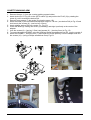
)G(0M-,63/01%(30(K-(H01-(R/3!(6162LP-,(37,1-H(01
1. Filling the HYDRAULIC SYSTEM
2. Filling the incubation bath chamber
3. Lamp alignment
4. Check all module alignment
5. Check peristaltic pumps
6. Check diluters
[G(73/2/3L(61H(H/6J10%3/8(H/%T-33\3<("?:(&>:(&>+?(@'<A'$#(&>:(M8(>$?(&<(C:(01]
1) Turn ON the analyzer. When the display window appears - press and hold CTRL key
2) Insert the 7&+B+&;(H+?E:&&:(and proceed to the Menu (^5;(8<#@"&:'_(`(Select floppy(^6_G
3) The diskette offers the following programs:
a) M'+D&5:&>.exe
- extracts the Methods from DB and copies them into the file methods.txt
b) %$&?#+&>.exe
- to enable and disable the $"&<'"D, ?>"&N<OD and to #<N+9;(&>:(@$??O<'Na(set the(B:Y:B
?:D?<'(sensitivity, select the liquid for blank and change the !0%3(C$"N('$&:
c) %$Y:HK8>:#G:b:
U((serves to save and to reinstall the methodologies - '"D(9'<#(9B<@@;(N+?E(<DB;
d) 3:?&:'Gexe
! diagnostic TESTER software
e) 3:?&B<<E.exe
- special tool to reset the TESTCOUNTER and close reagent tray positions and method
settings – '"D(9'<#(9B<@@;(N+?E(<DB;
16/27
Service Manual HumaStar 300
cG(3,07K2-%!003/1J(J7/HcGF((6162LP-,((H0-%(103(37,1(01
a) Make sure the power cord is inserted
b) Verify if there is power
c) Unplug the power cord and check the fuses
cGZ((47%-%(K20R(-6%/2L
a) Unplug all the connectors from the power supply PCB, replace the fuses and turn ON the
analyzer
b) If the 9"?:? continue to CB<O – replace the power supply
c) If the 9"?:?(N<(D<&(CB<O - check all the voltages on the power supply PCB. If they are
correct – insert the connectors one by one in order to isolate the defective part.
cG)((3!-(M8(J,07M
cG)GF((3!-(805M73-,(H0-%(103(37,1(01
a) Make sure there is power on the power supply
b) Check if the fan is turning
c) Check the following
cG)GZ((3!-,-(/%(10(M0R-,
a) Check the fuse
b) Make sure there is power
cG[((M!0305-3-,
cG[GF(3!-(M!0305-3-,(265M(/%(044
a) If computer and instrument are ON – change Lamp
b) Before changing the lamp – check the output voltage from power supply ( 11 Volt)
cGc((/187K63/01(K63!
cGcGF(3!-(K63!(3!-,50%363(/%(103(!-63/1J
a) Check if there is voltage on its connector
b) Check the continuity of the heating element (about 40 Ohm)
c) Check if there is voltage on the control pin of the Opto switch
cGcGZ(3!-(K63!(3!-,50%363(/%(0.-,(!-63/1J
a) Verify the operating circuit that controls the temperature
b) Check the O-ring holding the thermometer inside the thermostat
cGcG)(2/S7/H(/1%/H-(3!-(/187K63/01(8!65K-,(/%(103(8/,87263/1J
a) Make sure that pump “P6” is working properly
b) Check the recycling valve “V4”
cGcG[(3!-(R6%3-((H-./8-(H0-%(103(-5M3L
a) Make sure that pump “P7” is working properly
b) Check the pump tubing
Service Manual HumaStar 300
17/27
cGcGc(M75M(^MF_(H0-%(103(R0,T(\(%$#@B:]
a) Make sure the rotor is not blocked
b) Check the fuse
cGd((,-%723%
cGdGF(101(,-M,0H78/K2-(,-%723%
a) Make sure that the liquid inside the bath is clean, empty and refill with clean
b) Check all tubing connections (Sampling probes, Cuvette washing probes, peristaltic
pumps, syringes)
c) Check the syringe pistons “D1 and D2” and their O-rings and make sure all is tightly held
d) Check the connections and the tubing in pumps P1 and P2
e) Check – if necessary change the photometer lamp
f) Check reagent and sample volumes and the method used
g) Make sure that the Reagent 1 volume is at least 300 µl
h) Make sure to use fresh reagents
i) Make sure that the reagent containers are clean
j) Do not add fresh Enzyme Reagent into the old one
k) Make sure to use fresh WASH SOLUTION ( that washes the sampling probes and the
cuvettes)
l) Make sure that the probe mixers are working properly
cGdGZ(K6H((2/1-6,/3L
a) Check the lamp alignment
b) Make sure that the signal output from the pre-amplifier is correct
c) Check volumes of Sample and Reagent for that method
cGdG)(,-%723%(0K36/1-H(6,-(300(!/J!
a) Re-standardize and /or re-calibrate all your methods
b) Check the parameters of your methods
c) Old standards or calibrators – get new ones
d) Check the factors
cGdG[(,-%723%(0K36/1-H(6,-(300(20R
a) See the ABOVE IN 3.
b) Check the temperature in the incubation bath
c) Make sure your reagents and standards are fresh
d) Re-standardize the method
cGdGc(%-,75(8013,02%(6,-(103(R/3!/1(-eM-83-H(,61Ja) Check controls for expiration date and correct lot number
b) Check method, it may have been inadvertently reprogrammed
c) Make sure that method conforms with reagent suppliers specifications
d) Make sure the controls are not deteriorated
e) Re-assay by an alternative system, method or different reagent
f) If substrates – recommend to re-standardize analyzer using fresh primary standards or
calibrators
g) Dirty solution in the incubation bath – exchange solution
h) Make sure that the incubation bath is at 37°C
i) If enzyme kinetics - check FACTOR and make sure that it corresponds to the reagent
suppliers' specifications.
18/27
Service Manual HumaStar 300
cGdGd(801365/163/01
a) Make sure to use fresh WASH solution
b) Missing WASH solution
c) Old WASH solution with deposits
d) Make sure no drops are hanging on the bottom of the Sample Probe when going to aspirate the
sample or after
e) Make sure there no drops are hanging on the Reagent Probe after reagent aspiration or
dispensing
f) Make sure that the two probes that wash the cuvettes work properly ( go all the way down dispense and aspirate correctly)
g) Make sure that the cuvettes are clean. Suggest to wash them with a biological glass detergent
used in the laboratory.
h) Check the cuvettes after a washing cycle and make sure that they are dried properly. To do so,
use a micropipette with a thin tip and aspirate from the bottom; there should be no liquid
i) If running many turbidity tests – suggest to wash the cuvettes right afterwards with a mild acidic
solution or any other solution that cleans the turbidity from the cuvettes. Also the cuvette
washing is very effective (see special note below)
cGdGV(H,/43
a) Check the stability of the photometer lamp
b) Change photometer lamp
c) Check stability of the incubation bath
d) Make sure the reagents are fresh
cGdGf(2/S7/H(H,0M%(01(3!-(3/M(04(3!-(M,0Ka) Make sure that all connections to the Probes are really tight
b) Check both syringe pistons and their O-rings
c) Check the connections of the peristaltic pumps “P1and P2”
d) Make sure that the air scrub inside the Probe cleaner works properly
cGV(5/e-,%
a) Check the voltage on the motor
b) Make sure that the connecting rod moves correctly by rotating the cam with a screwdriver
c) Make sure that the motor resistance is (about 10 Ohm) when disconnecting it from the PCB
cGf(M,/13-,
cGfGF((M'+D&:'(N<:?(D<&((37,1(01
a) Make sure that the power cord is plugged in
b) Check the ON/OFF switch
c) Check the fuse
cGfGZ((M'+D&:'(N<:?(D<&(M'+D&(01U2/1a) Make sure the printer is set ON-LINE
b) Make sure the Check Box in 0@&+<D?(is :D$CB:N to print on-line
c) Check Printer cable connection
cGfG)((M'+D&:'(N<:?(D<&(M'+D&(M$&+:D&(,:@<'&?(<'(0&>:'(M'+D&U0"&?
a) Make sure that the Check Box in 0@&+<D? is N+?$CB:N(to print On-Line
b) Make sure it is connected to the analyzer
Service Manual HumaStar 300
19/27
cGW(H/273-,
cGWGF(H+B"&:'(5<N"B:(%&<@?
a) Check with TEST the Diluter
b) Try to lubricate the screw with very thin oil
c) Change Syringe
cGWGZ((H+B"&:'(N<:?(D<'(6?@+'$&:(<'(H+?@:D?:
a) Squeezed or torn Syringe Tubing
b) Loose or badly connected Probe
c) Blocked Probe - clean
d) Wash Solution Container Empty – check
cGF*((2-.-2(%-1%0,%
cGF*GFG(2:Y:B(%:D?<'(&<<(%:D?+&+Y:
a) Probe stops above the liquid (Reagent container or sample cup) and does not go down
to aspirate.
b) Check sensitivity program and adjust accordingly
cGF*GZG(2:Y:B(%:D?<'(D<&(%:D?+&+Y:(:D<"A>
a) The Probe goes down into the liquid without sensing the liquid
b) Check sensitivity program and adjust accordingly
cGF*G)(K'<E:D(8<D&$Q&(C:&O::D(&>:(M'<C:($DN(+&?(M8K
a) The Probe goes all the way down into the liquid (Reagent or Sample) and gives error –
NO Reagent or Sample
b) Make sure that the connection between the PBC and the Probe is good
cGF*G[(K$N(+?<B$&+<D(C:&O::D(&>:(M'<C:($DN(&>:(#+b:'(#<&<'
a) Probe goes down and stops above the liquid without further going down
b) Make sure there is an isolation O-ring between the probe holder and the mixer motor
20/27
Service Manual HumaStar 300
dG(!0R(30(7%-(3!-(H/6J10%3/8(3-%3-,
The Hardware architecture of the ANALYZER is controlled by a Master Hardware (PC) and 3
slave Microprocessors. Each of these Microprocessors controls one of the robotic systems, as
follows:
F]( ,:$A:D&(%;?&:#
Z]( %$#@B:(%;?&:#
)]( ,:$Q&+<D(%;?&:#($DN(Q"Y:&&:(O$?>+DA
,:$A:D&(%;?&:#
3>:(9<BB<O+DA(N+$AD<?&+Q(&:?&?(Q$D(C:(:b:Q"&:N($?(?><OD(+D(4+A(tester1.bmp
Home Z – axis
Movement Z – axis
Test Z
Home Plate
Test Plate
Home Reagent Arm
Rotation Reagent Arm
Test Reagent Arm
Home Diluter
Diluter Movement
Test Diluter
Air Pump
Pump P4
Pump P2
Mixer
Level Sensor
Bar Code Reader ( Optional)
%$#@B:(%;?&:#
3>:(9<BB<O+DA(N+$AD<?&+Q(&:?&?(Q$D(C:(:b:Q"&:N($?(?><OD(+D(4+AG(tester1.bmp
Home Z – axis
Movement Z – axis
Test Z
Home Sample Tray
Test Tray
Home Sample Arm
Rotation Sample Arm
Test Sample Arm
Home Diluter
Diluter Movement
Test Diluter
Air Pump
Pump P4
Pump P1
Mixer
Level Sensor
Bar Code Reader ( Optional)
Service Manual HumaStar 300
21/27
,:$Q&+<D(%;?&:#
3>:(9<BB<O+DA(N+$AD<?&+Q(&:?&?(Q$D(C:(#$N:($?(?><OD(+D(4+AG(tester1.bmp
Cuvette Washing System
Home Z – axis
Movement Z - axis
Test Z – axis
Cuvettes
Home Plate
Rotation Plate
Test Plate
Home filter Revolver
Rotation Filter Revolver
Test Filters
Air Pump
Valve V4
Valve V5
Pump P3
Pump P5
Pump P6
Pump P7
Pump P8
Thermostat Temperature
Check AUX sensor
Check Waste Sensor
Test Photometer
Test ISE ( optional)
Level Test
22/27
Service Manual HumaStar 300
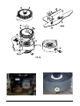
2$#@(6B+AD#:D&
1. First of all make sure that the measurement plate is correctly adjusted as outlined in the section
Mechanical Adjustments and the optical unit is mounted well.
2. Switch on instrument
3. Wait for Bios power on self test
4. As soon as Windows starts press the “CTRL” key down until the Windows desktop appears. Hold
it down till Windows has been completely loaded.
5. Insert floppy disk with “TESTER.EXE” and run it.
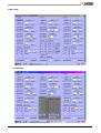
6. With reference to picture “tester0.bmp”, the screen is divided in 3 areas “Reagents”, “Cuvettes”,
“Samples”. For this alignment we will use the central area, that is “Cuvettes”. Every time a button
is pressed, the “Cuvette” sign will go from black to red. It will become black again as soon as the
requested operation is completed.
7. Press “Cuvettes” MO'(0D, wait till operation is completed.
8. Press “Cuvettes” !<#:(P, wait till operation is completed.
9. Press “Cuvettes” !<#:(MB$&:, wait till operation is completed.
10. Press “Cuvettes” !<#:(4+B&:', wait till operation is completed.
11. Check Thermal Bath level pressing “Cuvettes” 2:Y:B?, if both “TB Low” and “TB High” are green
then proceed to next; if not press “Cuvettes” 3K(4+BB, wait till operation is completed. Repeat this
step until the thermal bath is ok.
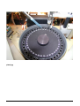
12. With reference to picture “plate0.jpg”, if cuvette 38 is not in front of the photometer, slowly move it
(manually) to position it in front of the photometer then fill cuvette 38 with 500 uL of distilled water.
13. Press “Cuvettes” 4<&<#:&:', a new window appears (picture “tester2.bmp”).
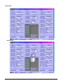
14. Press “Cuvettes” R$&:'(K, (picture “tester3.bmp”), wait till operation is completed. At the end of
this operation the water blank readings will be shown in the Water B. column.
15. Select (“Cuvettes” 4+B&:'(F, (picture “tester4.bmp”).
16. Press “Cuvettes” 5<Y:(4+B&:', wait till operation is completed.
17. Check the check box on the right of “Cuvettes” ,:$N(0D:, (picture “tester5.bmp”) to enable
continuos photometer reading.
18. Press “Cuvettes” ,:$N(0D:, from now on, the cuvette 38 is read continuosly with filter 1, and
readings are shown in the Readings column (picture “tester6.bmp”).
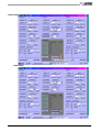
19. Adjust the lamp until you get the maximum reading.
20. De-check the check box on the right of “Cuvettes” ,:$N(0D:, (picture “tester4.bmp”) to disable
continuous photometer reading.
21. Repeat steps 14, 15, 16.
22. Press “Cuvettes” ,:$N(0D:, then read and store the mAbs.
23. Press “Cuvettes” !<#:(MB$&:, wait till operation is completed.
24. Repeat steps 14, 15, 16.
25. Press “Cuvettes” ,:$N(0D:, then read and compare the mAbs with values previously stored. If
read value is within ! 25 mAbs, then procedure is completed, if not, start it up again.
Service Manual HumaStar 300
23/27
@B$&:*Gg@A
24/27
Service Manual HumaStar 300
&:?&:'FGC#@
&:?&:'ZGC#@
Service Manual HumaStar 300
25/27
&:?&:')GC#@
&:?&:'[GC#@
26/27
Service Manual HumaStar 300
&:?&:'cGC#@
&:?&:'dGC#@
Service Manual HumaStar 300
27/27
!"#$:
All technical diagrams are available in hardcopy only. To order the complete service manual !"#$% 17901S/2
kindly contact [email protected].
Service Manual HumaStar 300
Human
Gesellschaft für Biochemica
und Diagnostica mbH
Max-Planck-Ring 21 " D-65205 Wiesbaden
Germany
Telefon:
+49 6122 9988 0
Telefax:
+49 6122 9988 100
eMail:
Internet:
02/2005-08
[email protected]
http://www.human.de