1
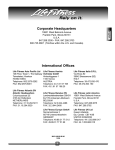
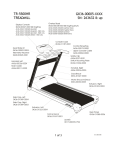
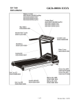
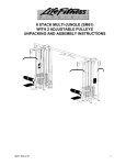
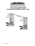
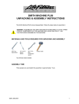
TREADMILL
INSTALLATION INSTRUCTIONS
Congratulations...
and welcome to the world of
and the Life Fitness 8500 treadmill.
The following Parts Identification Listing and the step by step installation
procedures have been assembled to make the set-up of your aerobic trainer as
quick and easy as possible.
Please take special note of the following important points prior to choosing a
location and beginning assembly of the treadmill…
S A F E T Y F I R S T !
⇒
DO NOT position the rear of the treadmill within 3 feet ( 1 meter ) of the nearest obstruction.
Life Fitness recommends a clearance of 6 feet ( 2 meters ) at the rear of the treadmill. The
sides of the treadmill should maintain a minimum clearance of 8 inches
( 21 cm ) from the nearest treadmill or other obstruction.
⇒
DO NOT locate the treadmill any closer than 30 inches ( 76 cm ) to a television set.
⇒
DO NOT locate the treadmill outdoors, near swimming pools, or in areas of high humidity.
⇒
DO verify the contents of the delivery carton against the accompanying parts listing prior to
setting the cartons and shipping material aside. If any parts are missing, contact Life Fitness
Customer Support Services at the number listed on the back page of this installation
instruction booklet. Save the shipping cartons in case of return.
⇒
DO read the entire Operation Manual prior to attempting to operate this machine as this is
essential for proper use. The Manual explains how to properly use the treadmill and helps you
to design an aerobic workout tailored to your personal fitness needs or requirements.
⇒
Ne Jamais Placer l'arrière de l'exerciseur à moins de 3 pieds (1 mètre) de l'obstacle le
plus près. Life Fitness recommande un espace libre de 6 pieds (2 mètres) à l'arrière de
l'exerciseur.
⇒
Le Life Fitness 8500 doit être installé à 8 pouces (20 cm) d'un autre exerciseur et à 30
pouces (76 cm) d'une télévision.
⇒
Ne pas uti l i ser l’exerciseur à l’extérieur, à proxim ité des piscines ou dans des lieux ou
l’hum idité est élevée.
Avant de commencer l'assemblage et de jeter les matériaux d'emballage, comparer le
contenu avec la liste des pièces comprises. S'il manque des pièces, appeler le service de
soutien Le Services Life Fitness Customer Support (É.-U.) en composant le 1-800-351-3737 ou
le 1-847-451-0036, ou le Life Fitness Europe, Munich, Germany, en composant le
49.89.310.6078. Sauvegarder les boîtes d'emballage en cas de renvoi.
⇒
Avant de faire fonctionner l'appareil Life Fitness 8500, il est nécessaire de lire tout le
guide de fonctionnement. Celui-ci explique comment utiliser correctement le l'exerciseur et
facilite l'élaboration d'un programme d'entraînement aérobique adapté à vos besoins de
conditionnement personnels.
TOOLS REQUIRED FOR ASSEMBLY... Phillips screwdriver, Hex key wrench set
PARTS DESCRIPTION
1
3
5
7
9
11
13
15
17
19
DISPLAY CONSOLE ASS’Y
AK45-00036-0001
DISPLAY CONSOLE SCREWS
0017-00101-1148
HANDLEBAR ASSEMBLY
AK36-00019-0002
HANDLEBAR WASHERS
0017-00104-0005
LEFT HANDRAIL
AK36-00056-0004
HANDRAIL BOLTS
0017-00101-1235
HANDRAIL SCREWS
0017-00101-1210
HANDRAIL SIDE CAP (RIGHT)
0K36-1089-0005
ENDCAP
0K36-01085-0004
TINNERMAN CLIP
0017-00103-0185
Qty: 1
2
Qty: 4
4
Qty: 1
6
Qty: 6
8
Qty: 1
10
Qty: 4
12
Qty: 4
14
Qty: 1
16
Qty: 1
18
Qty: 2
20
CENTER SUPPORT
AK36-00072-0000
CENTER SUPPORT SCREWS
0017-00101-1007
HANDLEBAR SCREW
0017-00101-1380
STOP KEY
AK36-00027-0002
RIGHT HANDRAIL
AK36-00056-0003
HANDRAIL WASHERS
0017-00104-0044
REMOVEABLE RIVET
0017-00042-0870
HANDRAIL SIDE CAP (LEFT)
0K36-1089-0006
ENDCAP SCREWS
0017-00101-1159
WAX KIT
GK45-00002-0001
Qty: 1
Qty: 4
Qty: 6
Qty: 1
Qty: 1
Qty: 4
Qty: 4
Qty: 1
Qty: 6
Qty: 1
Step 1
Untie and uncoil the WIRE HARNESS attached to the
front, right side of the treadmill. Pull gently on the
HARNESS to remove any slack.
Step 2
Place the RIGHT HANDRAIL next to the treadmill and
feed the WIRE HARNESS CONNECTOR into the slot
located at the bottom of the RIGHT HANDRAIL (#10) until
it exits through the top opening.
Step 3
Position the RIGHT HANDRAIL (#10) in place on the treadmill
FRAME and align the mounting holes in the HANDRAIL with those in
the FRAME. Insert the two HANDRAIL BOLTS (#11) and WASHERS
(#12) through the HANDRAIL and into the FRAME to secure it.
Tighten these BOLTS until snug, then loosen both BOLTS two
complete revolutions counter-clockwise. Repeat this step for the
LEFT HANDRAIL (#9).
NOTE: The HANDRAIL BOLTS (#11) must be loose at this time to facilitate the assembly of the HANDLEBAR
ASSEMBLY (#5) and the CENTER SUPPORT (#2).
CAUTION! BE CAREFUL NOT TO PINCH WIRES BETWEEN THE RIGHT HANDRAIL AND THE UNIT FRAME.
REMARQUE! FAIRE ATTENTION DE NE PAS PINCER LES FILS LORSQU’ON ABAISSE LA MAIN COURANTE
Step 4
Snap together the male and female 10-PIN CONNECTORS protruding
from the top of the RIGHT HANDRAIL (#10) and the underside of the
HANDLEBAR ASSEMBLY (#5). Once connected, feed the excess
cable carefully back into the top of the HANDRAIL. Rest the
HANDLEBAR in position on the VERTICAL HANDRAILS and install the
six SCREWS (#6) and WASHERS (#7) to secure the HANDLEBAR
ASSEMBLY to the two VERTICAL HANDRAILS.
Step 5
Snap the 10-PIN CONNECTOR protruding from the top of the
HANDLEBAR ASSEMBLY (#5) into the
1 3
corresponding CONNECTOR in the back of the
X
DISPLAY CONSOLE (#1). Snap the 6-PIN
CONNECTOR of the extended memory board wire
4 2
harness (located in the display console bracket)
into the corresponding CONNECTOR in the back of the
DISPLAY CONSOLE. Install the four SCREWS (#3) in a crisscross pattern to secure the DISPLAY CONSOLE to the
HANDLEBAR ASSEMBLY.
Step 6
Place the
HANDRAIL CENTER SUPPORT into position between the two
HANDRAILS and secure it with the four CENTER SUPPORT SCREWS
(#4).
Step 7
Secure the bottom sides of the HANDRAILS to the angled FRAME
BRACKETS using two SCREWS (#13) for each HANDRAIL.
THE SCREWS (#13) MUST BE FIRMLY TIGHTENED BEFORE TIGHTENING THE HANDRAIL BOLTS (#11) TO
INSURE PROPER STABILITY OF THE UPPER TREADMILL.
Step 8
Tighten the HANDRAIL BOLTS (#11) securing the base of each of the VERTICAL
HANDRAILS to the FRAME of the treadmill.
Position the right (#15) and left (#16) HANDRAIL SIDE CAPS into place on the
corresponding HANDRAILS and secure each with two REMOVEABLE RIVETS (#14).
Step 9
Insert the two TINNERMAN CLIPS (#19)
into the slots as shown below. Check
that the holes in the extrusion align with
the holes in the TINNERMAN CLIPS. Set
the ENDCAP (#17) into position and
secure in place with the six ENDCAP
SCREWS (#18).
Step 10
Open the WAX KIT (#20) and install the WAX according to the directions provided on the Instruction Sheet enclosed
within the WAX KIT.
WARNING: DO NOT OPERATE THE LIFE FITNESS 8500 TREADMILL PRIOR TO INSTALLING THE WAX
ACCORDING TO THE INSTRUCTIONS ENCLOSED WITHIN THE WAX KIT. FAILURE TO INSTALL THE WAX
PRIOR TO USE MAY CAUSE DAMAGE TO THE UNIT AND VOID YOUR WARRANTY.
MISE EN GARDE: VOUS DEVEZ METTRE DE LA CIRE CONFORMÊMENT AUX INSTRUCTIONS COMPRISES
AVEC LE NÊCESSAIRE DE CIRE AVANT DE FAIRE FONCTIONNER L’EXERCISEUR DE MARCHE LIFE
FITNESS 8500. LE FAIT DE NE PAS METTRE DE CIRE AVANT D’UTILISER L’APPAREIL POURRAIT
ENDOMMAGER L’EXERCISEUR ET ANNULER LA GARANTIE.
Step 11
The treadmill STRIDING BELT is properly centered at the factory however, the Life Fitness 8500 treadmill must be
leveled in the location it is to be used. After placing the treadmill in its intended location for use, check the stability of
the unit. If the unit is not stable, turn the LEVELING LEGS clockwise or counterclockwise until the rocking motion is
diminished.
IT IS EXTREMELY IMPORTANT THAT THE TREADMILL BE CORRECTLY LEVELED FOR PROPER
OPERATION. AN UNSTABLE UNIT MAY CAUSE STRIDING BELT MISALIGNMENT.
IL EST EXTRÊMEMENT IMPORTANT QUE L'EXERCISEUR SOIT DE NIVEAU POUR UN FONCTIONNEMENT
ADÉQUAT. UN APPAREIL INSTABLE RISQUE DE DÉSALIGNER LA COURROIE DE MARCHE.
Step 12
Insert the STOP KEY (#8) into the slot on the front of the
HANDLEBAR ASSEMBLY (#5).
Plug the machine POWER CORD into a properly grounded
ELECTRICAL outlet.
Insert the SAFETY KEY into the POWER SWITCH (near the
POWER CORD) and toggle it to the “ON” or “I” position.
The Safety key can be removed to prevent unauthorized use.
Step 13
Begin a program, but DO NOT begin running. It is important to
insure that the STRIDING BELT remains centered during operation.
If the BELT drifts to the right, see Figure A. If the BELT drifts to the
left, see Figure B.
NOTE: WHEN ADJUSTING THE STRIDING BELT YOU MUST ADJUST BOTH SIDES EQUALLY.
(E.G. ADJUST THE LEFT SIDE 1/4 TURN CLOCKWISE AND THE RIGHT SIDE 1/4 TURN COUNTER-CLOCKWISE)
OPERATION CHECKLIST
⇒
⇒
⇒
⇒
Make sure the HANDLEBAR and HANDRAIL BOLTS are tight.
Make sure the STRIDING BELT is properly centered or tracked.
Check the operation of the STOP KEY.
Check to insure that the POWER CORD is not located beneath
or alongside the machine.
⇒ Read the entire Operation Manual before attempting to operate the treadmill
⇒ Check to insure the WAX KIT was installed prior to operation.
ENGLISH / METRIC DEFAULT SETTING TOGGLE
The default setting of the Life Fitness 8500 Treadmill Display Console is set to English units of measurements at the
factory. If your Display Console will require units of measurements to be in Metric, it may be necessary to change the
setting from English to Metric. To do so, you will need to enter into the Diagnostic Programs and proceed to
Diagnostic State 4. To do so, follow the instructions as listed below.
•
•
•
Start with the Life Fitness model 8500 treadmill turned OFF at the I/O switch located adjacent to the power cord.
Press and hold the SPEED DOWN KEY ∇ while switching the I/O switch setting to ON. All LED’s on the Display
Console will light.
Press ENTER four times to scroll through the Diagnostic Modes and enter the Software Version / Language
default settings. The display console will now show a series of numbers and letters.
For example, the Display will read 2.9EE1.
2.9
E
E
1
•
Software Version
English Measurement (miles)
“ M “ would designate Metric (kilometers)
English Language
120V
Press ENTER a fifth time and “ UNITS ” appears in the Display readout. Pressing the SPEED UP ∆ KEY
enables you to change the unit of measure from ENGLISH/ENGLISH to ENGLISH/METRIC. Pressing the SPEED
DOWN KEY ∇ enables you to change the unit from ENGLISH/METRIC to ENGLISH/ENGLISH. Press the CLEAR
key 1 time to verify the default after you have chosen a setting.
Continue to press the CLEAR/PAUSE key to scroll backwards through the Diagnostics and return to normal operation.
Before attempting to operate your Life Fitness 8500 treadmill, it is imperative that you familiarize yourself
with the contents of the Operation Manual. If your treadmill does not respond as described in the
OPERATION MANUAL contact:
Life Fitness Customer Support Services
at (800) 351-3737 or (847) 451-0036
Prior to your call, please be sure you have located and noted the
MODEL and SERIAL NUMBER
of your Life Fitness 5500HR treadmill. This information is contained on
a label located in front of the Left Handrail on the frame of the
treadmill.
Copyright 1996 Life Fitness. All rights reserved. Life Fitness is a registered trademark of Life Fitness.
M051-00K45-B019
5-96