1
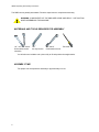
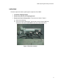
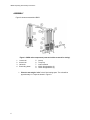
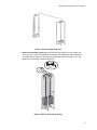
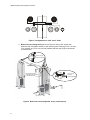
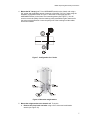
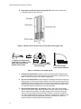
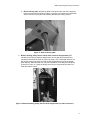
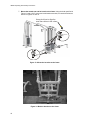
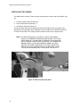
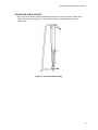
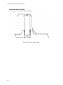
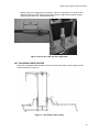
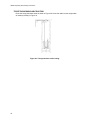
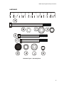
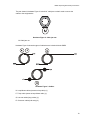
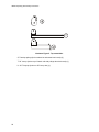
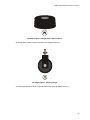
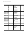
5 STACK MULTI-JUNGLE
WITH HIGH & LOW PULLEYS (SM50)
UNPACKING AND ASSEMBLY INSTRUCTIONS
M051-K50-B115
1
SM50 Unpacking & Assembly Instructions
The SM50 comes partially assembled. Follow the steps below to complete the assembly.
WARNING: COMPONENTS OF THE SM50 ARE LARGE AND HEAVY. USE CAUTION
WHEN ASSEMBLING THIS MACHINE.
MATERIALS AND TOOLS REQUIRED FOR ASSEMBLY
1/2”, 3/8”, 5/8” & 9/16”
Socket wrench with
extension
1/8”
hex key wrench
5/8” & 9/16”
Combination wrench
Pinch bar
You will also need a ladder and a piano dolly to lift and position the weight stacks.
ASSEMBLY TIME
Two people can accomplish this assembly in approximately 2 hours.
2
SM50 Unpacking & Assembly Instructions
UNPACKING
Follow the steps below when unpacking the components of the SM50.
1. Cut off the shipping wrapper.
2. Remove the parts box and shipping boards.
3. Remove the items in the parts box. These items are shown in Figure 1.
A. Remove the bolts bag.
B. Remove the parts shown below. Parts that are used to build the SM50 are
described in the section HARDWARE at the end of these instructions.
Figure 1. Parts box contents.
3
SM50 Unpacking & Assembly Instructions
ASSEMBLY
Figure 2 shows an assembled SM50.
Figure 2. SM50 main components (seats and cables removed for clarity).
1.
2.
3.
4.
1 stack cell
4 stack cell
Lat bench
Connecting beam
5.
6.
7.
8.
9.
Lat top
Tricep top
Low row bench
300 lb. Weight stacks (2)
190 lb. Weight stacks (3)
1. Place the two weight “cells” in their final resting spots. The cells will be
approximately 11’4” apart as shown in Figure 3.
4
SM50 Unpacking & Assembly Instructions
Figure 3. Set the weight stack cells.
2. Bolt on the teardrop pulleys above the benches (see Figure 4) on the 4 stack cell
using two 3/8” x 2-3/4” hex head bolts. Include the 3/8” flat washer, end cap washers,
end caps and 3/8” Nyloc nut. Use the bolt configuration shown in Figure 5. You may
wish to use a pinch bar to align the bolt holes.
3/8” x 2-3/4” (6)
Figure 4. Bolt on the teardrop pulleys.
5
SM50 Unpacking & Assembly Instructions
Figure 5. Configuration for 2-3/4” and 3” bolts.
3. Bolt on the connecting beam (part 4 from Figure 2) using a 5/8” socket with
extension and combination wrench, to the cells using two of the large 7/16” x 6” bolts,
7/16” washers, and 7/16” nuts, end cap washers and end caps. Figure 6 shows the
connected cells.
7/16” x 6” (6)mount on tops
Remove pulleys from
housings to give clearance
to socket extension
Figure 6. Bolt on the connecting beam, lat top, and tricep top.
6
3/8” x 3” (2)bolt top
beams together
SM50 Unpacking & Assembly Instructions
4. Mount the 56” lat top (part T from HARDWARE section) to the 4-stack cell using a
5/8” socket and combination wrench. Insert two of the large 7/16” by 6” bolts using the
hardware configuration shown in Figure 7. Mount the 29” tricep top (part U in
HARDWARE section) to the frame and connecting beam (See Figure 7). You will
need to remove the pulleys from the teardrop pulley assemblies to gain clearance for
the socket wrench extension. Leave the pulleys out of the housings until the cables
have been installed.
Figure 7. Configuration for 6” bolts.
Figure 9. Mount the weight stacks.
5. Mount the weight stacks to the 4-stack cell. To do this:
A. Remove the tricep back rest bolts using a 9/16” socket and combination
wrench (see Figure 10).
7
SM50 Unpacking & Assembly Instructions
B. Unbolt the top plate and remove the guide rods using a 9/16” socket and
combination wrench (see Figure 10).
Figure 10. Remove the tricep back rest, the top plate and the guide rods.
C. Prepare the weight stackadd bumpers to bottom, insert
guide rods, put pull pin in
bottom plate of stack.
D. Flip over the weight stack
onto piano dolly.
E. Hoist the weight
stack onto the machine.
Figure 11. Putting on the weight stacks.
C. Prepare the weight stacks. Slide the guide rods (2) through the weight stacks
(1) as shown above. Place rubber bumpers (3) on the bottoms of each guide rod.
Make sure the pull pin (4) is in the bottom weight plate.
D. Flip over the weight stacks. When shipped, the weight stacks have the pull pins
facing upward. You will need to flip the stacks over so that the pull pins are facing
outward when they are loaded onto the machine. Since the pull pins will be facing
downward when they are flipped over, it is recommended that you put the stacks
on a padded carpet to keep the pins from being damaged.
E. Set the weight stacks onto the machine. Using a piano dolly, lift the weight
stacks over the bottom plate and set the stacks onto the rubber bumpers with the
plate numbers facing outward. The 300 lb weight stacks need to be facing the
“sides” of the cells (where the benches will be attached- number 8 in Figure 9).
The 190 lb weight stacks will need to be facing the “outsides” and “insides” of the
cells (where the tricep pulley adjustable pulleys will be attached- number 9 in
Figure 9). Make sure all pull pins are facing outward.
8
SM50 Unpacking & Assembly Instructions
F. Bolt on the top plate. With the top plate on the guide rods, bolt on the top plate
to the top of the cells as shown in Figure 11 using a 9/16” socket and combination
wrench and the 3” bolts (with cap washers) that were previously inserted.
Figure 11. Bolt on the top plate.
6. Bolt the floating pulley into the 190 lb cable crossover weight stack (NOT
intended for the tricep pushdown weight stack- the one with the tricep back rest
mounted to the frame as shown in Figure 10) using a 7/8” combination wrench. You
will need to remove the pulley from the housing to thread the plug into the weight
stack bayonet. Make sure the 9/16” jam nut is threaded 1-5/8” away from the pulley
as shown in Figure 12. Leave the pulleys out since you will need to have them out
when the cable is routed.
Figure 12. Bolt the floating pulley into the 190 lb weight stack (on cable crossover).
9
SM50 Unpacking & Assembly Instructions
7. Mount the seated row and lat bench to the frame. Using the bolts specified in
Figure 12 and a 9/16” socket and combination wrenches, mount the benches as
shown in Figures 13 and 14.
Use a pinch bar to align the
seat frame holes to the cubes
3/8 x 2-3/4”
(8)
3/8 x 3”
(2)
Figure 13. Mount the benches to the frame.
Figure 14. Bolt the benches to the frame.
10
SM50 Unpacking & Assembly Instructions
11
SM50 Unpacking & Assembly Instructions
INSTALLING THE CABLES
The SM50 uses five cables. There are three different types of cable used on the SM50. They
are:
1. Crossover cables (ball end cables) (2).
2. Low row cable (the long cables) (1).
3. Lat pulldown and tricep cables (2).
The lat and tricep cables can be identified by their short length, the low row cable can be
identified by its long length and the adjustable crossover cables can be identified by the ball
on the end of the cable. The routings for these cables are shown in the figures below.
NOTE: YOU MUST REMOVE ALL PULLEYS TO ROUTE THE CABLES.
USE A 9/16” COMBINATION WRENCH AND SOCKET TO DO THIS
(SEE FIGURE 16). YOU MAY WISH TO REMOVE THE SHOULDER
BOLTS (FIGURE 16 RIGHT SIDE) BY USING A 3/8” COMBINATION
WRENCH AND A 1/8” HEX KEY WRENCH. WHEN YOU HAVE
ROUTED THE CABLES, REPLACE ALL PULLEYS AND PLACE
END CAPS ON NUT AND BOLT ENDS. YOU MAY NEED TO PRY
THE PULLEY HOUSINGS OPEN TO REPLACE THE PULLEYS.
Figure 15. Removing the pulley bolts.
12
SM50 Unpacking & Assembly Instructions
CROSSOVER CABLE ROUTING
Once you’ve removed the pulleys as described previously, route the crossover cables on the
4-stack cell as shown in Figure 16. The crossover cable is routed at the factory on the
1-stack cube.
Figure 16. Crossover cable routing.
13
SM50 Unpacking & Assembly Instructions
LOW ROW CABLE ROUTING
Route the low row cable as shown in Figure 17.
Figure 17. Low row cable routing.
14
SM50 Unpacking & Assembly Instructions
Bolt the cable to the weight stacks as shown in Figure 18. Thread the 7/8” nut up on the
cable bolt as shown at left. Screw the bolt down into the weight stack as shown at right.
Tighten the bolt with a 7/8” combination wrench.
Figure 18. Screw the cable into the weight stack.
LAT PULLDOWN CABLE ROUTING
Route the lat pulldown cable as shown in Figure 19. Screw the cable into the weight stack as
shown previously in Figure 18.
Figure 19. Lat pulldown cable routing.
15
SM50 Unpacking & Assembly Instructions
TRICEP PUSHDOWN CABLE ROUTING
Route the tricep pushdown cable as shown in Figure 20. Screw the cable into the weight stack
as shown previously in Figure 18.
Figure 20. Tricep pushdown cable routing.
16
SM50 Unpacking & Assembly Instructions
HARDWARE
½
0
½
1
½
2
½
3
½
4
½
5
6
Hardware Figure 1. Assembly Parts.
17
SM50 Unpacking & Assembly Instructions
The parts shown in Hardware Figure 1 are used to assemble the SM50. They are:
A. 7/16” x 6” hex head bolt (used to bolt the tricep top beam, adjustable crossover top
beam, lat top beam, and connecting beam to the tops of the cells)
B. 7/16” flat washer
C. 7/16” cap washer (used on the head end of the 6” bolt so end cap will fit on the nut)
D. 7/16” hex head nut
E. 3/8” x 3” hex head bolt (used to bolt the cross beam to the cross members, the
adjustable pulley tops to the top beams, and the bottom bolts on the lat bench)
F. 3/8” x 2-3/4” hex head bolt (used for all other connections)
G. End caps (bolt covers)
H. 3/8” flat washer
J.
3/8” end cap washers (end caps snap onto them)
K. 3/8” Nyloc (locknut)
18
SM50 Unpacking & Assembly Instructions
The part shown in Hardware Figure 2 is the 9/16” cable jam nut that’s used to secure the
cables to the weight stacks.
Hardware Figure 2. Cable jam nut.
M. Cable jam nut
Hardware Figure 3 shows the types of cables that are included with the SM50.
Hardware Figure 3. Cables.
N. Lat pulldown cables (same as tricep cable) (1)
P. Tricep cable (same as lat pulldown cable) (1)
Q. Low row cables (long cables) (1)
R. Crossover cables (ball ends) (2)
19
SM50 Unpacking & Assembly Instructions
Hardware Figure 5. Top assemblies.
S. Teardrop pulleys (bolt on above lat and seated row bench) (2)
T. 56” Lat top (bolt to top of 4-stack cell with pulleys above lat bench) (1)
U. 29” Tricep top (bolt on to 56” lat top bar) (1)
20
SM50 Unpacking & Assembly Instructions
Hardware Figure 6. Weight stack rubber bumpers.
W. Weight stack rubber bumpers (inserted under weight stacks) (8)
Hardware Figure 7. Floating pulleys.
X. Floating pulley (bolt to 190 lb weight stack other than tricep pushdown stack) (1)
21
SM50 Unpacking & Assembly Instructions
PARTS LIST
Part #
ID
Description
Quantity
Main components
1
2
3
4
5
6
7
8
9
1-stack cell
4-stack cell
Low row bench
Connecting beam
Lat top
Tricep top
Lat bench
300 lb weight stack
190 lb weight stack
1
1
1
1
1
1
1
2
3
0017-00103-0234
0017-00101-1408
0017-00101-1408
0017-00101-1422
0017-00101-1561
Cables, caps & nuts
M
N
P
Q
R
Cable jam nut
Lat pulldown cable
Tricep cable
Low row cable
Crossover cable
5
1
1
1
2
0017-00101-1561
0017-00104-0363
0017-00104-0366
0017-00103-0233
6” bolt hardware
A
B
C
D
7/16” x 6” hex head bolt
7/16” flat washer
7/16” cap washer
7/16” Nyloc nut
6
6
6
6
0017-00101-1422
0017-00101-1408
0017-00042-0969
0017-00104-0313
0017-00104-0368
0017-00103-0217
2-3/4” & 3”
bolt hardware
E
F
G
H
J
K
3/8” x 3” hex head bolt
3/8” x 2-3/4” hex head bolt
End cap
3/8” flat washer
3/8” end cap washer
3/8” Nyloc nut
4
12
32
32
32
16
Pulleys and bumpers
W
X
Weight stack rubber bumper
Floating pulley
8
1
Safety carabiner
Crossover handle
Tricep bar
Lat bar
Low row handle
Leg strap
5
2
1
1
1
1
0017-00042-0993
Handle and bar
hardware
22
SM50 Unpacking & Assembly Instructions
Pulley hardware
(installed)
0017-00101-1413
0017-00104-0368
0017-00103-0217
1-3/4” Bolt
Cap washer
3/8” Nyloc nut
Floating pulley
hardware (installed)
0017-00101-1413
0017-00104-0313
0017-00103-0217
1-3/4” Bolt
Flat washer
3/8” Nyloc nut
23