1
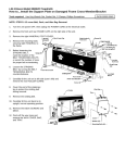
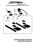
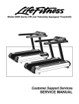
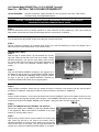
Life Fitness Model 9500HRT(Rev 1 & 2) & 9500HR Treadmill
How To... INSTALL THE LIFELINK UPGRADE KIT
TOOLS REQUIRED:
Standard Screwdriver, Phillips Screwdriver, Hex Key Wrench Set, Pliers, Wire Cutters,
Anti-Static Strap, Small Adjustable Wrench
WARNING: FAILURE TO OBSERVE SAFETY PROCEDURES WHEN SERVICING THIS UNIT
COULD RESULT IN INJURY FROM ELECTRICAL SHOCK
(9500HR ONLY)
STEP 1:
Enter into the service menu by pressing manual-9-1-9, enter. Press the fit test program key ( 0001 ) and record the
total number of times the wax pump has discharged while the unit has been in operation.
STEP 2:
Turn the power off at the ON/OFF switch and unplug the unit at the wall outlet.
STEP 3:
Ground yourself by positioning an anti-static strap around your wrist and attaching the other end (alligator clip or
adhesive end) to a bare metal surface on the machine frame.
(9500HRT REV 2 ONLY)
STEP 3:
With the help of another person, tip the treadmill onto its user
right side. Follow the left side of the frame to the middle. Using a
standard screwdriver, pop open the three plastic rivets securing
the control board shelf to the frame. Pull the shelf downward and
towards you to lower the CONTROL BOARD SHELF on its
hinges.
STEP 4:
Plug the NETWORK HARNESS supplied in the upgrade kit to
the additional plug connector on the CONTROL BOARD marked
P7. Route the NETWORK HARNESS along the frame towards
the front of the unit to the POWER MODULE. Replace the
CONTROL BOARD SHELF back into its original position.
(9500HRT REV 1 AND 9500HR ONLY)
STEP 4:
Using a Phillips screwdriver, remove the four screws securing the connector cover located under the user left side of
the DISPLAY CONSOLE. Unplug the 4-PIN and 10-PIN connectors to the DISPLAY CONSOLE.
STEP 5:
Using a Phillips screwdriver, remove the eight screws that hold the CONSOLE PAN to the faceplate. Remove the four
screws securing the Lifepulse assembly and unplug the 7-PIN CONNECTOR and the ground strap. Remove the eight
screws securing the ELECTRONIC BOARD to the faceplate. Unplug the ribbon and stop switch cables.
STEP 6:
NOTE THE ORIENTATION OF E-PROM BY THE U-NOTCH.
Remove and replace the E-PROM (U1) with the E-PROM supplied
in the upgrade kit. Return the DISPLAY CONSOLE to its proper
position by reversing Steps 4 and 5.
STEP 7:
With the help of another person, tip the treadmill onto its user right
side. Follow the left side of the frame to the middle. Using a
standard screwdriver, pop open the three plastic rivets securing the
control board shelf to the frame. Pull the shelf downward and
towards you to lower the CONTROL BOARD SHELF on its hinges
Life Fitness Model 9500HR & 9500HRT(Rev 1 & 2) Treadmill
How To... INSTALL THE LIFELINK UPGRADE KIT
STEP 8:
Disconnect the seven connectors to the CONTROL BOARD taking note of their positions. With a standard
screwdriver, remove the six screws securing the CONTROL BOARD to the shelf. Place the new CONTROL BOARD
supplied in the upgrade kit onto the shelf and replace the six screws.
STEP 9:
Using the 6-PIN adapter cable supplied in the upgrade kit, connect the POWER SUPPLY CABLE to location P2 on
the CONTROL BOARD. Using the 10-PIN adapter cable supplied in the upgrade kit, connect the DISPLAY CABLE to
location P3 on the CONTROL BOARD. Reconnect all other connectors to the CONTROL BOARD.
(9500 HR ONLY)
STEP 10:
Plug the unit in at the wall outlet and turn the power on at the ON/OFF switch. Enter the service menu by pressing
manual-8-2-2-8, enter.
STEP 11:
Select “NEW CPU” by pressing 2.
STEP 12:
Enter the number of waxings recorded in Step 1.
STEP 13:
Turn the power off at the ON/OFF switch and unplug the unit at the wall outlet. Plug the NETWORK HARNESS
supplied in the upgrade kit to the additional plug connector on the CONTROL BOARD marked P7. Route the
NETWORK HARNESS along the frame towards the front of the unit to the POWER MODULE. Replace the CONTROL
BOARD SHELF back into its original position.
STEP 14:
Using a hex key wrench, remove the user left FRONT END CAP. Loosen but
do not remove, the two screws on the front left side of the POWER MODULE
using a small adjustable wrench. Install the NETWORK BOARD ASSEMBLY
supplied in the upgrade kit (connector facing the floor) onto the two screws
previously loosened. Tighten the two screws to fasten the assembly in place.
Connect the NETWORK HARNESS installed earlier to the NETWORK BOARD
ASSEMBLY.
STEP 15:
Plug the STUB CABLE supplied in the upgrade kit to the NETWORK BOARD.
Plug the remaining end of the STUB CABLE into the t-connector on the
backbone. With cable ties, strain relief the STUB CABLE away from the incline
and roller mechanisms. Replace the FRONT END CAP. Tip the treadmill back
up to an upright position.
STEP 16:
Plug the unit in at the wall outlet and turn the power on at the ON/OFF switch.
A blue box will appear on the LIFECENTER SCREEN stating “INSTALLING
NODE” and will disappear in approximately 30 seconds.
NOTE: DO NOT TURN OFF THE POWER OR DISCONNECT THE NETWORK
DURING THIS TIME. DOING SO BEFORE
THE “INSTALLING NODE” MESSAGE DISAPPEARS
MAY DEACTIVATE THE NETWORK BOARD.
Should you require any assistance with this Technical Information, please direct all inquiries to:
Customer Support Services
10601 West Belmont Avenue
Franklin Park, IL 60131
(800) 351-3737 or (847) 451-0036 / FAX (847) 451-4137
MO51-00K23-A012