1
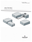
DISCONTINUED
PRODUCT
S
■
■
■
■
■
I T E
■
■
M
O N I T O R I N G
■
MR1
Mini-Remote
Environmental Monitor
USER MANUAL
DISCONTINUED
PRODUCT
TABLE OF CONTENTS
Section 1: INTRODUCTION.......................................................................................... 1
Specifications ................................................................................................................................................ 1
Section 2: INSTALLATION ........................................................................................... 3
Mounting........................................................................................................................................................ 3
Electrical Connections................................................................................................................................... 5
Section 3: HARDWARE CONFIGURATION ................................................................. 7
DIP Switch Settings ....................................................................................................................................... 7
Section 4: OPERATION................................................................................................ 9
LCD and Keypad ........................................................................................................................................... 9
Setpoint Control........................................................................................................................................... 10
TABLE OF FIGURES
Figure 1. Typical System Configuration ........................................................................................................ii
Figure 2a. Flush-Mount Installation .............................................................................................................. 4
Figure 2b. Display Panel Mounted Remotely from Electrical Box ................................................................ 6
Figure 3. Electrical Connections, Electric Box and Display.......................................................................... 8
Figure 4. LCD Display .................................................................................................................................. 9
Figure 5. Display Panel .............................................................................................................................. 10
DISCONTINUED
PRODUCT
Figure 1. Typical System Configuration
DISCONTINUED
PRODUCT
DISCONTINUED
PRODUCT
Section 1: INTRODUCTION
The Liebert MR1 Mini-Remote monitors the operating status
and controls the operation of your Liebert Environmental unit.
It serves as a remote user interface, supplementing the unit-front
controls.
The MR1 is compatible with all Liebert microprocessorcontrolled Environmental units, including:
• Deluxe System 3 and Challenger units with
• Advanced Microprocessor with Graphics
• Advanced Microprocessor
• Standard Microprocessor
• Level 10
• Level 00
• Mini-Mate2 ceiling-mounted units
• Mini-Mate, Mini-Mate Plus and Data-Mate units with
Small Systems Controllers.
An LCD display provides temperature, humidity, status and
alarm information. The MR1 provides both visual and audible
annunciation of alarms from the Environmental unit. Unmarked
“hidden” buttons allow the MR1 user to access setpoints and
settings.
Specifications
Electrical Specifications:
Voltage: 24 VAC, +/-10% of nominal
Power:
7.5 VA
Phase:
1
Frequency: 50/60 Hz
Environmental Conditions:
Operating Temperature:
5°C to 40°C
Operating Relative Humidity: 0% to 95% (non-condensing)
Operating Altitude:
up to 2000 meters
Dimensions:
Display Panel: 3 1/2”H x 5”W x 1 1/8”D
89mm x 127mm x 29mm
Electrical Box: 4
3/4”
H
x
4
121mm x 121mm x 70mm
0.5 lbs
0.23 kg
3/4”W
x
0.91 kg
Liebert MR1 • 1
DISCONTINUED
PRODUCT
2
3/4”D
NOTE
This equipment has been tested and found to
comply with the limits for a Class A digital
device, pursuant to part 15 of the FCC rules.
These limits are designed to provide reasonable
protection against harmful interference when the
equipment is operated in a commercial
environment. This equipment generates, uses,
and can radiate radio frequency energy and, if
not installed and used in accordance with the
instruction manual, may cause harmful
interference
to
radio
communications.
Operation of this equipment in a residential area
is likely to cause harmful interference in which
case the user will be required to correct the
interference at his own expense.
NOTE
When the following symbols are displayed, they
indicate:
a.
Earth grounding conductor
b.
Alternating Current
2 • User Manual
DISCONTINUED
PRODUCT
Section 2: INSTALLATION
Mounting
The MR1 Mini-Remote is completely tested, then shipped from
the factory disassembled for your convenience during
installation. To begin flush-mount installation, please refer to
Figure 2A. An optional 30-foot control cable can be supplied to
allow the display to be located remotely from the electrical box.
Refer to Figure 2b.
The electric box containing the power supply is designed for
flush-mounting into a finished interior wall. A wall plate is
supplied to cover the drywall opening, with the display mounted
directly in front of the wall plate/electric box.
1. Mount the electric box (Item 5) in the wall at a convenient
location.
NOTE: Use minimum
18 gauge wire for all
customer interface wiring.
2. Make each power and unit connection (to Item 4) by
inserting bare wire end into compression terminal and
tightening screw. Refer to Electrical Connections section.
If 30-foot cable is used, disconnect factory wire harness and
attach cable to screw terminals per Figure 2.
3. Route control cable through wall plate and electric box
cover, then connect to electrical box at TB1 (on Item 4).
4. Attach electric box cover (Item 3) with two (2) screws.
5. Remove the front cover from the MR1 display panel (Item
1) by gently prying open at the slots on the top and bottom
of the display. Attach the control panel rear plastic and the
wall plate (Item 2) to the electric box with two (2) screws.
6. Snap display panel front onto the rear plastic part.
7. Apply power to the MR1. Operate the system to test status
and alarm monitoring, and customer selected options
including on/off control. Also test optional customer
interface (4 inputs and 1 output), if applicable.
Call Liebert Environmental Support at 1-800-543-2778 if
assistance is required for the installation or operation of the
Mini-Remote.
Liebert MR1 • 3
DISCONTINUED
PRODUCT
Figure 2a. Flush-Mount Installation
4 • User Manual
DISCONTINUED
PRODUCT
Electrical Connections
Caution: Ensure Environmental
unit has sufficient 24VAC power
to support the MR1, Liqui-tects
or any other auxiliary device.
Liebert
Environmental
Controller
The MR1 Mini-Remote requires a two-wire connection (fieldsupplied) to communicate with the Environmental unit under its
control. The stranded twisted-pair connects to the MR1 interface
board at TB2-11 (T+) and TB2-12 (T-). Refer to Table 1 below
for the connections at the Environmental unit. Note that
maximum length for RS-422 communications is 1000 feet, and
minimum of 22 gauge wire should be used for all field wiring.
Power for the MR1 is supplied to TB3-1 and TB3-2. Maximum
current draw is 0.3A at 24VAC. It is recommended that the
MR1 be powered independently from an external 24VAC
transformer; optionally, it may draw power from the
Environmental unit. However, if the MR1 is located greater
than 300 feet (100 meters) from the Environmental unit, an
external transformer must be used.
24VAC
Auxiliary
Power
Connection to MR1
TB2-11 (T+)
TB2-12 (T-)
Terminal T5
Terminal G5
Terminal 78 (T+)
Terminal 77 (T-)
TB1-1
TB1-5
Terminal 78 (T+)
Terminal 77 (T-)
Mini-Mate 2
-
TB4-1 (T+)
TB4-2 (T-)
SSC - Small System
Controller
-
TB2-1 (T+)
TB2-2 (T-)
SM - Standard
AM/AG - Advanced
L10 - Level 10
Microprocessors
L00 - Level 00
Microprocessor
Table 1: Connection Summary
The MR1 provides a Common Alarm Output, at TB2-9 and
TB2-10. This dry-contact is rated for 5A, at 24VDC or
120VAC.
NOTE: New Feature. The inputs
are now contact-closure –
24VAC powered inputs are no
longer necessary.
NOTE: Exercise caution if
installing new MR1 as
replacement unit: remove power
from signal inputs, or damage to
unit may occur!
There are four optional Customer Alarm inputs that may be used
on the MR1 (see Hardware Configuration). The inputs are
triggered by contact-closures, and the contacts are rated for 5A,
at 24VDC or 120VAC as well. The connection points and
display mapping are as follows:
Local Alarm 1:
Local Alarm 2:
High Water Alarm:
High Head Alarm:
TB2-3
TB2-1
TB2-5
TB2-7
&
&
&
&
TB2-4
TB2-2
TB2-6
TB2-8
Liebert MR1 • 5
DISCONTINUED
PRODUCT
Figure 2b. Display Panel Mounted Remotely from Electrical Box
6 • User Manual
DISCONTINUED
PRODUCT
Section 3: HARDWARE CONFIGURATION
DIP Switch Settings
The following user selectable operations are set by DIP SW1 on
the display panel circuit board: Refer to Table 2 and Figure 3.
Position
1
2
3
4
OFF
Audible beeper
enabled
Remote on/off
disabled. On/off
button affects MR1
operation only
Optional alarm inputs
disabled
Common alarm
follows alarm
condition
ON
Audible beeper
disabled
Remote on/off of
Env. unit enabled.
Env. unit must have
remote on/off
capability, or MR1
will not be able to
perform this function
4 optional alarm
inputs enabled
Common alarm
de-energized when
alarm is silenced
Table 2: DIP Switch Settings
Note that factory default is OFF for all four positions.
Liebert MR1 • 7
DISCONTINUED
PRODUCT
Figure 3. Electrical Connections, Electric Box and Display
8 • User Manual
DISCONTINUED
PRODUCT
Section 4: OPERATION
LCD and Keypad
When power is first applied, the MR1 performs selfinitialization and then enters the normal display mode. The
display alternates between showing the temperature and
humidity readings, and cooling/heating, de/humidification, and
econocycle operating status.
Pressing the HOLD button will lock on the temperature or
humidity reading, continuously updating it two times per second.
It will continue to display the same parameter until the SCAN
button is pressed or a new alarm occurs.
Figure 4. LCD Display
When you press the SCAN button, the MR1 first scans through
the active alarms if any exist, then scans through the heating,
cooling, de/humidification, and econocycle/capacity. On chilled
water/hot water units, percent capacity indicates the valve
position. On units equipped with econocycle, cooling will
reflect the valve position. If econocycle is not available,
econocycle capacity status is skipped.
While scanning, the HOLD button can be pressed to lock the
display on the current item for continuous updating. To return
to scanning, press the SCAN button again. After all parameters
have been displayed, the monitor returns to the normal
alternating status display.
Should a new alarm occur while scanning (or at any other time),
the MR1 immediately displays the alarm and annunciates it if
the beeper is enabled. The alarm can be silenced by pressing the
SILENCE button. On Small Systems Controls, silencing an
alarm at the MR1 will also silence the alarm at the unit; on other
microprocessors, an alarm that is no longer active can be reset
from the MR1 by pressing the SILENCE button.
OFF is displayed when the MR1 has been turned off; OFF
flashes if communication between the MR1 and the
Environmental unit is disrupted.
With DIP switch #2 in the ON position and monitoring a unit
equipped with remote on/off capability, pressing the ON/OFF
Liebert MR1 • 9
DISCONTINUED
PRODUCT
button will turn on/off the unit being monitored and the MR1.
With DIP switch #2 in the OFF position, pressing the ON/OFF
button will turn toggle the on/off operation of the MR1 only.
Setpoint Control
There are two hidden buttons on the MR1 keypad. These
buttons are not labeled on the display to prevent untrained
personnel from accessing unit settings.
Figure 5. Display Panel
The F/C button will toggle between degrees Fahrenheit and
degrees Celsius for the temperature display.
The SET button will put the MR1 in the set mode. The SET
icon in the upper left of the LCD will be displayed along with
other icons to indicate which setpoint is being viewed or
changed. Use the /SCAN and the /HOLD buttons to change
the setpoint. The display will change with each key press to
indicate the new value of the setpoint. If the value does not
change, then the environmental unit is not accepting the new
value because it is out of range. The displayed value is always
the actual setpoint in the environmental unit. There are 8
setpoints that can be changed. The SET button is pressed to
advance to the next setpoint. After all 8 setpoints have been
stepped through, the MR1 will go back to the normal display
mode. The SILENCE button can be pressed at any time to exit
the set mode.
The 8 setpoints are:
1.
2.
3.
4.
Temperature Setpoint
Temperature Sensitivity
Humidity Setpoint
Humidity Sensitivity
5. High Temp Alarm
6. Low Temp Alarm
7. High Hum Alarm
8. Low Hum Alarm
Note that the temperature sensitivity is in tenths but there is no
decimal point on the MR1 display so, for example 1.4 is
displayed as 14.
Refer to Table 3 for availability by microprocessor of setpoint
control:
10 • User Manual
DISCONTINUED
PRODUCT
Setpoint
On/Off
Temperature
Temp Sensitivity
Humidity
Humidity Sensitivity
High Temperature Alarm
Low Temperature Alarm
High Humidity Alarm
Low Humidity Alarm
AM/AG
✔
✔
✔
✔
✔
✔
✔
✔
✔
SM
**
✔
✔
✔
✔
L10
✔
✔
✔
✔
✔
✔
✔
✔
✔
L00
**
✔
✔
✔
✔
MM2
✔
✔
✔
✔
✔
✔
✔
✔
✔
SSC
✔
Table 3: Setpoint Control by Microprocessor
** Modification to the K3 common alarm relay on the
microprocessor controls of the Environmental unit is necessary
to enable remote on/off – this modification will necessarily
eliminate the common alarm relay output. Refer to the
Installation / Operations Manual of the Environmental unit, or
consult Liebert Environmental Support.
Note that if the high/low temperature and humidity alarm
setpoints are disabled at the unit controls, then the MR1 will
display 00 for the setpoint. The MR1 is not able to remotely
enable alarm setpoints.
The MR1 will annunciate any alarm transmitted by the
Environmental controls. Table 4 catalogs the available alarms
by microprocessor level.
Liebert MR1 • 11
DISCONTINUED
PRODUCT
Alarm
High Temperature
Low Temperature
High Humidity
Low Humidity
High Head Pressure 1
High Head Pressure 2
Loss of Airflow
Liquid Detected
Change Filters
Humidifier Problem
No Water in Hum’fier Pan
Standby Glycool Unit On
Compressor 1 Overload
Compressor 2 Overload
Main Fan Overload
Manual Override
Smoke Detected
Loss of Water
Standby Unit On
Low Suction
Short Cycle
Loss of Power
Inverter Bypass
Standby Fan On
Loss of Emergency Power
Local Alarm [1]
Local Alarm 2
AM/AG
✔
✔
✔
✔
✔
✔
✔
✔
✔
✔
✔
✔
✔
✔
✔
✔
✔
✔
✔
✔
✔
✔
✔
✔
✔
✔
✔
SM
✔
✔
✔
✔
✔
✔
✔
✔
✔
✔
L10
✔
✔
✔
✔
✔
✔
✔
✔
✔
✔
✔
✔
✔
✔
✔
✔
✔
✔
✔
✔
✔
✔
✔
✔
✔
✔
✔
L00
✔
✔
✔
✔
✔
✔
✔
✔
✔
✔
MM2
✔
✔
✔
✔
✔
✔
✔
✔
✔
✔
✔
✔
✔
✔
✔
✔
✔
✔
✔
✔
✔
✔
✔
✔
✔
✔
✔
SSC
✔
✔
✔
✔
Table 4: Alarms by Microprocessor
12 • User Manual
DISCONTINUED
PRODUCT
DISCONTINUED
PRODUCT
■
■
■
■
■
■
■
■
MR1
Mini-Remote
Environmental Monitor
With more than 500,000 installations around the globe, Liebert
is the world leader in computer protection systems. Since its
founding in 1965, Liebert has developed a complete range of
support and protection systems for sensitive electronics:
•
Environmental systems: close-control air conditioning
from 1.5 to 60 tons.
•
Power conditioning and UPS with power ranges from 250
VA to more than 1000 kVA.
•
Integrated systems that provide both environmental and
power protection in a single, flexible package.
•
Monitoring and control – on-site or remote – from systems
of any size or location.
•
Service and support, through more than 100 service
centers around the world, and a 24-hour Customer
Response Center.
LIEBERT CORPORATION
1050 DEARBORN DRIVE
P.O. BOX 29186
COLUMBUS, OHIO 43229
800.877.9222 PHONE
614.841.6022 FAX
LIEBERT EUROPE
LIEBERT ASIA
GLOBE PARK
MARLOW
BUCKINGHAMSHIRE SL7 1YG
UNITED KINGDOM
+44.1628.403200 PHONE
+44.1628.403203 FAX
19/F, CAUSEWAY BAY PLAZA
489 HENNESSY ROAD
CAUSEWAY BAY
HONG KONG
852.2.572.2201 PHONE
852.2.831.0114 FAX
LIEBERT W EB SITE
http://www.liebert.com
While every precaution has been taken to ensure accuracy and
completeness in this literature, Liebert Corporation assumes no
responsibility, and disclaims all liability for damages resulting from use of
this information or for any errors or omissions.
© 1996 Liebert Corporation. All rights reserved throughout the world.
Specifications subject to change without notice.
All names referred to are trademarks or registered trademarks of their
respective owners.
SL-31017 (Rev1, 8/99)
Printed in U.S.A.
DISCONTINUED
PRODUCT
THE COMPANY BEHIND
THE PRODUCTS