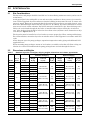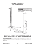
1
Precision Cooling
For Business-Critical Continuity™
Liebert® Air-Cooled, Direct-Drive Drycoolers
User Manual - 50/60Hz
DATA CENTER SOLUTIONS
For More Information:
(866) 787-3271
[email protected]
Figure i
Product model nomenclature
Example: DDNT350A48
D
D
N
Drycooler
Optional Disconnect
Switch on Models with No
Pump Control
T
350
C = No Fan Control
L = Main Fan Control
T = Fan Cycling
O = Fan Cycling and Pump
Control
S = Special Order Fan/Pump
Control
F = Fan Speed Control
N = No Pump Control
S = Single Pump Control
D= Dual Pump Control
A
48
P = 208/230V-1ph-60Hz *
W = 200/220V-1ph-50Hz
Y = 208/230V-3ph-60Hz
A = 460V-3ph-60Hz
B = 575V-3ph-60Hz
N = 200/230V-3ph-50Hz
M = 380/415V-3ph-50Hz
Model Size
48 = Optional Circuiting
(Blank for Standard
Circuiting) **
* Single-phase input voltage available only on DSF and DDF drycoolers and will require single-phase
pumps. For single-phase voltage on other drycoolers, consult factory for SFA DC2022 availability.
** See Tables 3 and 4 for standard and optional circuits available
TABLE OF CONTENTS
1.0
INTRODUCTION . . . . . . . . . . . . . . . . . . . . . . . . . . . . . . . . . . . . . . . . . . . . . . . . . . . . . . . . . .1
1.1
1.2
Product Description and Features. . . . . . . . . . . . . . . . . . . . . . . . . . . . . . . . . . . . . . . . . . . . . . . 1
Drycooler Control Options . . . . . . . . . . . . . . . . . . . . . . . . . . . . . . . . . . . . . . . . . . . . . . . . . . . . . 1
1.2.1
1.2.2
1.2.3
1.2.4
1.2.5
Fan Speed—DSF, DDF. . . . . . . . . . . . . . . . . . . . . . . . . . . . . . . . . . . . . . . . . . . . . . . . . . . . . . . . .
Fan Cycling Control—(D)DNT, DSO, DDO . . . . . . . . . . . . . . . . . . . . . . . . . . . . . . . . . . . . . . . .
Main Fan Control—(D)DNL . . . . . . . . . . . . . . . . . . . . . . . . . . . . . . . . . . . . . . . . . . . . . . . . . . . .
No Controls - (D)DNC. . . . . . . . . . . . . . . . . . . . . . . . . . . . . . . . . . . . . . . . . . . . . . . . . . . . . . . . . .
Pump Controls . . . . . . . . . . . . . . . . . . . . . . . . . . . . . . . . . . . . . . . . . . . . . . . . . . . . . . . . . . . . . . .
1
1
1
2
2
1.3
Typical System Configurations . . . . . . . . . . . . . . . . . . . . . . . . . . . . . . . . . . . . . . . . . . . . . . . . . 2
2.0
SITE PREPARATION . . . . . . . . . . . . . . . . . . . . . . . . . . . . . . . . . . . . . . . . . . . . . . . . . . . . . .6
2.1
2.2
Site Considerations . . . . . . . . . . . . . . . . . . . . . . . . . . . . . . . . . . . . . . . . . . . . . . . . . . . . . . . . . . 6
Dimensions and Weights . . . . . . . . . . . . . . . . . . . . . . . . . . . . . . . . . . . . . . . . . . . . . . . . . . . . . . 6
3.0
INSTALLATION . . . . . . . . . . . . . . . . . . . . . . . . . . . . . . . . . . . . . . . . . . . . . . . . . . . . . . . . . 14
3.1
Equipment Inspection . . . . . . . . . . . . . . . . . . . . . . . . . . . . . . . . . . . . . . . . . . . . . . . . . . . . . . . 14
3.2
3.3
3.4
Handling Unit on the Skid. . . . . . . . . . . . . . . . . . . . . . . . . . . . . . . . . . . . . . . . . . . . . . . . . . . . 15
Unpacking the Drycooler—All Sizes . . . . . . . . . . . . . . . . . . . . . . . . . . . . . . . . . . . . . . . . . . . . 16
Preparing a Drycooler for Moving and Installation—Units with One to Four Fans . . . . . . 17
3.1.1
3.4.1
3.5
Piping Guidelines . . . . . . . . . . . . . . . . . . . . . . . . . . . . . . . . . . . . . . . . . . . . . . . . . . . . . . . . . . . . 20
Expansion Tanks, Fluid Relief Valves, Air Management and Other Devices . . . . . . . . . . . . 21
Electrical Supply Preparation . . . . . . . . . . . . . . . . . . . . . . . . . . . . . . . . . . . . . . . . . . . . . . . . . 23
3.8.1
3.8.2
3.9
3.10
Attaching Legs, Removing the Skid and Attaching Slings—Units with Six or Eight
Fans . . . . . . . . . . . . . . . . . . . . . . . . . . . . . . . . . . . . . . . . . . . . . . . . . . . . . . . . . . . . . . . . . . . . . . . 18
Mounting the Drycooler . . . . . . . . . . . . . . . . . . . . . . . . . . . . . . . . . . . . . . . . . . . . . . . . . . . . . . 20
Glycol Piping Connections . . . . . . . . . . . . . . . . . . . . . . . . . . . . . . . . . . . . . . . . . . . . . . . . . . . . 20
3.7.1
3.7.2
3.8
Attaching Legs, Removing the Skid and Attaching Slings—Units with One to Four
Fans . . . . . . . . . . . . . . . . . . . . . . . . . . . . . . . . . . . . . . . . . . . . . . . . . . . . . . . . . . . . . . . . . . . . . . . 17
Preparing a Drycooler for Moving and Installation—Units with Six or Eight Fans . . . . . . 18
3.5.1
3.6
3.7
Packing Material . . . . . . . . . . . . . . . . . . . . . . . . . . . . . . . . . . . . . . . . . . . . . . . . . . . . . . . . . . . . 14
Line Voltage Wiring . . . . . . . . . . . . . . . . . . . . . . . . . . . . . . . . . . . . . . . . . . . . . . . . . . . . . . . . . . 23
Low Voltage Control Wiring . . . . . . . . . . . . . . . . . . . . . . . . . . . . . . . . . . . . . . . . . . . . . . . . . . . 27
High-Voltage Electrical Connections. . . . . . . . . . . . . . . . . . . . . . . . . . . . . . . . . . . . . . . . . . . . 29
Filling Instructions. . . . . . . . . . . . . . . . . . . . . . . . . . . . . . . . . . . . . . . . . . . . . . . . . . . . . . . . . . 32
3.10.1 Preparing the System for Filling . . . . . . . . . . . . . . . . . . . . . . . . . . . . . . . . . . . . . . . . . . . . . . . . 32
3.10.2 Glycol Solutions . . . . . . . . . . . . . . . . . . . . . . . . . . . . . . . . . . . . . . . . . . . . . . . . . . . . . . . . . . . . . 32
3.10.3 Filling the System . . . . . . . . . . . . . . . . . . . . . . . . . . . . . . . . . . . . . . . . . . . . . . . . . . . . . . . . . . . 33
4.0
CHECKLIST FOR COMPLETED INSTALLATION . . . . . . . . . . . . . . . . . . . . . . . . . . . . . . . . . . . 34
4.1
4.2
4.3
4.4
Moving and Placing Equipment . . . . . . . . . . . . . . . . . . . . . . . . . . . . . . . . . . . . . . . . . . . . . . .
Electrical . . . . . . . . . . . . . . . . . . . . . . . . . . . . . . . . . . . . . . . . . . . . . . . . . . . . . . . . . . . . . . . . . .
Piping . . . . . . . . . . . . . . . . . . . . . . . . . . . . . . . . . . . . . . . . . . . . . . . . . . . . . . . . . . . . . . . . . . . .
Other . . . . . . . . . . . . . . . . . . . . . . . . . . . . . . . . . . . . . . . . . . . . . . . . . . . . . . . . . . . . . . . . . . . . .
5.0
OPERATION . . . . . . . . . . . . . . . . . . . . . . . . . . . . . . . . . . . . . . . . . . . . . . . . . . . . . . . . . . .35
5.1
5.2
Startup Checklist . . . . . . . . . . . . . . . . . . . . . . . . . . . . . . . . . . . . . . . . . . . . . . . . . . . . . . . . . . . 35
Startup . . . . . . . . . . . . . . . . . . . . . . . . . . . . . . . . . . . . . . . . . . . . . . . . . . . . . . . . . . . . . . . . . . . 35
5.2.1
34
34
34
34
Drycooler Aquastat Setpoints . . . . . . . . . . . . . . . . . . . . . . . . . . . . . . . . . . . . . . . . . . . . . . . . . . 35
i
6.0
SYSTEM MAINTENANCE . . . . . . . . . . . . . . . . . . . . . . . . . . . . . . . . . . . . . . . . . . . . . . . . . . 37
6.1
General Procedures . . . . . . . . . . . . . . . . . . . . . . . . . . . . . . . . . . . . . . . . . . . . . . . . . . . . . . . . . 37
6.1.1
6.1.2
7.0
Drycooler Coil Cleaning . . . . . . . . . . . . . . . . . . . . . . . . . . . . . . . . . . . . . . . . . . . . . . . . . . . . . . . 37
Maintenance Inspection Checklist . . . . . . . . . . . . . . . . . . . . . . . . . . . . . . . . . . . . . . . . . . . . . . 39
TROUBLESHOOTING . . . . . . . . . . . . . . . . . . . . . . . . . . . . . . . . . . . . . . . . . . . . . . . . . . . . . 40
FIGURES
Figure i
Figure 1
Figure 2
Figure 3
Figure 4
Figure 5
Figure 6
Figure 7
Figure 8
Figure 9
Figure 10
Figure 11
Figure 12
Figure 13
Figure 14
Figure 15
Figure 16
Figure 17
Figure 18
Figure 19
Figure 20
Figure 21
Figure 22
Product model nomenclature . . . . . . . . . . . . . . . . . . . . . . . . . . . . . . . . . . . . . . . . . Inside Front Cover
Liebert three-fan drycooler. . . . . . . . . . . . . . . . . . . . . . . . . . . . . . . . . . . . . . . . . . . . . . . . . . . . . . . . . 1
Piping diagram, Liebert DS glycol semi-hermetic compressor models . . . . . . . . . . . . . . . . . . . . . . 3
Piping diagram, Liebert DS with GLYCOOL with digital scroll compressors . . . . . . . . . . . . . . . . 4
Typical piping arrangement, multiple drycoolers and multiple indoor units . . . . . . . . . . . . . . . . . 5
Drycooler planning dimensional data—One- and two-fan units . . . . . . . . . . . . . . . . . . . . . . . . . . . 8
Drycooler planning dimensional data—Three- and four-fan units . . . . . . . . . . . . . . . . . . . . . . . . . 9
Drycooler planning dimensional data—Six- and eight-fan units . . . . . . . . . . . . . . . . . . . . . . . . . . 10
Typical drycooler footprint—dimensions . . . . . . . . . . . . . . . . . . . . . . . . . . . . . . . . . . . . . . . . . . . . . 11
Piping connection locations for 1-, 2-, 3- and 4-fan drycoolers . . . . . . . . . . . . . . . . . . . . . . . . . . . . 11
Piping connections for 6- and 8-fan drycoolers . . . . . . . . . . . . . . . . . . . . . . . . . . . . . . . . . . . . . . . . 11
Equipment recommended for handling a Liebert drycooler . . . . . . . . . . . . . . . . . . . . . . . . . . . . . . 14
Forklift position with one-fan to eight-fan drycoolers . . . . . . . . . . . . . . . . . . . . . . . . . . . . . . . . . . 15
Lifting drycooler off skid. . . . . . . . . . . . . . . . . . . . . . . . . . . . . . . . . . . . . . . . . . . . . . . . . . . . . . . . . . 15
Removing protective material . . . . . . . . . . . . . . . . . . . . . . . . . . . . . . . . . . . . . . . . . . . . . . . . . . . . . 16
Attaching legs to one-fan to four-fan drycoolers . . . . . . . . . . . . . . . . . . . . . . . . . . . . . . . . . . . . . . . 17
Securing slings to one-fan to four-fan drycoolers for lifting off skid . . . . . . . . . . . . . . . . . . . . . . . 17
Remove skid, set drycooler on ground or level surface . . . . . . . . . . . . . . . . . . . . . . . . . . . . . . . . . . 18
Attach legs to six- and eight-fan drycoolers, remove from skid . . . . . . . . . . . . . . . . . . . . . . . . . . . 19
Rigging six-fan or eight-fan drycooler for lifting into position . . . . . . . . . . . . . . . . . . . . . . . . . . . . 19
Typical piping arrangement, multiple drycoolers and multiple indoor units . . . . . . . . . . . . . . . . 22
Electrical field connections for drycoolers without integral pump controls. . . . . . . . . . . . . . . . . . 30
Electrical field connections for drycoolers with integral pump controls . . . . . . . . . . . . . . . . . . . . 31
TABLES
Table 1
Table 2
Table 3
Table 4
Table 5
Table 6
Table 7
Table 8
Table 9
Table 10
Table 11
Table 12
Table 13
Table 14
Table 15
Table 16
Standard drycooler net weights, shipping weights, dimensions and volume, approximate . . . . . . 6
Liebert Quiet-Line drycooler net weights, shipping weights, dimensions and volume,
approximate. . . . . . . . . . . . . . . . . . . . . . . . . . . . . . . . . . . . . . . . . . . . . . . . . . . . . . . . . . . . . . . . . . . . . 7
Standard drycooler piping connection sizes and internal volume . . . . . . . . . . . . . . . . . . . . . . . . . 12
Liebert Quiet-Line drycooler piping connection sizes and internal volume . . . . . . . . . . . . . . . . . 13
60Hz electrical values - Drycoolers without pump controls . . . . . . . . . . . . . . . . . . . . . . . . . . . . . . 24
50Hz electrical values - Drycoolers without pump controls . . . . . . . . . . . . . . . . . . . . . . . . . . . . . . 25
60Hz Electrical values—Standard drycoolers with integral pump controls . . . . . . . . . . . . . . . . . 26
60Hz pump FLA values . . . . . . . . . . . . . . . . . . . . . . . . . . . . . . . . . . . . . . . . . . . . . . . . . . . . . . . . . . 26
60 Hz Electrical values - Liebert Quiet-Line drycoolers with integral pump controls . . . . . . . . . 27
Minimum recommended control circuit wire size, AWG, 60 Hz models . . . . . . . . . . . . . . . . . . . . 28
Minimum recommended control circuit wire size, mm2, 50Hz models . . . . . . . . . . . . . . . . . . . . . 28
Glycol concentrations for freeze protection by ambient temperatures . . . . . . . . . . . . . . . . . . . . . 33
Volume in standard Type "L" copper piping . . . . . . . . . . . . . . . . . . . . . . . . . . . . . . . . . . . . . . . . . . 33
Water/glycol system conditions requiring optional settings for aquastats . . . . . . . . . . . . . . . . . . 36
Aquastat settings—2-,3- & 4-fan drycoolers . . . . . . . . . . . . . . . . . . . . . . . . . . . . . . . . . . . . . . . . . . 36
Aquastat settings—6- and 8-fan drycoolers. . . . . . . . . . . . . . . . . . . . . . . . . . . . . . . . . . . . . . . . . . . 36
ii
Introduction
1.0
INTRODUCTION
1.1
Product Description and Features
The Liebert drycooler is a low-profile, direct-drive propeller fan-type air cooled unit. Constructed with
an aluminum cabinet and a copper-tube aluminum fin coil, the unit is quiet and corrosion resistant.
All electrical connections and controls are enclosed in an integral NEMA 3R rated electrical panel section of the drycooler.
Figure 1
Liebert three-fan drycooler
1.2
Drycooler Control Options
1.2.1
Fan Speed—DSF, DDF
Available only on single-fan standard drycoolers with integral pump controls. Fan speed control provides an infinite number of speed variations on specially designed, single-phase, permanent split
capacitor motor, by monitoring leaving fluid temperature.
Fan speed control provides air delivery in direct proportion to heat rejection requirements of the system. The control is adjustable to maintain the temperature of the fluid leaving the drycooler. Either of
two temperature ranges can be field-selected: 30 to 60°F (-1 to 16°C) for GLYCOOL™ applications or
70 to 100°F (21 to 38°C) for glycol applications.
1.2.2
Fan Cycling Control—(D)DNT, DSO, DDO
Available on all sizes of standard sound and Quiet-Line drycoolers. A thermostatic control cycles the
fan on a single-fan drycooler in response to leaving fluid temperatures. Two or more thermostats are
employed on drycoolers with two or more fans to cycle fans or groups of fans in response to leaving
fluid temperatures. The thermostat setpoints are listed on the factory-supplied schematic. They typically range from 35 to 45°F (2 to 7°C) for GLYCOOL applications and 65 to 75°F (18 to 24°C) for glycol
applications.
1.2.3
Main Fan Control—(D)DNL
Available for drycoolers without pump controls. All fans run when an external contact closure completes internal 24VAC circuit.
1
Introduction
1.2.4
No Controls - (D)DNC
Available on all drycoolers without pump controls. All fans are activated at full speed when power is
applied to the drycooler.
1.2.5
Pump Controls
Available on all Fan Speed and Fan Cycling Control drycoolers. Controls for pump(s) up to 7.5hp are
built into the same integral electric panel as the drycooler fan controls. Pump fuses, overload heaters
and flow switch (dual pump control models) are included with the Liebert pump packages or must be
field-supplied for field-supplied pumps.
Dual pump option—Provides controls for primary and standby pump. The flow switch senses loss of
flow and switches to the standby pump for continuous system operation in the event of a pump failure. An internal switch allows manual selection of the lead/lag pump.
1.3
Typical System Configurations
The standard glycol-cooled precision air conditioning system includes these major components:
•
•
•
•
•
•
•
•
indoor air conditioning unit with heat exchangers (refrigerant/glycol)
glycol regulating valve
outdoor air cooled drycooler
glycol pump(s)
expansion/compression tank
pump controls
interconnection piping
unit interlock control wiring
Figures 2 and 3 show a single unit to drycooler loop arrangement. Figure 4 shows a typical configuration of multiple indoor units and multiple outdoor drycoolers using a dual pump package and on a
common piping loop.
Additional field-supplied components, such as valves, expansion tank, strainers and flow or pressure
switches are also shown in Figures 2, 3 and 4. These components are necessary and should be
included when designing a system with one indoor and one outdoor unit on a piping loop or a system
using multiple indoor and outdoor units on a common piping loop. Larger systems may also benefit
from an air separator (not shown). See 3.0 - Installation for further details on required components.
2
Introduction
Figure 2
Piping diagram, Liebert DS glycol semi-hermetic compressor models
Optional Dual Pump System Shown
Liebert
Heat Rejection
Drycooler
(Glycol)
Expansion
Tank**
Aquastat
Sensing
Bulb
Hose
Bib *
Glycol Pumps
Check Valves *
(on Dual Pump
Systems only)
Pressure
Port *
Gate Valves *
Shutoff Valve *
Air Vents
(typical) ***
Pressure Port *
Flow Switch
Supplied with Dual
Pump Systems
Flow-Regulating
Valve
Shutoff Valve *
Return
Supply
Liebert DS Unit
Return
(and associated piping)
Optional
3-Way
Regulating
Valve
Liquid
Cylinder
Unloader(s)
Service
Valve
Sensing
Bulb
Suction
Evaporator
Coil
External
Service Equalizer
Discharge Valve
Solenoid
Valve
Filter
Drier
Relief valve(s)
supplied with 50Hz
EU CE units rated
maximum 480 PSIG
(33 Bar).
Hose Bib *
Bypass Valve
Paradenser®
Condenser
Sight
Glass
Hose
Bib *
Shutoff Valve *
2-Way
Regulating
Valve
Compressor
Muffler
Expansion
Valve
Shutoff Valve *
Supply
Sensor
To Second
Refrigeration
Circuit
Factory Piping
Field Piping
Optional Factory Piping
Service/Schrader (Access) Connection No Valve Core
Service/Schrader (Access) Connection With Valve Core
Note: Schematic representation shown. This schematic does not imply
or define elevations and component location unless specifically noted.
Two refrigeration circuits provided. Single refrigeration circuit shown for clarity.
* Components are not supplied by
Liebert, but are recommended for
proper circuit operation and
maintenance.
**Field-installed at highest point
in the system on the suction side of
the pump(s).
***Locate at tops of all risers and any
intermediate system high points.
DPN000895
Rev. 2
3
Introduction
Figure 3
Piping diagram, Liebert DS with GLYCOOL with digital scroll compressors
LIEBERT
HEAT REJECTION
Optional Dual Pump System shown
EXPANSION
TANK**
GLYCOL
PUMPS
Check Valves*
(on Dual Pimp
Systems only)
Gate Valves*
Pressure
Port*
DRYCOOLER
(Glycol)
Aquastat
Sensing
Bulb
Hose
Bib*
Shut-Off Valve*
Air Vents
(typical)***
Pressure Port*
Flow Switch
Supplied with Dual
Pump Systems
Flow-Regulating
Valve*
Shut-Off Valve*
LIEBERT DS UNIT
(and associated piping)
ECON-O-COIL
Sensing Bulb
53-70kW Digital
Solenoid Valve
SUPPLY
RETURN
SUPPLY
Shut-Off Valve*
LIQUID
28-42kW Digital Solenoid Valve
RETURN
EVAPORATOR
COIL
3-Way
Chilled Glycol
Valve
Thermistor
Hose
Bib*
Shut-Off Valve*
Hose
Bib*
SUCTION
Service
Valve
Service
Check
Valve
Valve COMPRESSOR
3-Way
Motorized
Ball Valve
External
Equalizer
From
iCOM
Control
DISCHARGE
PARADENSER®
CONDENSER
Expansion Solenoid Sight
Filter Drier
Valve
Valve
Pressure
Glass
Relief valve(s) supplied Transducer
with 50 Hz EU CE units rated
maximum 480 PSIG (33 Bar).
To
iCOM
Control
TO SECOND
REFRIGERATION
CIRCUIT
NOTE: TWO REFRIGERATION CIRCUITS PROVIDED
SINGLE REFRIGERATION CIRCUIT SHOWN FOR CLARITY.
*
FACTORY PIPING
FIELD PIPING
SERVICE / SCHRADER (ACCESS) CONNECTION NO VALVE CORE
SERVICE / SCHRADER (ACCESS) CONNECTION WITH VALVE CORE
Components are not supplied by
Liebert but are recommended for
proper circuit operation and
maintenance
** Field installed at highest point in
system on return line to pumps
*** Locate at tops of all risers and
any intermediate system high points
NOTE: SCHEMATIC REPRESENTATION SHOWN. THIS SCHEMATIC DOES NOT IMPLY OR DEFINE ELEVATIONS AND
COMPONENT LOCATION, UNLESS SPECIFICALLY NOTED.
4
DPN001432
Rev. 0
Introduction
Figure 4
Typical piping arrangement, multiple drycoolers and multiple indoor units
Expansion Tank
______ Gal. (L)
HP
GPM (l/s)
ft.
____(kW) ____ Per Pump @ ____(kPa)
FS
PUMP PACKAGE
Drycooler No. 1 Model ______
GPM (l/s) ____ P: ___ ft (kPa)
Cooling Unit #
Model
GPM (l/s)
P ft (kPa):
Cooling Unit #
Model
GPM (l/s)
P ft (kPa):
See Note 3
Cooling Unit #
Model
GPM (l/s)
P ft (kPa):
Drycooler No. 2 Model ______
GPM (l/s) ____ P: ___ ft (kPa)
Cooling Unit #
Model
GPM (l/s)
P ft (kPa):
LEGEND
Gate Valve
Check Valve
Butterfly Valve
Relief Valve
Union
Ball or Flow Control Valve
FS
P:
Cooling Unit #
Model
GPM (l/s)
P ft (kPa):
Cooling Unit #
Model
GPM (l/s)
P ft (kPa):
Flow Switch
Pressure Drop
Total
GPM
(L/s): _____
Pipe
Diam.: _____ In. (mm)
P: _____ Ft. (kPa)
Cooling Unit #
Model
GPM (l/s)
P ft (kPa):
Cooling Unit #
Model
GPM (l/s)
P ft (kPa):
Cooling Unit #
Model
GPM (l/s)
P ft (kPa):
Cooling Unit #
Model
GPM (l/s)
P ft (kPa):
Cooling Unit #
Model
GPM (l/s)
P ft (kPa):
Cooling Unit #
Model
GPM (l/s)
P ft (kPa):
Strainer/Filter
Notes:
1. Pressure and temperature gauges (or ports for same) are
recommended to monitor component pressure drops and performance.
2. Flow measuring devices, drain and balancing valves to be supplied
by others and located as required.
3. See product literature for installation guidelines and clearance dimensions.
4. Drawing shows dual pump package. Alternate pump packages with more
pumps may be considered; consult supplier
5
DPN000991
Rev. 0
Site Preparation
2.0
SITE PREPARATION
2.1
Site Considerations
The drycoolers and pumps should be installed in a location offering maximum security and access for
maintenance.
Avoid ground level sites with public access and areas that contribute to heavy snow or ice accumulations. Utilize Piggyback drycoolers whenever interior building locations must be used. To ensure adequate air supply, Emerson recommends that the drycoolers be located in an area with clean air, away
from loose dirt and foreign matter that may clog the coil. In addition, drycoolers should not be located
near steam, hot air or fume exhausts. Drycoolers must not be installed in a pit, where discharge air is
likely to be recirculated through the drycooler or installed where objects restrict the air inlet free
area. Also, the drycoolers should be located no closer than 3 feet (1m) from a wall, obstruction or adjacent unit (see Figures 5, 6 or 7).
The drycooler must be installed on a level surface to ensure proper glycol flow, venting and drainage.
For roof installation, mount the drycooler on suitable curbs or other supports in accordance with local
codes.
Allow adequate space for pump packages, expansion/compression tanks, piping and additional field
supplied devices.
When mounting pump packages, mount on level surface or suitable curbs that will allow cooling ventilation air to enter from underneath the pump package frame and exit through the louvers.
2.2
Dimensions and Weights
Table 1
Standard drycooler net weights, shipping weights, dimensions and volume, approximate
Domestic Packaging
Dimensions
LxWxH
in (cm)
Export Packaging
Net Weight
lb (kg)
Packaged
Weight
lb (kg)
355 (161)
390 (177)
375 (170)
410 (186)
395 (179)
430 (195)
*D**109
415 (188)
450 (204)
535 (243)
*D**112
435 (197)
470 (213)
555 (252)
*D**139
500 (227)
565 (257)
765 (347)
540 (245)
605 (275)
580 (263)
645 (293)
*D**225
620 (281)
685 (311)
*D**260
735 (333)
825 (375)
Model
No. of
Fans
*D**033
*D**069
*D**092
*D**174
*D**197
*D**310
1
2
Packaged
Weight
lb (kg)
97 x 30 x 55
(246 x 76 x 140)
56
(1.6)
93
(2.6)
515 (234)
805 (365)
845 (384)
133
(3.8)
950 (431)
1230 (558)
*D**352
940 (426)
1070 (486)
1370 (622)
1020 (463)
1160 (527)
1050 (476)
1250 (568)
*D**491
1100 (499)
1340 (608)
*D**620
1780 (808)
1940 (881)
1830 (831)
2000 (908)
*D**700
1880 (854)
2060 (935)
*D**790
2250 (1022)
2550 (1158)
*D**880
*D**940
6
8
2330 (1058)
2730 (1239)
2430 (1103)
2910 (1321)
60
(1.7)
98 x 31 x 56
(249 x 79 x 142)
98
(2.8)
140 x 31 x 56
(356 x 79 x 142)
141
(4.0)
180 x 31 x 56
(457 x 79 x 142)
181
(5.1)
145 x 38 x 97
(368 x 97 x 246)
309
(8.8)
185 x 38 x 97
(470 x 97 x 246)
395
(11.2)
1105 (502)
139 x 30 x 55
(353 x 76 x 140)
855 (388)
*D**650
60 x 31 x 56
(152 x 79 x 142)
885 (402)
*D**350
4
Volume
ft3 (m3)
495 (225)
59 x 30 x 55
(150 x 76 x 140)
885 (402)
*D**466
Dimensions
LxWxH
in (cm)
475 (215)
795 (361)
*D**419
3
Volume
ft3 (m3)
179 x 30 x 55
(455 x 76 x 140)
171
(4.8)
1165 (529)
1460 (663)
1550 (704)
1640 (745)
2390 (1085)
144 x 37 x 97
(366 x 94 x 246)
299
(8.5)
2450 (1112)
2510 (1140)
3050 (1385)
184 x 37 x 97
(467 x 94 x 246)
382
(10.8)
3230 (1446)
3410 (1548)
6
Site Preparation
Table 2
Liebert Quiet-Line drycooler net weights, shipping weights, dimensions and volume,
approximate
Domestic
Model
Fans
*D**040
*D**057
1
Net Weight
lb (kg)
Packaged
Weight
lb (kg)
375 (170)
410 (186)
395 (179)
430 (195)
*D**060
415 (188)
450 (204)
*D**080
500 (227)
565 (256)
*D**111
2
*D**121
*D**158
*D**173
3
*D**178
*D**205
*D**248
*D**347
*D**356
*D**453
*D**498
4
6
8
540 (245)
605 (274)
580 (263)
645 (293)
735 (333)
825 (374)
795 (361)
885 (401)
855 (388)
860 (390)
940 (426)
1070 (485)
1020 (463)
1160 (526)
1780 (808)
1940 (880)
1880 (854))
2060 (934)
2250 (1022)
2550 (1157)
2430 (1103)
2910 (1320)
Export
Dimensions
LxWxH
in (cm)
Volume
ft3 (m3)
59 x 30 x 55
(150 x 76 x 140)
56
(1.6)
Packaged
Weight
lb (kg)
Dimensions
LxWxH
in (cm)
Volume
ft3 (m3)
60 x 31 x 56
(152 x 79 x 142)
60
(1.7)
98 x 31 x 56
(249 x 79 x 142)
98
(2.8)
140 x 31 x 56
(356 x 79 x 142)
141
(4.0)
180 x 31 x 56
(457 x 79 x 142)
181
(5.1)
145 x 38 x 97
(368 x 97 x 246)
309
(8.8)
185 x 38 x 97
(470 x 97 x 246)
395
(11.2)
495 (225)
515 (234)
535 (243)
650 (295)
97 x 30 x 55
(246 x 76 x 140)
93
(2.6)
690 (313)
730 (331)
910 (413)
139 x 30 x 55
(353 x 76 x 140)
133
(3.8)
970 (440)
945 (429)
179 x 30 x 55
(455 x 76 x 140)
171
(4.8)
144 x 37 x 97
(366 x 94 x 246)
299
(8.5)
184 x 37 x 97
(467 x 94 x 246)
382
(10.8)
7
1155 (524)
1245 (565)
2390 (1084)
2510 (1139)
3050 (1383)
3410 (1547)
Site Preparation
Figure 5
Drycooler planning dimensional data—One- and two-fan units
51-1/2"
(1308mm)
43-9/16"
(1106mm)
43-9/16"
(1106mm)
91-1/2"
(2324mm)
37-7/8"
(962mm)
37-7/8"
(962mm)
18"
(457mm)
43-3/16"
(1097mm)
44"
(1118mm)
Note:
Overall height to the top of fan guard
43-1/8" (1095mm)
42"
(1067 mm)
18"
(457mm)
84"
(2134mm)
43-3/16"
(1097mm)
Emerson recommends a clearance
of 36" (915mm) on each side for
proper operation and component
access.
Anchor
Plan
Anchor Plan
82"
(2083 mm)
One -Fan
Drycooler
41-3/16"
(1046 mm)
Two-Fan
Drycooler
See Figure 8 for typical drycooler
footprint dimensions.
8
41-3/16"
(1046mm)
Site Preparation
Figure 6
Drycooler planning dimensional data—Three- and four-fan units
43-9/16"
(1106mm)
131-1/2"
(3340mm)
43-9/16"
(1106mm)
37-7/8"
(962mm)
171-1/2"
(4356mm)
70"
(1778mm)
18"
(457mm)
124"
(3150mm)
37-7/8"
(962mm)
Eyebolts
for Lifting
18"
(457mm)
43-3/16"
(1097mm)
164"
(4166mm)
Note:
Overall height to the top of fan guard
43-1/8" (1095mm)
Emerson recommends a clearance
of 36" (915mm) on each side for
proper operation and component
access.
43-3/16"
(1097mm)
Anchor Plan
122"
(3099mm)
41-3/16"
(1046mm)
Three-Fan Drycooler
See Figure 8 for typical drycooler
footprint dimensions.
Anchor Plan
82"
(2083 mm)
80"
(2032mm)
Electric
Box
End
Four-Fan Drycooler
9
41-3/16"
(1046 mm)
Site Preparation
Figure 7
Drycooler planning dimensional data—Six- and eight-fan units
87-1/8"
(2213mm)
131-1/2"
(3340mm)
87-1/8"
(2213mm)
171-1/2"
(4356mm)
37-7/8"
(962mm)
37-7/8"
(962mm)
59"
(1499mm)
18"
(457mm)
18"
(457mm)
124"
(3150mm)
86-3/4"
(2203mm)
70" (1778mm)
1-1/2" (38mm)
diameter
hole for rigging
(typ.4)
Overalll height to the top
of the fan guard is 43-1/8” (1095mm).
86-3/4"
(2203mm)
Anchor Plan
122"
(3099mm)
Six-Fan Drycooler
164"
(4166mm)
Emerson recommends a clearance
of 36" (915mm) on each side for
proper operation and component
access.
84-3/4"
(2153 mm)
Anchor Plan
80"
(2032 mm)
82"
(2083mm)
See Figure 8 for typical
drycooler footprint
dimensions.
Electric
Box End
Eight-Fan Drycooler
10
84-3/4"
(2153 mm)
Site Preparation
Figure 8
Typical drycooler footprint—dimensions
1”
(25.4mm)
1-3/4”
(44.5mm)
4-1/4”
(108mm)
2”
(50.8mm)
1-3/4”
(44.5mm)
9/16" (14mm)
Typical Diameter
4-1/4”
(108mm)
2”
(50.8mm)
Figure 9
Piping connection locations for 1-, 2-, 3- and 4-fan drycoolers
Inlet connection
(upper header)
Outlet connection
(lower header)
DPN000275
Figure 10 Piping connections for 6- and 8-fan drycoolers
Vent opening
(inlet) (typ.2)
Inlet connection
upper headers (typ.)
Outlet connection
lower headers (typ.)
DPN000668
Rev. 1
11
Site Preparation
Table 3
Drycooler
Standard drycooler piping connection sizes and internal volume
Model #
No. of Internal
Coil Circuits
033
4*
No. of
Fans
Internal Volume,
gal. (L)
No. of
Inlets/Outlets
1.2 (4.6)
Inlet & Outlet Connection Size
OD Copper, in.
ID Sweat, in.
1/1
1-3/8
—
069
4, 8*
2.4 (9.2)
1/1
1-3/8
—
092
6, 12*, 16
3.7 (13.9)
1/1
1-5/8
—
109
8
1/1
1-3/8
—
109
16*
1/1
2-1/8
—
112
8
112
16*, 26
139
8, 16*
174
8, 16*, 24
197
8, 16*, 32
225
16, 26*
260
16, 24*
310
16, 32*
350
16, 32*
350
48
352
16, 24*
419
16, 32*
466
26
466
40*
491
16
491
32, 48*
620
32, 64*
650
40, 52*
650
80
700
32, 64*
700
96
790
32, 64*
880
52
880
80*
940
32, 64
940
96*
1
4.9 (18.6)
1/1
1-3/8
—
1/1
2-1/8
—
4.8 (18.2)
1/1
2-1/8
—
6.9 (26.2)
1/1
2-1/8
—
9 (34)
1/1
2-1/8
—
11.1 (42.1)
1/1
2-1/8
—
10.0 (37.8)
1/1
2-1/8
—
13.1 (50.0)
1/1
2-1/8
—
5.8 (22.0)
2
3
1/1
2-1/8
—
1/1
2-5/8
—
13.1 (49.6)
1/1
2-1/8
—
17.4 (65.9)
1/1
2-1/8
—
1/1
2-1/8
—
1/1
25/8
—
1/1
2-1/8
—
1/1
2-5/8
—
19.4 (73.3)
4
22.0 (83.3)
26.3 (99.6)
27.0 (102.2)
6
33.0 (124.9)
40.0 (151.4)
35.0 (132.5)
8
44.0 (166.5)
52.0 (196.8)
* = Standard Circuiting
12
2/2
—
2-1/8
2/2
—
2-1/8
4/4
—
2-1/8
2/2
—
2-1/8
4/4
—
2-1/8
2/2
—
2-1/8
2/2
—
2-1/8
4/4
—
2-1/8
2/2
—
2-1/8
4/4
—
2-1/8
Site Preparation
Table 4
Drycooler
Liebert Quiet-Line drycooler piping connection sizes and internal volume
Model #
No. of Internal
Coil Circuits
040
4, 8*
057
12*
057
16
060
8
060
16*
080
8, 16*
111
16*, 24
No. of
Fans
1
No. of
Inlets/Outlets
OD Copper, in.
ID Sweat, in.
2.4 (9.2)
1/1
1-3/8
—
1/1
1-5/8
—
1/1
2-1/8
—
3.7 (13.9)
1/1
1-3/8
—
1/1
2-1/8
—
4.8 (18.2)
1/1
2-1/8
—
6.9 (26.2)
1/1
2-1/8
—
4.9 (18.6)
2
Inlet & Outlet Connection Size
Internal Volume
gal. (L)
121
16*, 32
9.0 (34.0)
1/1
2-1/8
—
158
16, 24*
10.0 (37.9)
1/1
2-1/8
—
173
16, 32*
13.1 (50.0)
1/1
2-1/8
—
178
16, 32*
1/1
2-1/8
—
178
48
205
16, 24*
248
16, 32*
347
32, 64*
356
32, 64*
356
96
453
32, 64*
498
32, 64
498
96*
3
19.4 (73.3)
4
6
1/1
2-5/8
—
13.1 (50.0)
1/1
2-1/8
—
17.4 (65.9)
1/1
2-1/8
—
27.0 (102.2)
2/2
—
2-1/8
2/2
—
2-1/8
4/4
—
2-1/8
2/2
—
2-1/8
2/2
—
2-1/8
4/4
—
2-1/8
39.3 (148.8)
35.0 (132.5)
8
52.6 (199.1)
* = Standard circuiting
13
Installation
3.0
INSTALLATION
3.1
Equipment Inspection
Before unpacking the drycooler, verify that the labeled equipment matches the bill of lading. Carefully inspect all items for damage, either visible or concealed. Report any damage immediately to the
carrier and your local Emerson representative. File a damage claim with the carrier and send a copy
to your local Emerson representative.
3.1.1
Packing Material
All material used to package this unit is recyclable. Please save it for future use or
dispose of the material appropriately.
R
SAFETY INFORMATION
! WARNING
Risk of improper handling. Can cause equipment damage, injury or death.
Read all of the following instructions before attempting to move, lift, remove packaging from
or preparing unit for installation.
! CAUTION
Risk of sharp edges, splinters and exposed fasteners. Can cause personal injury.
Only properly trained and qualified personnel wearing appropriate safety headgear, gloves,
shoes and glasses should attempt to move, lift, remove packaging from or prepare unit for
installation.
NOTICE
Risk of overhead interference. Can cause unit and/or structure damage.
Refer to the installation plans prior to moving the unit to verify clearances.
NOTICE
Risk of improper forklift handling. Can cause unit damage.
Keep tines of the forklift level and at a height suitable to fit under the skid.
NOTICE
Risk of improper storage. Can cause unit damage. Keep unit upright and protected from
contact damage.
Figure 11 Equipment recommended for handling a Liebert drycooler
14
Installation
3.2
Handling Unit on the Skid
Transport the unit using a forklift or a crane with sling and spreader bars.
• If using a forklift, make sure the forks (if adjustable) are spread to the widest allowable distance
to still fit under the skid.
• Type of forklift used will depend on the terrain the unit is to be moved across during handling.
• Minimum forklift fork length:
• for one-fan and two-fan units—48" (1219mm)
• for three-fan and four-fan units—72" (1829mm)
• for six fan units—72" (1829mm)
• for 8 fan units—96" (2438mm)
• When moving the packaged unit, do not lift the unit any higher than 6" (152mm) off the ground. If
the unit must be lifted higher than 6" (152mm), great care must be exercised and all personnel
not involved in moving the unit must be at least 20' (5m) from the lift point of the unit.
Figure 12 Forklift position with one-fan to eight-fan drycoolers
Three-fan unit shown.
Positioning for other Liebert
drycoolers is the same.
• When using a fork lift to off-load or move for installation, it is recommended to lift one narrow end
off the ground no more than 6" (152mm). Use the forklift to push or pull the unit.
• When using a crane to lift the unit from a flat bed or to move for installation, it is recommended
using slings rated for the unit weight.
• Spreader bars are to be used for sling stability and to prevent unit pinching. Make sure spreader
bars are wider than the unit.
• Slings are to be placed near the ends of the unit, under the top deck boards of the skid.
Figure 13 Lifting drycooler off skid
Three-fan unit shown.
Positioning for other Liebert
drycoolers is the same.
15
Installation
3.3
Unpacking the Drycooler—All Sizes
To unpack a drycooler with one to eight fans:
1.
2.
3.
4.
5.
Remove the exterior stretch wrap packaging material from around the unit.
Remove corner and side foam planks from around the unit.
Remove the steel bands holding the unit to the skid.
Set unit legs aside, but accessible.
Remove corrugated panels covering the coil(s) of the unit.
Figure 14 Removing protective material
Three-fan unit shown.
Methods for other Liebert
drycoolers are the same.
Steel bands
Unit Legs
(fasteners in bag
attached to legs.)
Three-fan unit shown for illustration.
Methods for other sizes of drycoolers
are the same.
16
Installation
3.4
Preparing a Drycooler for Moving and Installation—Units with One to Four Fans
The following procedure is one recommended method for removing a Liebert drycooler from its shipping skid. Other methods may be used, provided that they are safe for personnel, the drycooler and
equipment.
3.4.1
Attaching Legs, Removing the Skid and Attaching Slings—Units with One to Four Fans
1. Attach legs to the unit at indicated locations.
Use the fasteners provided with the legs.
Recommended tools for attachment is a 5/8" socket and ratchet.
More legs may be required for installation than shown below. Refer to the anchor plan corresponding to your unit in Figure 5 or 6.
Figure 15 Attaching legs to one-fan to four-fan drycoolers
Attach legs as
shown in this
close-up view.
2. Place slings around the unit:
• One-, two- and three-fan units: place slings against the inside of the attached legs.
• Four-fan units: place slings against the outside of the attached eye bolts.
Slings are to be placed between the unit and the top deck boards of the skid.
Use spreader bars, lift beam and crane to lift the unit off the skid. Make sure spreader bars wider
than the unit.
Figure 16 Securing slings to one-fan to four-fan drycoolers for lifting off skid
Put slings on four-fan
drycoolers against the
outside of the eyebolts
Put slings on one-fan,
two-fan and three-fan
drycoolers against the
legs
17
Installation
3. Lift the unit 24" (610mm) off the top deck of the skid.
Remove the skid from under the unit.
Turn the drycooler so that its legs point down toward the ground.
A mechanized method is preferred for this step, but if one is not available, use a minimum of four
properly protected people to lift, turn and place the unit upright so that its legs are on the ground.
Figure 17 Remove skid, set drycooler on ground or level surface
Turn drycooler so
legs point down
Pull skid
from under
drycooler
4. Set the upright unit on the ground so the legs support unit weight.
5. Change strap locations for final lifting and installation:
• One-, two- and three-fan units: route the straps through the large holes on the side of the
legs. Spreader bars are still required. Make sure spreader bars are wider than the unit.
• Four-fan units: use the eye bolts on top of the unit to secure straps or chains.
The unit is now ready to be lifted and moved to its installation location.
3.5
Preparing a Drycooler for Moving and Installation—Units with Six or Eight Fans
The following procedure is one recommended process for removing a Liebert drycooler from its shipping skid. Other methods may be used, provided that the methods are safe for personnel, the drycooler and equipment.
3.5.1
Attaching Legs, Removing the Skid and Attaching Slings—Units with Six or Eight Fans
1. Attach upper most legs to the unit at indicated locations.
Use four (4) fasteners per leg. Fasteners are provided with the legs.
Recommended tools for attachment is a 5/8" socket and ratchet.
More legs may be required for installation than shown below. Refer to the anchor plan corresponding to your unit’s number of fans in Figure 7.
2. Attach slings or chains to the top side of the unit lift rails.
Mechanically lower the unit in order to rest on the attached legs.
Make sure not to damage the opposite side of the unit.
3. Move the slings or chains to the lift rail side resting on the skid.
Mechanically lift the unit to a point where the side being lifted is just high enough to allow for
safe attachment of the remaining unit legs.
Move the skid out the way and attach remaining legs.
4. Set the upright unit on the ground so that its legs support the unit’s weight.
5. Reposition/add straps and spreader bars to prepare the unit for lifting and positioning into its
installation location.
6. Use the support channels located under the unit to attach straps or chains. Spreader bars are still
required. Make sure spreader bars are wider than the unit.
The unit is ready to be lifted and moved to its installation location.
18
Installation
Figure 18 Attach legs to six- and eight-fan drycoolers, remove from skid
Attach legs to higher
side of drycooler
Move higher side
of drycooler to the
floor
Straps attached using
support channels
Pull skid from under
supported side of drycooler
Figure 19 Rigging six-fan or eight-fan drycooler for lifting into position
Spreader bars
keep straps from
pressing on sides
of drycooler
Straps attached using
support channels
19
Installation
3.6
Mounting the Drycooler
The drycooler must be installed so that it is level within 1/2" (13mm) to ensure proper glycol flow,
venting and drainage. For roof installation, mount the drycooler on suitable curbs or other supports;
follow all local and national codes. Secure the legs to the mounting surface using a field-supplied 1/2"
(13mm) diameter bolt in each of the two 9/16" (14mm) holes in each leg. See Figures 5, 6 and 7 for
anchor dimensions.
3.7
Glycol Piping Connections
! CAUTION
Risk of explosive discharge of high pressure gas and flying projectiles. Can cause building
and/or piping damage and personal injury.
Units are shipped from the factory with a pressurized dry nitrogen holding charge. Carefully
relieve the pressure before cutting into the piping system.
NOTICE
Risk of excessive coolant fluid pressure, improper piping material, and unsupported piping.
Can cause piping rupture, coolant fluid leaks and building and/or equipment damage.
To avoid the possibility of burst pipes, the system installer must supply and install a relief
valve in the system. Galvanized pipe must not be used in glycol systems. To help prevent
piping failures, supply and return lines must be supported such that their weight does not
bear on the piping of the unit or pumps.
3.7.1
Piping Guidelines
Piping between the drycooler, the pump and the indoor unit is required to complete the system and is
to be provided and installed by the system installer. All fluid piping must comply with local codes.
Properly sized pipes will help reduce pumping power and operating costs.
Pipe material choices are typically copper, plastic or steel/black iron. Consult glycol and pipe manufacturing literature for compatibility and sizing assistance. Galvanized piping should not be used.
Any copper piping installed should be “L” or “K” refrigerant grade copper.
See Figure 20 for a typical piping diagram, depicting multiple indoor units, multiple drycoolers and
dual pumps. Single indoor unit/pump/drycooler systems are also possible.
Drycooler supply and return connections vary in size and number. Refer to Tables 3 and 4. Emerson
recommends installing manual service shutoff valves at the supply and return connections of each
drycooler and indoor cooling unit. The shutoff valves permit isolating equipment for routine maintenance and for repairs.
Multiple pump packages require a check valve at the discharge of each pump to prevent back-flow
through the standby pump(s). To extend the service life of the drycooler and the system's pumps,
install filters/strainers in the supply line to the pumps. These filters should have a 16-20 mesh screen
and be a type that can be easily replaced or cleaned.
Installing hose bibs at the lowest point of the system will facilitate filling.
Keep piping runs as straight as possible; avoid unnecessary bends and minimize additional fittings.
Allow for pipe expansion from warm fluids. Piping should be isolated from the building with vibration-isolating supports. Use soft, flexible material to seal between pipes and wall openings to prevent
pipe damage.
Consideration of the minimum glycol temperature to be supplied from the drycooler and the pipe routing will determine if the glycol supply and return lines should be insulated. Insulation will prevent
condensation on the glycol lines in low ambient conditions.
Completed piping system should provide maximum leak-prevention. Welded or high-temperature soldered joints should be used where possible. Threaded pipe joints, if needed, can be made with tightly
drawn Teflon™ tape.
Clean and prepare all pipe connections before joining. Be careful not to allow solder/joining debris to
get inside the lines during the connection process.
20
Installation
3.7.2
Expansion Tanks, Fluid Relief Valves, Air Management and Other Devices
An expansion tank must be provided for expansion and contraction of the fluid due to temperature
change in this closed system. Vents are required at system high points to vent trapped air when filling the system. A fluid pressure relief valve is also a necessary piping component.
All systems must have an air management system to ensure proper component operation and system
performance. There are several methods that can be used to manage the air within a closed loop
hydronic system. Depending on the method chosen, the system may include one or more of the following ancillary components: tank-steel (expansion, compression, diaphragm or bladder), air separator
and air vent.
Consult your local engineer to determine which method will be used and where these components
must be installed.
Depending on the complexity of the system, various other devices may be specified—refer to site-specific drawings. Some of the devices that may be required are: pressure gauges, flow switches, automatic air separator, tempering valves, standby pumps and sensors for electrical controls.
NOTICE
Risk of frozen coolant fluid. Can cause piping rupture, coolant fluid leaks and building
damage.
Immediately following the use of water for leak testing or system cleaning, charge the tested
system with the proper percentage of glycol and water for your coldest design ambient.
Complete system drain-down cannot be ensured and damage to the system could result from
freezing of residual water.
21
Installation
Figure 20 Typical piping arrangement, multiple drycoolers and multiple indoor units
Expansion Tank
______ Gal. (L)
HP
GPM (l/s)
ft.
____(kW) ____ Per Pump @ ____(kPa)
FS
PUMP PACKAGE
Drycooler No. 1 Model ______
GPM (l/s) ____ P: ___ ft (kPa)
Cooling Unit #
Model
GPM (l/s)
P ft (kPa):
Cooling Unit #
Model
GPM (l/s)
P ft (kPa):
See Note 3
Cooling Unit #
Model
GPM (l/s)
P ft (kPa):
Drycooler No. 2 Model ______
GPM (l/s) ____ P: ___ ft (kPa)
Cooling Unit #
Model
GPM (l/s)
P ft (kPa):
LEGEND
Gate Valve
Check Valve
Butterfly Valve
Relief Valve
Union
Ball or Flow Control Valve
FS
P:
Cooling Unit #
Model
GPM (l/s)
P ft (kPa):
Cooling Unit #
Model
GPM (l/s)
P ft (kPa):
Flow Switch
Pressure Drop
Total
GPM
(L/s): _____
Pipe
Diam.: _____ In. (mm)
P: _____ Ft. (kPa)
Cooling Unit #
Model
GPM (l/s)
P ft (kPa):
Cooling Unit #
Model
GPM (l/s)
P ft (kPa):
Cooling Unit #
Model
GPM (l/s)
P ft (kPa):
Cooling Unit #
Model
GPM (l/s)
P ft (kPa):
Cooling Unit #
Model
GPM (l/s)
P ft (kPa):
Cooling Unit #
Model
GPM (l/s)
P ft (kPa):
Strainer/Filter
Notes:
1. Pressure and temperature gauges (or ports for same) are
recommended to monitor component pressure drops and performance.
2. Flow measuring devices, drain and balancing valves to be supplied
by others and located as required.
3. See product literature for installation guidelines and clearance dimensions.
4. Drawing shows dual pump package. Alternate pump packages with more
pumps may be considered; consult supplier
22
DPN000991
Rev. 0
Installation
3.8
Electrical Supply Preparation
Line voltage electrical service is required for all models. Refer to equipment nameplate regarding
wire size and circuit protection requirements. Electrical service must conform to national and local
electrical codes. Refer to Figures 21 and 22 for electrical service entrances into unit. Refer to electrical schematic when making connections.
Each unit is shipped from the factory with all internal unit wiring completed.
! WARNING
Risk of electric shock. Can cause injury or death.
Disconnect all local and remote electrical power supplies before working within the electrical
enclosure.
The line side of the disconnect remains energized when the disconnect is Off.
Use a voltmeter to verify that the electrical power is Off before performing any electrical
and/or mechanical service and/or maintenance operations.
! WARNING
Risk of high speed moving parts. Can cause injury or death.
The fan(s) blades can start to rotate unexpectedly when the power is On. Disconnect all local
and remote electrical power supplies before working within the fan compartment.
Use a voltmeter to verify that the electrical power is Off before performing any electrical
and/or mechanical service and/or maintenance operations.
Each unit is shipped from the factory with all internal unit wiring completed. Refer to the electrical
schematic supplied with the drycooler when making line voltage supply, low voltage indoor unit interlock and any low voltage alarm connections. All wiring must be done in accordance with all applicable
local, state and national electrical codes.
For electrical characteristics, refer to Tables 5, 6, 7 and 9.
3.8.1
Line Voltage Wiring
! WARNING
Risk of electrical fire and short circuit. Can cause property damage, injury or death.
Select and install the electrical supply wire and overcurrent protection device(s) according to
the specifications on the unit nameplate(s), per the instructions in this manual and according
to the applicable national, state and local code requirements. Use copper conductors only.
Make sure all electrical connections are tight. Unit-specific wiring diagrams are provided on
each unit.
Drycooler rated voltage should be verified with available power supply upon receipt of unit but before
installation. Refer to the unit electrical schematic and serial tag for specific electrical requirements.
All wiring must be done in accordance with all applicable local, state and national electrical codes.
Line voltage electrical service is required for all drycoolers at the location of the drycooler. If the drycooler contains pump controls, the pump package voltage must match the drycooler voltage. See the
unit's serial tag for specific electrical requirements of the drycooler and any pump package. A unit
disconnect is standard on drycoolers with internal pump controls and optional on all other drycoolers.
Site disconnect(s) may also be required per local code to isolate the drycooler/pumps for maintenance.
Route the supply power to the site disconnect switch and then to the drycooler. Route the conduit
through the hole provided in the cabinet. Connect earth ground to lug provided near terminal board.
23
Installation
Table 5
60Hz electrical values - Drycoolers without pump controls
# of Fans
Model #
Voltage
Phase
FLA
WSA
OPD
1
4.8
6.0
15
3
3.5
4.4
15
460
3
1.7
2.1
15
Standard Models
208/230
1
2
3
4
6
8
33, 69, 92, 109, 112
139, 174, 197, 225
260, 310, 350
352, 419, 466, 491
620, 650, 700
790, 880, 940
575
3
1.4
1.8
15
208/230
3
7.0
7.9
15
460
3
3.4
3.8
15
575
3
2.8
3.2
15
208/230
3
10.5
11.4
15
460
3
5.1
5.5
15
575
3
4.2
4.6
15
208/230
3
14.0
14.9
20
460
3
6.8
7.2
15
575
3
5.6
6.0
15
208/230
3
21.0
21.9
25
460
3
10.2
10.6
15
575
3
8.4
8.8
15
208/230
3
28.0
28.9
35
460
3
13.6
14.0
20
575
3
11.2
11.6
15
208/230
3
1.8
2.3
15
460
3
0.9
1.1
15
575
3
0.7
0.9
15
Quiet-Line Models
1
2
3
4
6
8
40, 57, 60
80, 111, 121
158, 173, 178
205, 248
347, 356
453, 498
208/230
3
3.6
4.1
15
460
3
1.8
2.0
15
575
3
1.4
1.6
15
208/230
3
10.5
11.4
15
460
3
5.1
5.5
15
575
3
4.2
4.6
15
208/230
3
5.4
5.9
15
460
3
2.7
2.9
15
575
3
2.1
2.3
15
208/230
3
10.8
11.3
15
460
3
5.4
5.6
15
575
3
4.2
4.4
15
208/230
3
14.4
14.9
20
460
3
7.2
7.4
15
575
3
5.6
5.8
15
Values are calculated per UL 1995. OPD values may be adjusted higher than calculations to compensate for
maximum anticipated application temperatures.
24
Installation
Table 6
50Hz electrical values - Drycoolers without pump controls
# of Fans
Model #
Voltage
Phase
FLA
1
4.0
3
3.5
3
1.7
3
1.4
3
7
Standard Models
200/230
1
33, 69, 92, 109, 112
380/415
2
139, 174, 197, 225
3
260, 310, 350
4
352, 419, 466, 491
6
620, 650, 700
8
790, 880, 940
200/230
380/415
3
3.4
200/230
3
10.5
380/415
3
5.1
200/230
3
14.0
380/415
3
6.8
200/230
3
21.0
380/415
3
10.2
200/230
3
28.0
380/415
3
13.6
200/230
3
1.8
380/415
3
0.9
200/230
3
3.6
380/415
3
1.8
200/230
3
5.4
380/415
3
2.7
200/230
3
7.2
380/415
3
3.6
200/230
3
10.8
380/415
3
5.4
200/230
3
14.4
380/415
3
7.2
Quiet-Line Model
1
40, 57, 60
2
80, 111, 121
3
158, 173, 178
4
205, 248
6
347, 356
8
453, 498
25
Installation
Table 7
60Hz Electrical values—Standard drycoolers with integral pump controls
# of
Fans
1
2
3
4
6
8
Model
#
33,69,92,109,112
139,174,197,225
260,310,350
352,419,466,491
620,650,700
790,880,940
Pump
hp
Ph FLA WSA OPD Ph FLA WSA OPD Ph FLA WSA OPD Ph FLA WSA OPD Ph FLA WSA OPD Ph FLA WSA OPD
208/230/60
0.75
1 12.4 14.3
20
—
—
—
—
—
—
—
—
—
0.75
3
7.9
15
3 10.5 11.4
15
3 14.0 14.9
20
3 17.5 18.4
25
3 24.5 25.4
30
3 31.5 32.4
40
1.5
3 10.1 11.8
15
3 13.6 15.3
20
3 17.1 18.8
25
3 20.6 22.3
25
3 27.6 29.3
35
3 34.6 36.3
40
2.0
3 11.0 12.9
20
3 14.5 16.4
20
3 18.0 19.9
25
3 21.5 23.4
30
3 28.5 30.4
35
3 35.5 37.4
45
3.0
3 14.1 16.8
25
3 17.6 20.3
30
3 21.1 23.8
30
3 24.6 27.3
35
3 31.6 34.3
40
3 38.6 41.3
50
60
7.0
—
—
—
—
—
—
—
—
—
—
—
5.0
3 20.2 24.4
40
3 23.7 27.9
40
3 27.2 31.4
45
3 30.7 34.9
50
3 37.7 41.9
50
3 44.7 48.9
7.5 *
3 27.7 33.8
50
3 31.2 37.3
60
3 34.7 40.8
60
3 38.2 44.3
60
3 45.2 51.3
70
3 52.2 58.3
80
10.0 *
3 34.3 42.0
70
3 37.8 45.5
70
3 41.3 49.0
70
3 44.8 52.5
80
3 51.8 59.5
90
3 58.8 66.5
90
3 67.2 78.8 110
3 74.2 85.8
125
15 *
3 49.7 61.3 100
3 53.2 64.8 110
3 56.7 68.3 110
3 60.2 71.8 110
460/60
0.75
3
3.3
3.7
15
3
5.0
5.4
15
3
6.7
7.1
15
3
8.4
8.8
15
3 11.8 12.2
15
3 15.2 15.6
20
1.5
3
4.7
5.5
15
3
6.4
7.2
15
3
8.1
8.9
15
3
9.8 10.6
15
3 13.2 14.0
20
3 16.6 17.4
20
2.0
3
5.1
6.0
15
3
6.8
7.7
15
3
8.5
9.4
15
3 10.2 11.1
15
3 13.6 14.5
20
3 17.0 17.9
20
3.0
3
6.5
7.7
15
3
8.2
9.4
15
3
9.9 11.1
15
3 11.6 12.8
15
3 15.0 16.2
20
3 18.4 19.6
25
5.0
3
9.3 11.2
15
3 11.0 12.9
20
3 12.7 14.6
20
3 14.4 16.3
20
3 17.8 19.7
25
3 21.2 23.1
30
7.5
3 12.7 15.5
25
3 14.4 17.2
25
3 16.1 18.9
25
3 17.8 20.6
30
3 21.2 24.0
30
3 24.6 27.4
35
10.0
3 15.7 19.2
30
3 17.4 20.9
30
3 19.1 22.6
35
3 20.8 24.3
35
3 24.2 27.7
40
3 27.6 31.1
45
15 *
3 22.7 28.0
45
3 24.4 29.7
50
3 26.1 31.4
50
3 27.8 33.1
50
3 31.2 36.5
50
3 34.6 39.9
60
575/60
0.75
3
2.7
3.1
15
3
4.1
4.5
15
3
5.5
5.9
15
3
6.9
7.3
15
3
9.7 10.1
15
3 12.5 12.9
15
1.5
3
3.8
4.4
15
3
5.2
5.8
15
3
6.6
7.2
15
3
8.0
8.6
15
3 10.8 11.4
15
3 13.6 14.2
20
2.0
3
4.1
4.8
15
3
5.5
6.2
15
3
6.9
7.6
15
3
8.3
9.0
15
3 11.1 11.8
15
3 13.9 14.6
20
3.0
3
5.3
6.3
15
3
6.7
7.7
15
3
8.1
9.1
15
3
9.5 10.5
15
3 12.3 13.3
15
3 15.1 16.1
20
5.0
3
7.5
9.0
15
3
8.9 10.4
15
3 10.3 11.8
15
3 11.7 13.2
15
3 14.5 16.0
20
3 17.3 18.8
20
7.5
3 10.4 12.7
20
3 11.8 14.1
20
3 13.2 15.5
20
3 14.6 16.9
25
3 17.4 19.7
25
3 20.2 22.5
30
10.0
3 12.4 15.2
25
3 13.8 16.6
25
3 15.2 18.0
25
3 16.6 19.4
30
3 19.4 22.2
30
3 22.2 25.0
35
15
3 18.4 22.7
35
3 19.8 24.1
40
3 21.2 25.5
40
3 22.6 26.9
40
3 25.4 29.7
45
3 28.2 32.5
45
Values are calculated per UL 1995. Pump FLA values used are based on NEC tables for motor horsepower. OPD values may be adjusted
higher than calculations to compensate for maximum anticipated application temperatures.
* May require electrical component(s) with higher capacity in the drycooler. Consult factory representatives for assistance before ordering.
Table 8
Pump
hp
60Hz pump FLA values
Input Power, Volts
208/230
460
575
3/4
3.5
1.6
1.3
1
4.6
2.1
1.7
1.5
6.6
3.0
2.4
2
7.5
3.4
2.7
3
10.6
4.8
3.9
5
16.7
7.6
6.1
7.5
24.2
11.0
9.0
10
30.8
14.0
11.0
15
46.2
21.0
17.0
Values based on NEC handbook values for 3-phase motors.
26
Installation
Table 9
60 Hz Electrical values - Liebert Quiet-Line drycoolers with integral pump controls
# of
Fans
1
2
3
4
6
8
Model
#
40,57,60
80,111,121
158,173,178
205,248
347,356
453,498
Pump
hp Ph FLA WSA OPD Ph FLA WSA OPD Ph FLA WSA OPD Ph FLA WSA OPD Ph FLA WSA OPD Ph FLA WSA OPD
208/230/3/60
0.75
3
5.3
6.2
15
3
7.1
8.0
15
3
8.9
9.8
15
3 10.7 11.6
15
3 14.3 15.2
20
3 17.9 18.8
25
1.5
3
8.4
10.1
15
3 10.2 11.9
15
3 12.0 13.7
20
3 13.8 15.5
20
3 17.4 19.1
25
3 21.0 22.7
25
2.0
3
9.3
11.2
15
3 11.1 13.0
20
3 12.9 14.8
20
3 14.7 16.6
20
3 18.3 20.2
25
3 21.9 23.8
30
3.0
3 12.4 15.1
25
3 14.2 16.9
25
3 16.0 18.7
25
3 17.8 20.5
30
3 21.4 24.1
30
3 25.0 27.7
35
5.0
3 18.5 22.7
35
3 20.3 24.5
40
3 22.1 26.3
40
3 23.9 28.1
40
3 27.5 31.7
45
3 31.1 35.3
50
7.5 *
3 26.0 32.1
50
3 27.8 33.9
50
3 29.6 35.7
50
3 31.4 37.5
60
3 35.0 41.1
60
3 38.6 44.7
60
10.0 *
3 32.6 40.3
70
3 34.4 42.1
70
3 36.2 43.9
70
3 38.0 45.7
70
3 41.6 49.3
80
3 45.2 52.9
80
15 *
3 48.0 59.6
100
3 49.8 61.4
100
3 51.6 63.2
100
3 53.4 65.0
110
3 57.0 68.6
110
3 60.6 72.2
110
460/3/60
0.75
3
2.5
2.9
15
3
3.4
3.8
15
3
4.3
4.7
15
3
5.2
5.6
15
3
7.0
7.4
15
3
8.8
9.2
15
1.5
3
3.9
4.7
15
3
4.8
5.6
15
3
5.7
6.5
15
3
6.6
7.4
15
3
8.4
9.2
15
3 10.2 11.0
15
2.0
3
4.3
5.2
15
3
5.2
6.1
15
3
6.1
7.0
15
3
7.0
7.9
15
3
8.8
9.7
15
3 10.6 11.5
15
7.5
8.4
15
3.0
3
5.7
6.9
15
3
6.6
7.8
15
3
8.7
15
3
9.6
15
3 10.2 11.4
15
3 12.0 13.2
5.0
3
8.5
10.4
15
3
9.4
11.3
15
3 10.3 12.2
15
3 11.2 13.1
20
3 13.0 14.9
20
3 14.8 16.7
20
7.5
3 11.9 14.7
25
3 12.8 15.6
25
3 13.7 16.5
25
3 14.6 17.4
25
3 16.4 19.2
30
3 18.2 21.0
30
10.0
3 14.9 18.4
30
3 15.8 19.3
30
3 16.7 20.2
30
3 17.6 21.1
35
3 19.4 22.9
35
3 21.2 24.7
35
15 *
3 21.9 27.2
45
3 22.8 28.1
45
3 23.7 29.0
45
3 24.6 29.9
50
3 26.4 31.7
50
3 28.2 33.5
50
575/3/60
0.75
3
2.0
2.3
15
3
2.7
3.0
15
3
3.4
3.7
15
3
4.1
4.4
15
3
5.5
5.8
15
3
6.9
7.2
15
1.5
3
3.1
3.7
15
3
3.8
4.4
15
3
4.5
5.1
15
3
5.2
5.8
15
3
6.6
7.2
15
3
8.0
8.6
15
2.0
3
3.4
4.1
15
3
4.1
4.8
15
3
4.8
5.5
15
3
5.5
6.2
15
3
6.9
7.6
15
3
8.3
9.0
15
3.0
3
4.6
5.6
15
3
5.3
6.3
15
3
6.0
7.0
15
3
6.7
7.7
15
3
8.1
9.1
15
3
9.5
10.5
15
5.0
3
6.8
8.3
15
3
7.5
9.0
15
3
8.2
9.7
15
3
8.9
10.4
15
3 10.3 11.8
15
3 11.7 13.2
15
7.5
3
9.7
12.0
20
3 10.4 12.7
20
3 11.1 13.4
20
3 11.8 14.1
20
3 13.2 15.5
20
3 14.6 16.9
25
10.0
3 11.7 14.5
25
3 12.4 15.2
25
3 13.1 15.9
25
3 13.8 16.6
25
3 15.2 18.0
25
3 16.6 19.4
30
15
3 17.7 22.0
35
3 18.4 22.7
35
3 19.1 23.4
40
3 19.8 24.1
40
3 21.2 25.5
40
3 22.6 26.9
40
Values are calculated per UL 1995. Pump FLA values used are based on NEC tables for motor horsepower. OPD values may be adjusted
higher than calculations to compensate for maximum anticipated application temperatures.
* May require electrical component(s) with higher capacity in the drycooler. Consult factory representatives for assistance before ordering.
3.8.2
Low Voltage Control Wiring
NOTICE
Risk of control malfunction. Can cause improper unit operation.
Make sure that all low voltage electrical wiring has been performed per the schematic
diagram provided and that all low voltage wiring connections are tight.
A control interlock between the drycooler and the indoor cooling units is required. Field-supplied copper wire is required for connection between like-numbered Terminals 70 & 71 on both units for
remote On/Off control of the drycooler, synchronized with the indoor unit. Wiring must be sized and
selected for insulation class per NEC and other local codes. See Tables 10 and 11 for recommended
wire sizing for control wiring (24 VAC) runs up to 150 ft (45.7m). Contact the factory for assistance
with longer wiring runs. See Figures 21 and 22 and indoor unit manual for location of terminals on
drycoolers and indoor units. Refer to the electrical schematics supplied with the drycooler and indoor
units for proper wiring of Terminals 70 & 71.
27
Installation
Table 10
Minimum recommended control circuit wire size, AWG, 60 Hz models
Drycooler Types With Pump Controls
DSF
DDF
1
1
DSO
DDO
Number of Fans
Control Wire
Run, ft (m)
1
2
Number of Fans
3
4
6
8
1
2
3
4
6
8
0-25 (0-7.6)
16
16
16
16
16
16
16
16
16
16
16
16
16
16
26-50 (7.9-15.2)
16
16
16
16
16
16
16
14
16
14
14
14
14
14
51-75 (15.5-22.8)
16
16
16
16
16
16
14
14
14
14
14
12
14
14
76-100 (23.2-30.4)
16
16
16
16
16
16
12
12
12
12
12
12
12
12
101-125 (30.8-38.1)
16
14
16
16
14
14
12
12
12
10
10
10
10
10
126-150 (38.4-45.7)
16
14
16
14
14
14
10
12
10
10
10
10
10
10
Drycooler Types Without Pump Controls
(D)DNL
(D)DNT
Number of Fans
Control Wire
Run, ft (m)
1-4
6&8
1
2
3
4
6
8
0-25 (0-7.6)
16
16
16
16
16
16
16
16
26-50 (7.9-15.2)
16
16
16
16
16
16
16
16
51-75 (15.5-22.8)
16
16
16
16
16
16
16
14
76-100 (23.2-30.4)
16
16
16
16
16
16
16
12
101-125 (30.8-38.1)
16
16
16
16
16
16
14
12
126-150 (38.4-45.7)
16
16
16
16
16
14
14
10
Data based on 16 AWG min. wire size, 0.4 Amp per contactor, 1 to 1.5 Volt maximum drop & 104 °F (40 °C) average ambient temperature
Table 11
Minimum recommended control circuit wire size, mm2, 50Hz models
Drycooler Types With Pump Controls
DSF
Control Wire
Run, m (ft)
DDF
DSO
DDO
Number of Fans
1
1
1
2
3
4
6
8
1
2
3
4
6
8
0-7.6 (0-25)
1.0
1.0
1.0
1.0
1.0
1.0
1.0
1.5
1.0
1.5
1.5
1.5
1.5
1.5
7.9-15.2 (26-50)
1.0
1.0
1.0
1.0
1.0
1.0
2.5
2.5
2.5
2.5
2.5
2.5
2.5
2.5
15.5-22.8 (51-75)
1.0
1.5
1.0
1.5
1.5
1.5
4.0
4.0
4.0
4.0
4.0
4.0
4.0
4.0
23.2-30.4 (76-100)
1.0
2.5
1.0
1.5
2.5
2.5
4.0
6.0
4.0
6.0
6.0
6.0
6.0
6.0
30.8-38.1 (101-125)
1.5
2.5
1.5
2.5
2.5
2.5
6.0
6.0
6.0
6.0
6.0
6.0
6.0
6.0
38.4-45.7 (126-150)
1.5
4.0
1.5
2.5
4.0
4.0
6.0
6.0
6.0
6.0
6.0
10.0
6.0
6.0
Drycooler Types Without Pump Controls
(D)DNL
Control Wire
Run, m (ft)
(D)DNT
Number of Fans
1-4
6&8
1
2
3
4
6
8
0-7.6 (0-25)
1.0
1.0
1.0
1.0
1.0
1.0
1.0
1.0
7.9-15.2 (26-50)
1.0
1.0
1.0
1.0
1.0
1.0
1.0
2.5
15.5-22.8 (51-75)
1.0
1.0
1.0
1.0
1.0
1.5
1.5
4.0
23.2-30.4 (76-100)
1.0
1.0
1.0
1.0
1.0
1.5
2.5
4.0
30.8-38.1 (101-125)
1.0
1.5
1.0
1.5
1.5
2.5
2.5
6.0
38.4-45.7 (126-150)
1.0
1.5
1.0
1.5
1.5
2.5
4.0
6.0
Table based on 1.0 mm2 min. wire size, 0.5 Amp per contactor, 1 to 1.5 Volt maximum drop & 40 °C (104 °F) average ambient temperature
28
Installation
3.9
High-Voltage Electrical Connections
Electrical service is required for all models. Electrical service shall conform to national and local electrical codes. Refer to equipment nameplate regarding wire size and circuit protection requirements.
Refer to electrical schematic when making connections. Refer to Figures 21 and 22 for electrical service entrances into unit.
A manual electrical disconnect switch should be installed in accordance with local codes. Consult local
codes for external disconnect requirements.
! WARNING
Risk of electric shock. Can cause injury or death.
Disconnect all local and remote electric power supplies before working in the unit. Unit
contains lethal voltage in some circuits. Use voltmeter to make sure power is turned Off
before making any electrical connections.
NOTE
Installation and service of this equipment should be done only by properly trained and
qualified personnel who have been specially trained in the installation of air conditioning
equipment.
NOTE
Use copper wiring only. Make sure that all connections are tight.
29
Installation
Figure 21 Electrical field connections for drycoolers without integral pump controls
Factory-wired to 24V
Class 2 control circuit.
Factory-wired to components
on electric panel.
Electric service connection Electric service
to fuse block (factory-wired) connection terminals
for field wiring.
Factory-installed
disconnect switch.
Control interlock
Field supplied
Class 2 wiring to
interlock drycooler 24V
controls to Liebert
room unit. 7/8"
(22.2mm) diameter hole
provided in bottom of
electric box.
Electric service connection
terminals for power supply to
pumps when pump controls
are factory-supplied. 7/8"
(22.2mm) diameter knockouts
provided in bottom of
electric box. Three
terminals for three-phase
pump option only.
Pump fuses & overload
heaters (shipped with
standard pump packages)
are to be field-installed
in pump fuse block(s)
and starter(s).
Earth ground connection (60Hz).
Connection terminal for fieldsupplied earth grounding wire.
Earth ground bar (50Hz).
Connection terminals with factory
ground from each high voltage component
for field-supplied earth grounding wire.
Electric service entrance.
A 7/8" (22.2mm) diameter hole
in a 1-1/8" (28.6mm) knockout
provided in bottom of electric
box.
Electric service.
Single phase, not by Liebert.
Three phase, not by Liebert (For
three-phase pump option only).
Refer to specification sheet for full load amp. and wire size amp. ratings.
30
DPN000277
Rev. 1
Installation
Figure 22 Electrical field connections for drycoolers with integral pump controls
Factory-wired to 24V
Class 2 control circuit
Factory-wired to components
on electric panel
Electrical service connection
terminals when factory
disconnect is not supplied.
Fuse block supplied on
DNT drycoolers.
Electric service connection
terminals when factory
disconnect is supplied.
Factory-installed
disconnect switch
(optional).
Unit Alarm Connection
Field-supplied 24V.
Class 2 wiring to
Terminals "24 & 50"
to indicate "Standby Glycol
Pump On". (Supplied
with dual pump controls
only.)
Control interlock
Field-supplied
Class 2 wiring to
interlock drycooler
24V controls to
Liebert room unit
(Not required on
CSU 3000). 7/8"
(22.2mm) diameter
hole provided in
bottom of electric box.
Flow switch connection
(Dual pump controls only)
Field supplied 24V Class 2
wiring from terminals 74 +
77 to field mounted flow
switch.
Electric service connection
terminals for power supply to
pumps when pump controls
are factory supplied. Dual
pump connection shown. 7/8"
(22.2mm) diameter knockouts
provided in bottom
of electric box.
Pump fuses & overload
heaters (shipped with
standard pump packages)
are to be field-installed in
pump fuse block(s) and
starter(s).
Earth ground bar (50Hz).
Connection terminals with factory
ground from each high voltage
component for field-supplied
earth grounding wire.
Earth ground connection (60 HZ).
Connection terminal for fieldsupplied earth grounding wire.
Electric service entrance.
A 7/8" (22.2mm) diameter hole
in a 1-1/8" (28.6mm) knockout
provided in bottom of electric
box.
Refer to specification sheet for full load amp. and wire size amp. ratings.
31
Electric service.
not by Liebert.
(Field-wired to Liebert
CSU 3000.
Interconnecting wiring
not by Liebert).
DPN000276
Rev. 1
Installation
3.10
Filling Instructions
3.10.1 Preparing the System for Filling
It is important to remove any dirt, oil or metal filings that may contaminate the cooling system piping
in order to prevent contamination of the fresh glycol solution and fouling of the drycooler piping. The
system should be flushed thoroughly using a mild cleaning solution or high-quality water and then
completely drained before charging with glycol. Cleaning new systems is just as important as cleaning old ones. New systems can be coated with oil or a protective film; dirt and scale are also common.
Any residual contaminants could adversely affect the heat transfer stability and performance of your
system. In many cases, in both old and new systems, special cleaners are needed to remove scale, rust
and hydrocarbon foulants from pipes, manifolds and passages. Clean heat transfer surfaces are
important in maintaining the integrity of the heating/cooling system. For more information on cleaners and degreasers, contact your sales representative. Follow the manufacturer’s instructions when
using these products.
Calculate the internal volume of the system as closely as possible. The drycooler volumes are shown
in Tables 3 and 4. Use Table 13 for field-installed piping volumes. Indoor unit volumes are found in
their user manuals.
3.10.2 Glycol Solutions
Not
NOTE
Glycol solutions should be considered for the protection of the coil. When glycol solutions are
not used, damage can occur either from freezing or from corrosion from water.
When considering the use of any glycol products in a particular application, you should review the latest Material Safety Data Sheets and ensure that the use you intend can be accomplished safely. For
Material Safety Data Sheets and other product safety information, contact the supplier nearest you.
Before handling any other products mentioned in the text, you should obtain available product safety
information and take necessary steps to ensure safety of use.
NOTICE
Risk of mishandled glycol products. Can cause environmental damage.
When mishandled, glycol products pose a threat to the environment. Before using any glycol
products, review the latest Material Safety Data Sheets and ensure that you can use the
product safely. Glycol manufacturers request that the customer read, understand and comply
with the information on the product packaging and in the current Material Safety Data
Sheets. Make this information available to anyone responsible for operation, maintenance
and repair of the drycooler and related equipment.
No chemical should be used as or in a food, drug, medical device, or cosmetic, or in a product or process in which it may contact a food, drug, medical device, or cosmetic until the user has determined
the suitability and legality of the use. Since government regulations and use conditions are subject to
change, it is the user's responsibility to determine that this information is appropriate and suitable
under current, applicable laws and regulations.
NOTICE
Risk of using the wrong type of glycol. Can cause piping damage, coolant fluid leaks, and
substantial building damage.
Automotive antifreeze is unacceptable and must NOT be used.
Typical inhibited formula ethylene glycol and propylene glycol manufacturers and suppliers are
Union Carbide (Ucartherm) and Dow Chemical (Dowtherm SR-1, Dowfrost). These glycols are supplied with corrosion inhibitors and do not contain a silicone anti-leak formula. Commercial ethylene
glycol and propylene glycol, when pure, are generally less corrosive to the common metals of construction than water itself. Aqueous solutions of these glycols, however, assume the corrosivity of the
water from which they are prepared and may become increasingly corrosive with use when not properly inhibited.
There are two basic types of additives:
• Corrosion inhibitors and
• Environmental stabilizers
32
Installation
The corrosion inhibitors function by forming a surface barrier that protects the metals from attack.
Environmental stabilizers, while not corrosion inhibitors in the strictest sense of the word, decrease
corrosion by stabilizing or favorably altering the overall environment. An alkaline buffer, such as
borax, is a simple example of an environmental stabilizer, since its prime purpose is to maintain an
alkaline condition (pH above 7).
The percentage of glycol to water must be determined by using the lowest design outdoor temperature
in which the system is operating. Table 12 indicates the solution volume of inhibited glycol required
to provide freeze protection at various ambient temperatures.
Table 12
Glycol concentrations for freeze protection by ambient temperatures
Temperature, °F (°C
20 (-7)
10 (-12)
0 (-18)
-10 (-23)
-20 (-29)
-30 (-34)
-40 (-40)
-50 (-46)
Propylene Glycol
% by Volume
18 *
29*
36
42
46
50
54
57
Ethylene Glycol
% by Volume
17 *
26*
35
41
46
50
55
59
Coolant Type
Based on Dowfrost™ (PG) and Dowtherm™ SR-1 (EG) product literature.
* Inhibitor levels should be adjusted to properly protect the system if solution concentrations are less than 30%.
NOTICE
Risk of corrosive dilution water. Can cause piping system damage, coolant fluid leaks and
substantial building damage.
The quality of water used for dilution must be considered because water may contain
corrosive elements that reduce the effectiveness of the inhibited formulation. Surface water
that is classified as soft (low in chloride and sulfate ion content—less than 100 ppm each)
should be used.
3.10.3 Filling the System
Installation of hose bibs at the lowest point of the system is recommended.
When filling a glycol system keep air to a minimum. Air in glycol turns to foam and is difficult and
time-consuming to remove. (Anti-foam additives are available and may be considered.)
Open all operating systems to the loop. With the top vent(s) open, fill the system from the bottom of
the loop. This will allow the glycol to push the air out of the top of the system, minimizing trapped air.
Fill to approximately 80% of calculated capacity. Fill slowly from this point, checking fluid levels until
full.
NOTE
For glycol solution preparation and periodic testing, follow manufacturer’s recommendations.
Do not mix products of different manufacturers.
Table 13
Volume in standard Type "L" copper piping
Diameter (in.)
Volume
Outside
Inside
gal/ft
l/m
1-3/8
1.265
0.065
0.81
1-5/8
1.505
0.092
1.15
2-1/8
1.985
0.161
2.00
2-5/8
2.465
0.248
3.08
3-1/8
2.945
0.354
4.40
3-5/8
3.425
0.479
5.95
4-1/8
3.905
0.622
7.73
33
Checklist for Completed Installation
4.0
CHECKLIST FOR COMPLETED INSTALLATION
NOTE
After installation, proceed with the following list to verify that the installation is complete.
Complete and return the Warranty Inspection Check Sheet which is shipped with the unit and
return to the address indicated on the check sheet.
4.1
Moving and Placing Equipment
___ 1. Unpack and check received material.
___ 2. Proper clearance for service access has been maintained around the equipment.
___ 3. Equipment is level and mounting fasteners are tight.
4.2
Electrical
___ 1. Line voltage connected and matches equipment nameplate.
___ 2. Power line circuit breakers or fuses have proper ratings for equipment installed.
___ 3. Control wiring connections completed between indoor cooling unit and drycooler.
___ 4. All internal and external high and low voltage wiring connections are tight.
___ 5. Drycooler to pump wiring is completed and checked for proper phase rotation (as required).
___ 6. Monitoring wiring connections completed, when equipped, to indoor cooling unit or external
monitoring panel.
___ 7. Confirm that unit is properly grounded to an earth ground.
___ 8. Control transformer setting matches incoming power.
___ 9. Electrical service conforms to national and local codes.
___ 10. Check fans for proper phase rotation. Blades should rotate clockwise when viewing the unit
from the fan guard side.
4.3
Piping
___ 1. Piping is properly sized for energy efficiency.
___ 2. Piping is completed to corresponding indoor cooling unit glycol condenser circuit.
___ 3. Piping is routed to reduce potential of rub-through or chaffing.
___ 4. Piping leak-checked, evacuated and charged with appropriate glycol/water mixture.
___ 5. Piping is insulated, if required, to prevent damage caused by condensation.
4.4
Other
___ 1. Fans rotate freely and in proper direction.
___ 2. Adjust aquastat setpoints to match setpoints on the electrical schematic supplied with the
drycooler to match indoor unit coil and fluid regulating valve types and number of drycoolers
on loop.
___ 3. Foreign material removed from in and around all equipment installed (construction
materials, construction debris, etc.).
___ 4. Installation materials and tools have been removed from in and around all equipment
(literature, shipping materials, tools, etc.).
___ 5. Blank startup sheet located, ready for completion by installer or startup technician.
34
Operation
5.0
OPERATION
! WARNING
Risk of electric shock. Can cause injury or death.
Disconnect all local and remote electric power supplies before working within. Unit contains
potentially lethal electrical voltage.
Only properly trained and qualified personnel may perform repair, maintenance and cleaning
operations.
The fans may start unexpectedly. Disconnect power supply before working on unit. Line side
of factory disconnect remains energized when disconnect is off. Use a voltmeter to make sure
power is turned off before checking any electrical connections or functions.
5.1
Startup Checklist
Refer to 4.0 - Checklist for Completed Installation and verify that all installation items have
been completed prior to proceeding.
Turn the drycooler disconnect ON. Indoor units should then be turned on and set for cooling to allow
operation of drycooler fan and pump controls. Check the fans for proper rotation (air discharging up).
Check the pumps for proper rotation.
NOTICE
Risk of overheated pump seals. Can cause piping system damage, coolant fluid leaks, and
substantial building damage.
Do not run pumps without fluid in the system. Pump seals require fluid to keep them cool;
running them without fluid for any amount of time will damage the seals, which may cause a
failure.
5.2
Startup
5.2.1
Drycooler Aquastat Setpoints
The fan-off temperature of the aquastats (fluid temperature controls) should be set according to factory-supplied schematic, shipped inside the drycooler’s electric panel. Settings might need to be field
adjusted based on the indoor unit’s glycol regulating valve type, drycooler size and the number of drycoolers on the loop. Typical settings shown in Tables 14, 15 and 16 apply to standard drycoolers
without customer requested modifications to number of aquastats.
• Applications with Optional Stat Setting require field piping to be insulated to prevent condensation.
• Aquastats must be field adjusted to optional setting for:
• GLYCOOL/Dual Cool applications
• Single Drycooler loops with motorized ball valve flow controls
Motorized ball valve flow controls are used on all Liebert CRV units and all Liebert DS, Liebert Challenger and Liebert Challenger ITR units with digital compressors (see below for unit
model numbers containing digital compressors):
DS/VSxxxxD
DS/VSxxxxG
BU/BF/BRxxxxD
Models with 7th characters D or G,
Liebert DS, Liebert Challenger and
Liebert Challenger ITR
35
Operation
Table 14
Water/glycol system conditions requiring optional settings for aquastats
Cooling
Glycol
Flow Control
GLYCOOL
Motorized Ball Valve Water Regulating Valve Motorized Ball Valve Water Regulating Valve
Drycoolers In Loop
1
Multiple
1
Multiple
1
Multiple
1
Multiple
Aquastat Settings
Optional
Factory
Factory
Factory
Optional
Optional
Optional
Optional
Insulate Field Piping
Yes
No
No
No
Yes
Yes
Yes
Yes
Table 15
Aquastat settings—2-,3- & 4-fan drycoolers
Aquastat
Fan Motors
Factory Setting
Optional Setting
AQ1
F1
65°F (18.3°C)
35°F (1.7°C)
AQ2
F2 & F3 1
75°F (23.9°C)
45°F (7.2°C)
AQ3 2
F4 2
70°F (21.1°C)
40°F (4.4°C)
1. F3 fan available only on drycoolers with three or four fans
2. AQ3 & F4 applicable only on drycoolers with four fans
3. Dial setting (stat open temp) set for mid differential, 8°F (4.4°C) rise to close
Source: DPN001602, Rev. 1
Table 16
Aquastat settings—6- and 8-fan drycoolers
Stat Location
Cabinet
Factory Setting
(Glycol)
Optional Setting
(GLYCOOL)
F1
Main
65°F (18.3°C)
35°F (1.7°C)
AQ2
F2
Main
70°F (21.1°C)
40°F (4.4°C)
AQ3
F3 & F4
Aux
73°F (22.8°C)
43°F (6.1°C)
AQ4
F5 & F6
Aux
75°F (23.9°C)
45°F (7.2°C)
Aquastat
Fan Motors
6-Fan Drycoolers
AQ1
8-Fan Drycoolers
AQ1
F1
Main
65°F (18.3°C)
35°F (1.7°C)
AQ2
F2
Main
70°F (21.1°C)
40°F (4.4°C)
AQ3
F3 & F4
Aux
73°F (22.8°C)
43°F (6.1°C)
AQ4
F5 & F6
Aux
75°F (23.9°C)
45°F (7.2°C)
AQ5
F7 & F8
Main
78°F (25.6°C)
48°F (8.9°C)
Dial setting (stat open temp) set for mid differential, 8°F (4.4°C) rise to close
Source: DPN001602, Rev. 1
36
System Maintenance
6.0
SYSTEM MAINTENANCE
! WARNING
Risk of electric shock. Can cause injury or death.
Disconnect all local and remote electric power supplies before working in the unit. Use
voltmeter to make sure power is turned Off before making any electrical connections.
Unit contains lethal voltage in some circuits.
Only properly trained and qualified personnel may perform repair, maintenance and cleaning
operations.
The fans may start unexpectedly. Disconnect power supply before working on unit. Line side
of factory disconnect remains energized when disconnect is off. Use a voltmeter to make sure
power is turned off before checking any electrical connections or functions.
6.1
General Procedures
NOTE
When ordering replacement parts for equipment, it is necessary to specify unit model number,
serial number, and voltage. Please record those numbers in the spaces below.
• Model Number ____________________________________________________
• Serial Number ____________________________________________________
• Voltage/Phase/Frequency _________________________________________
Periodic attention is necessary for continued satisfactory operation of your unit. Restricted air flow
through the drycooler coil, reduced airflow from non-functioning fans and low coolant levels will
reduce the operating efficiency of the unit and can result in high fluid temperatures and loss of cooling. In winter, do not permit snow to accumulate around the sides or underneath the drycooler.
Monthly and semi-annual inspections and maintenance are recommended for proper system operation. Use copies of 6.1.2 - Maintenance Inspection Checklist for each of these inspections.
If performance or operation problems are detected at anytime, refer to 7.0 - Troubleshooting for
required action.
6.1.1
Drycooler Coil Cleaning
Keeping the outdoor drycooler coils clean is an important factor in maintaining peak efficiency, reliability and long life of the equipment. It is much easier to keep up on frequent cleanings rather than
wait until heavy build up has occurred which may create head pressure problems with the evaporator
units.
When to Clean
Normal conditions typically dictate cleaning twice a year, spring and fall. On-site or area conditions
such as cottonwood trees, construction, ground level drycooler placement, etc., can increase cleaning
frequency. On your standard monthly preventive maintenance schedule, a visual inspection of the coil
is recommended to monitor conditions.
What to Use
The best overall drycooler coil cleaner to use is plain water. If the coil has been maintained and
cleaned at regular intervals, water is sufficient to remove dirt and debris from the fins. Heavy build
up on the exterior of the fins can be removed with a brush. Water pressure from a garden hose and
sprayer usually works well. If a pressure washer is used, make sure the equipment is set to a lower
pressure setting and that the nozzle is set to the fan spray, not stream. Otherwise, damage to the fins
could result. If a cleaner is required, we recommend a non-acidic type cleaner be used. Acid-type
cleaners can be aggressive to the coil fins as well as surrounding areas. Many sites do not allow the
use of acidic cleaners for environmental reasons.
37
System Maintenance
How to Clean
The absolute best way to clean coils is from the inside out. This requires disconnecting the power supply from the drycooler before working on the unit. The fan guards and fan blades must be removed to
gain access to the coil surface. The sprayer can then be worked across the coil using the water/cleaning solution, pushing the dirt and debris out the bottom of the coil. Although this does extend the time
involved, the results are well worth it. This method should be used at least once a year. Spraying the
coil from the outside repeatedly can push a majority of the dirt to the inner section of the fins and continue to restrict air flow. Keep in mind you may not have the luxury of shutting the unit(s) down for
an extended time. A pre-scheduled shutdown with the operator may be in order. If you are using a
cleaner along with the spraying process, follow recommended manufacturer instructions and be sure
to rinse the coil thoroughly. Any residue left on the coil can act as a magnet to dirt.
Reinstall and secure the fan blades and fan guards after the cleaning is finished. Last, reconnect the
power supply to the drycooler.
38
System Maintenance
6.1.2
Maintenance Inspection Checklist
Date:____________________________________
Prepared By:____________________________________
Model #:_________________________________
Serial Number:__________________________________
NOTE
Regular inspections are necessary to assure proper cleanliness of the cooling fins. Should
inspection reveal dirt or corrosion, appropriate cleaning should be performed.
Monthly
Drycooler
___ 1.
___ 2.
___ 3.
___ 4.
___ 5.
Semiannually
Drycooler
Coil surfaces free of debris
Fans free of debris
Fan motors securely mounted
Motor bearings in good condition
No glycol leaks
___ 1.
___ 2.
___ 3.
___ 4.
Pump Package
___ 1. Complete all monthly items
___ 2. Test changeover operation
___ 3. Pump #1 amp draw __________
Pump #2 amp draw __________
Pump #3 amp draw ___________
___ 4. Check all electrical connections
___ 5. Check contactors for pitting
Pump Package
___ 1.
___ 2.
___ 3.
___ 4.
Pump rotation
Pump securely mounted
No glycol leaks
No abnormal noises
Glycol, Piping and System Items
___ 1. Check piping for proper vibration
isolation.
___ 2. Remove and clean glycol strainer.
___ 3. Check for positive fluid pressure at
system high point.
___ 4. Check glycol level and for air to be
vented.
___ 5. Check for clogged expansion tank.
___ 6. Check for proper concentration of
glycol and inhibitors.
Complete all monthly items
Piping in good condition
Piping secure
Wash coil as needed
Glycol, Piping and System Items
___ 1. Complete all monthly items.
___ 2. Glycol freeze point _____°F (C) and pH _____.
___ 3. Glycol inhibitor concentration and general
condition.
Drycooler Electric Panel
___ 1. Check all electrical connections
___ 2. Check contactors for pitting
___ 3. Operational sequence/setpoints
Fan Motors
___ 1.
___ 2.
___ 3.
___ 4.
___ 5.
___ 6.
___ 7.
___ 8.
Motor #1 amp draw __________ amps
Motor #2 amp draw __________ amps
Motor #3 amp draw __________ amps
Motor #4 amp draw __________ amps
Motor #5 amp draw __________ amps
Motor #6 amp draw __________ amps
Motor #7 amp draw __________ amps
Motor #8 amp draw __________ amps
Notes: _________________________________________________________________________
_______________________________________________________________________________
_______________________________________________________________________________
_______________________________________________________________________________
Signature: ______________________________________________________________________
Make photocopies of this form for your records
39
Troubleshooting
7.0
TROUBLESHOOTING
Symptom
Unit will not operate
Unit runs, but motor
protector keeps tripping
Outlet temperature from
unit too high
Liquid squirts from surge
tank fill cap when pump is
turned off
Pump suddenly stops
pumping
Possible Cause
No main power
Disconnect switch open
Blown fuse or circuit
breaker tripped
Control fuse or circuit
breaker tripped
Improperly wired
No output voltage from
transformer
Motor protector defective
Motor protector too small
Fan or pump motor has
shorted winding
Low or unbalanced voltage
Low or no coolant flow
Ambient air temperature
higher than design
Heat load higher than
design
Throttling valve improperly
Air in system
Check Or Remedy
Check L1, L2 and L3 for rated voltage
Close disconnect switch
Check fuses or circuit breaker
Check for 24VAC. If no voltage, check for short. Replace fuse or
reset circuit breaker.
Check wiring diagram
Check for 24VAC. If no voltage, check primary voltage
Replace protector
Check amp. draw
Repair motor
Determine reason and correct
See Pump will not operate or no coolant flow entry in this table
Correct possible hot air discharge to fans from another source
Check for misapplication, need larger cooler. Correct possible
additional heat load being added to cooling circuit.
Reset valve to proper differential pressure
Vent all high points, repeat as necessary. Check liquid level in
surge tank.
Clogged strainer or impeller Clean out debris
Pumping suddenly slows
Clogged impeller, diffuser
or line
Clean out debris and use strainer
Excessive leakage around
the pump shaft while
operating
Worn seal or packing
Replace seal or packing
Worn impeller or seal
Suction lift too high
Pump performance poor
Motor not up to speed; low
voltage
Worn bearings
Worn motor bearings
Low discharge head
Pump has noisy operation
Debris lodged in impeller
Cavitating pumps
Throttling valve improperly
set
Pump discharge pressure
too high
Valve closed in circuit
Strainer clogged or dirty
No power to pump motor
Low coolant level
Tubes plugged in cooling
coil
Pump will not operate or no
Valve closed downstream
coolant flow
of cooling unit
Strainer clogged or dirty
Pump cavitating (erratic
gauge operation)
Replace with new impeller or seal
Relocate pump closer to supply
Larger lead wires may be required. Check for proper line
voltage, ±10%
Replace pump
Replace pump
Throttle discharge -- improve conditions
Remove cover and clean out
Adjust system pressures
Reset valve to proper differential pressure
Open all valves downstream of unit
Remove strainer plug and clean
See Unit will not operate in this table
Check coolant level
Flush coil with reputable cleaner
Open all valves
Remove strainer plug and clean
Possibility of air in lines. Bleed all components. Check surge tank
to pump inlet connection. Check for piping restrictions.
40
Troubleshooting
NOTES
41
Troubleshooting
42
Ensuring The High Availability
Of Mission-Critical Data And Applications.
Emerson Network Power, the global leader in enabling business-critical
continuity, ensures network resiliency and adaptability through
a family of technologies—including Liebert power and cooling
technologies—that protect and support business-critical systems.
Liebert solutions employ an adaptive architecture that responds
to changes in criticality, density and capacity. Enterprises benefit
from greater IT system availability, operational flexibility and
reduced capital equipment and operating costs.
Technical Support / Service
Web Site
www.liebert.com
Monitoring
[email protected]
800-222-5877
Outside North America: +00800 1155 4499
Single-Phase UPS & Server Cabinets
[email protected]
800-222-5877
Outside North America: +00800 1155 4499
Three-Phase UPS & Power Systems
800-543-2378
Outside North America: 614-841-6598
Environmental Systems
800-543-2778
Outside the United States: 614-888-0246
Locations
DATA CENTER SOLUTIONS
For More Information:
(866) 787-3271
[email protected]
While every precaution has been taken to ensure the accuracy
and completeness of this literature, Liebert Corporation assumes no
responsibility and disclaims all liability for damages resulting from use of
this information or for any errors or omissions.
© 2008 Liebert Corporation
All rights reserved throughout the world. Specifications subject to change
without notice.
® Liebert is a registered trademark of Liebert Corporation.
All names referred to are trademarks
or registered trademarks of their respective owners.
United States
1050 Dearborn Drive
P.O. Box 29186
Columbus, OH 43229
Europe
Via Leonardo Da Vinci 8
Zona Industriale Tognana
35028 Piove Di Sacco (PD) Italy
+39 049 9719 111
Fax: +39 049 5841 257
Asia
29/F, The Orient Square Building
F. Ortigas Jr. Road, Ortigas Center
Pasig City 1605
Philippines
+63 2 687 6615
Fax: +63 2 730 9572
SL-10080_REV0_06-10
Emerson Network Power.
The global leader in enabling Business-Critical Continuity™
AC Power
Connectivity
Embedded Computing
Embedded Power
DC Power
Infrastructure Management & Monitoring
Outside Plant
Power Switching & Controls
Precision Cooling
EmersonNetworkPower.com
Racks & Integrated Cabinets
Services
Surge Protection
Emerson, Business-Critical Continuity, Emerson Network Power and the Emerson Network Power logo are trademarks of Emerson Electric Co. or one of its affiliated companies.
©2008 Emerson Electric Co.