1
9.0
WIRING CONNECTIONS
!
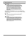
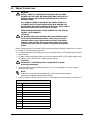
DANGER
VERIFY THAT ALL INCOMING HIGH AND LOW VOLTAGE
POWER CIRCUITS ARE DE-ENERGIZED AND LOCKED OUT
BEFORE INSTALLING CABLES OR MAKING ELECTRICAL
CONNECTIONS.
ALL POWER CONNECTIONS MUST BE COMPLETED BY A
LICENSED ELECTRICIAN EXPERIENCED IN WIRING UPS
EQUIPMENT, AND IN ACCORDANCE WITH ALL APPLICABLE
NATIONAL AND LOCAL ELECTRICAL CODES.
IMPROPER WIRING MAY CAUSE DAMAGE TO THE UPS OR
INJURY TO PERSONNEL.
!
CAUTION
All shielded cables, non-shielded cables, non-shielded control
wires, non-shielded battery breaker control wires, and nonshielded remote control wires must be housed in individual,
separate, steel conduits. Placing multiple cables in the same
conduit with other control or power wiring may cause system
failure.
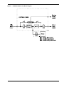
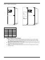
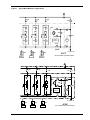
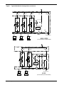
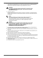
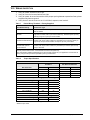
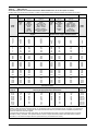
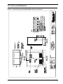
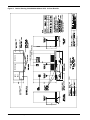
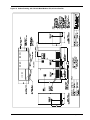
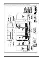
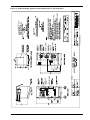
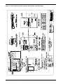
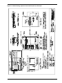
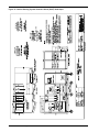
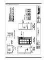
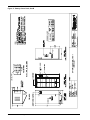
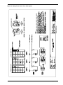
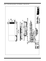
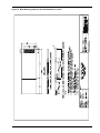
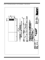
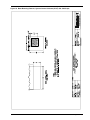
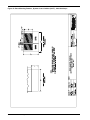
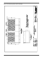
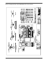
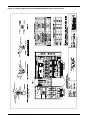
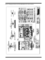
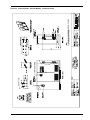
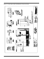
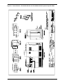
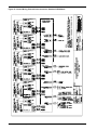
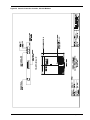
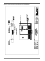
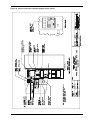
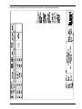
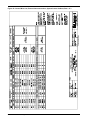
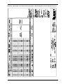
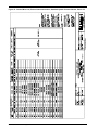
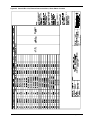
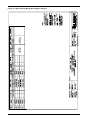
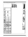
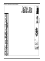
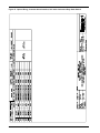
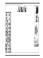
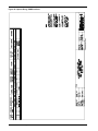
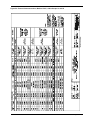
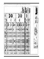
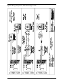
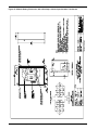
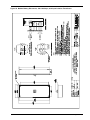
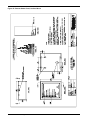
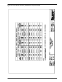
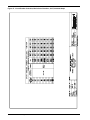
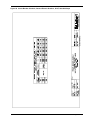
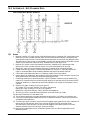
Refer to the drawings in this manual and any other drawings provided by Liebert for this installation. Make all of the following connections:
1. AC power cables from input power source circuit breaker (RIB) to UPS Module Input. Observe
phase rotation.
2. AC power cables from bypass power source circuit breaker (BIB) to UPS system bypass input
at System Control Cabinet (SCC). Observe phase rotation.
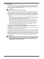
!
CAUTION
See Section 7 of this Manual for an explanation of proper
grounding techniques.
3. AC power cables from UPS Module Outputs to SCC or to switchgear for critical load bus.
Observe phase rotation.
NOTE
Make sure all required wiring between each UPS module and the optional
cabinet(s) is completed. Observe phase rotation.
4. Each UPS Module Output Neutral to SCC or to switchgear for critical load bus. See Section 7.
Abbreviations for Circuit Breakers
BFB
Bypass Feeder Breaker
BIB
Bypass Input Breaker
CB1
Module Input Breaker
CB2
Module Output Breaker
MBB
Maintenance Bypass Breaker
MBD
Module Battery Disconnect
MBFB
Maintenance Bypass Feeder Breaker
MIB
Maintenance Isolation Breaker
RIB
Rectifier Input Breaker
SBB
System Bypass Breaker
SBS
Static Bypass Switch
Wiring Connections
25