1
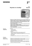
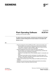
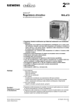
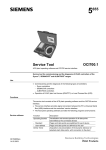
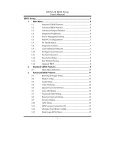
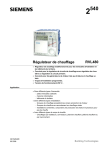
2 Heating Controller 527 Series B RVL469 for use with a partner unit • Multifunctional heating controller for use in residential and non-residential buildings; suitable for weather-dependent flow temperature control of heating zones with or without room temperature compensation • For exclusive use on the bus together with an RVL47... heatinmg controller as a partner unit • 1 programmed plant type: three-position control of the mixing valve in a heating zone • Analog or digital setting of the heating curve, analog room temperature readjustment, operating line principle for all other parameters • Operating voltage AC 230 V, CE conformity Use • Types of buildings: – Multi-family houses – Single-family houses – Smaller non-residential buildings • Types of plants: – Combined plants consisting of several heating zones and heat generation • Types of heating systems: – Radiator, convector, underfloor and ceiling heating systems, radiating panels Functions Heating zone control Operating modes Weather-dependent flow temperature control through control of the mixing valve in a heating zone in combined plants. Automatic mode Automatic changeover from normal to reduced temperature, and vice versa, according to the seven-day program, automatic changeover to holiday mode, demand-dependent control of heating system (ECO function) Setback mode Continuous heating to the reduced temperature, with ECO function Comfort mode Continuous heating to the normal temperature, no ECO function Standby Frost protection is ensured in all operating modes. The controller can be switched to manual operation. Siemens Building Technologies Landis & Staefa Division CE1N2527E / 04.03.1999 1/8 Other functions – – – – – Optimization functions Protective functions Remote control Commissioning aids Communication functions Ordering When ordering, please give type reference RVL469. Partner unit, sensors, actuator and valve and, if required, room unit must be ordered as separate items. Equipment combinations Partner unit Suitable partner units are: – RVL470 (data sheet CE1N2522E) – RVL471 (data sheet CE1N2524E) – RVL472 (data sheet CE1N2526E) – RVL47 (data sheet CE1N2523E) Suitable sensors and room units • Flow and return temperature: all sensors with LG-Ni 1000 Ω at 0 °C, for example: – Clamp-on temperature sensor QAD22 – Immersion temperature sensors QAE22... and QAP21.3 • Room temperature: – Room unit QAW50 – Room unit QAW70 – Room temperature sensor QAA24 • Outside temperature: – Outside sensor QAC22 (Ni sensing element) – Outside sensor QAC32 (NTC sensing element) Suitable actuators All electric and electrohydraulic actuators for three-position control made by Landis & Staefa can be used. For the different types of actuators, refer to data sheets 4500…4599. Communication The controller is capable of communicating with: – All units with LPB capability made by Landis & Staefa – SYNERGYR OZW30 central unit (from software version 3.0) Technical design Working principle Connection to an RVL47... partner unit is mandatory. The partner unit is defined by assigning an address. Each partner unit can be operated with only one RVL469. Plant type The RVL469 ha one plant type preprogrammed: room heating with mixing zone, threeposition control acting on mixing valve. BUS (LPB) B9 2527S01 A6/B5 E1 B7 A6 B1 B5 B7 B9 CE1N2527E / 04.03.1999 2/8 Room unit QAW50 or QAW70 Flow sensor Room sensor Return sensor Outside sensor E1 LPB M1 N1 Y1 Load (space) Data bus Heating circuit pump Controller RVL469 Mixing valve heating circuit Siemens Building Technologies Landis & Staefa Division Enduser settings With weather-dependent control, the flow temperature is controlled in function of the prevailing outside temperature via the heating curve. Its basic setting is made with the little bar on the front of the unit or on an operating line. The room temperature can be readjusted with the knob. In addition, following can be entered by the enduser: – Room temperature setpoints for normal heating, reduced heating and frost protection/holidays – Seven-day switching program and a maximum of eight holiday periods per year – Operating mode – Time of day and date Temperature acquisition – Flow temperature: with one or two (averaging) sensors – Outside temperature: with Ni or NTC sensor; the RVL469 identifies the type of sensor used; with interlinked controllers, it is also possible to define the source of the outside temperature – Room temperature: with a room temperature sensor or a room unit, or both (averaging) Space heating • The room temperature is included in the control. It can be acquired with a sensor or simulated by a room model with an adjustable building time constant. When using a sensor, the effect on the control can be adjusted. It is also possible to limit the maximum room temperature. • The heating is switched on and off depending on demand (ECO function). It is switched off when the amount of heat stored by the building mass is sufficient to maintain the required room temperature. In that case, the controller takes into account the development of the room temperature and the building's heat storage capacity. It is possible to set two heating limits, one for normal heating and one for reduced heating. • The control is optimized. Switching on, heating up and shutting down are controlled such that, during occupancy times, the required room temperature is always maintained. At the end of each occupancy period, the heating will be shut down (circulating pump) until the room temperature setpoint for the non-occupancy time is reached (quick setback, can be disabled). During heating up, the room temperature setpoint can be boosted (boost heating). It is possible to set maximum limits for the heating up time and for early shutdown. Three-position control Three-position control operates as weather-dependent or load-dependent flow temperature control. P-band and integral action time are adjustable. The flow temperature is controlled via the regulating unit (control or slipper valve). Minimum and maximum limitation of the flow temperature as well as maximum limitation of the rate of setpoint rise are adjustable. Minimum limitation of return temperature Minimum limitation of the return temperature acts with both three-position control and loaddependent control of the boiler temperature and helps prevent flue gas condensation. Locking functions On the software side, all settings can be locked to prevent unauthorized readjustments. Time switch – The RVL469 has one seven-day time switch for entering the daily occupancy times. Each day can accommodate three occupancy times, whereby each weekday may have different occupancy times – For entering a maximum of eight holiday periods, the RVL469 is equipped with a yearly time switch featuring automatic summer- / wintertime changeover Remote control – – – – Siemens Building Technologies Landis & Staefa Division Changeover of operating mode with the QAW50 room unit Overriding the major controller functions with the QAW70 room unit Selection of another (programmable) operating mode with an external contact Preselection of a fixed flow temperature setpoint with an external contact. Type of setpoint (fixed or minimum) and flow temperature can be selected CE1N2527E / 04.03.1999 3/8 Communication To provide this function, connection of the RVL469 to ist partner unit via the data bus is mandatory. Each RVL469 requires one partner unit. Communication with other units also takes place via the data bus and facilitates: – Signalling of heat demand to the heat source – Exchange of locking and enforced signals – Exchange of measured values such as outside temperature, return temperature, flow temperature and of clock signals – Communication with other devices – Reception of heat demand signals from the SYNERGYR OZW30 central unit (from software version 3.0) – Exchange of error messages Fault messages and flow temperature alarm – Fault message in the event of sensor faults – Fault message in the event of data bus faults – Flow temperature alarm; adjustable is a period of time during which the flow tempperature may stay outside the set limits; a fault message is given when the time has elapsed Other functions – – – – – – Display of parameters, actual values, operational statuses and fault messages Simulation of outside temperature Relay test; all relays can be controlled manually Sensor test; all measured values of the sensors can be displayed Testing the contacts connected to terminals H1–M and H2–M Outside temperature-dependent frost protection for the plant; a minimum flow temperature is maintained, its setpoint and the response threshold can be adjusted – Pump overrun time to prevent buildup of heat – Periodic pump run (pump kick) to prevent seizing of the pump in the summer – Controller hours run meter For more detailed information about technical features, functions and communication with LPB, please refer to the following pieces of documentation: – Basic Info RVL470: CE1P2522E – Data sheet “Basic System Data LPB“: CE1N2030E – Data sheet “LPB“: CE1N2032E Mechanical design The RVL469 is comprised of controller insert, which accommodates the electronics, the power section, the output relays and - on the front - all operating elements, and the base, which carries the connection terminals. The operating elements are located behind a lockable transparent cover. The operating instructions can be inserted in the transparent cover. The controller insert is secured to the base with two screws, one of which can be sealed. The cover can also be sealed. The RVL469 can be fitted in three different ways: – Wall mounting (on a wall, in the control panel, etc.) – Rail mounting (on a standard DIN mounting rail) – Flush panel mounting (control panel door, etc.) Analog operating elements – Buttons for selecting the required operating mode – Info button – Direct adjustment of the heating curve with the the little bar on the front of the unit (only if analog setting is selected) – Knob for manual readjustment of the room temperature – Three buttons for manual operation and manual positioning commands Digital operating elements The entry or readjustment of all setting parameters, activation of optional functions and reading of actual values and statuses is made according to the operating line principle. An operating line with an associated number is assigned to each parameter, each actual value and each function that can be selected. One pair of buttons is used to select an operating line and one pair to readjust the display. CE1N2527E / 04.03.1999 4/8 Siemens Building Technologies Landis & Staefa Division 2522Z04 1 2 3 4 5 6 7 8 9 10 11 12 13 14 Operating mode buttons (selected button is lit) Buttons for operating the display Prog = selection of operating line -- + = readjustment of displayed value Operating instructions Button for «Close valve» in manual operation Button for «Open valve» in manual operation Button for manual operation LEDs for: Manual operation Valve opens Valve closes Pump runs Sealing facility in the cover Info button for display of actual values Display (LCD) Setting slider for flow temperature setpoint at an outside temperature of –5 °C Setting slider for flow temperature setpoint at an outside temperature of 15 °C Knob for room temperature readjustments Fixing screw with sealing facility Notes Engineering The wires of the measuring circuits carry extra low voltage, those to the actuator and the pump carry AC 24…230 V. The local electrical regulations must be complied with. Sensor cables should not be run parallel to mains carrying cables for loads such as actuator, pump, etc. Commissioning The data bus address must be entered. The partner unit must be available on the data bus. Each controller is supplied complete with installation and commissioning instructions. Siemens Building Technologies Landis & Staefa Division CE1N2527E / 04.03.1999 5/8 Technical data Connection diagrams –conformity to EMC directive Immunity Emissions Low voltage directive Safety Rated operating voltage Frequency Power consumption Degree of protection (cover closed) Safety class Output relays Rated voltage Rated current Contact current at AC 24...90 V Contact current at AC 90...250 V Rated current of ignition transformer Switch-on current of ignition transformer Perm. ambient temperature Transport and storage Operation Perm. cable lengths to the sensors and external contacts Copper cable 0.6 mm dia. Copper cable 1.0 mm2 Copper cable 1.5 mm2 Perm. cable lengths to the room unit Copper cable 0.25 mm2 Copper cable from 0.5 mm2 Bus loading characteristic E (LPB) Backup of time switch Weight (net) 89/336/EWG EN 50082-2 EN 50081-1 73/23/EWG EN 60730-1 AC 230 V 50 Hz 8 VA IP42 EN 60529 II EN 60730 AC 230 V 2 (2) A 0.1...2 A, cos ϕ >0.6 0.02...2 A, cos ϕ >0.6 max. 1 A during max. 30 s max. 10 A during max. 10 ms -25...+65 °C 0...50 °C 20 m 80 m 120 m 25 m 50 m 6 12 h min. 1.1 kg Basic connections on the low voltage side S2 L D1 D2 B9 B7 H2 B5 N 2527A01 AC 230 V LPB 2527A02 AC 230 V Basic connections on the mains voltage side A6 B1 B5 B7 B9 LPB CE1N2527E / 04.03.1999 6/8 Room unit QAW50 or QAW70 Flow sensor Room sensor Return sensor Outside sensor Data bus M1 N1 S1 S2 Y1 Heating circuit pump Controller RVL469 Remote control operating mode Remote control flow temperature setpoint Actuator heating circuit Siemens Building Technologies Landis & Staefa Division Dimensions 139 1,5 144 95 (42,5) 15 144 19 26 26 26 26 144 max. 3 18 4,5 106 39 50 39 35 36 29 138 -0/+1 14 36 72 106 108 138 -0/+1 Dimensions in mm Siemens Building Technologies Landis & Staefa Division CE1N2527E / 04.03.1999 7/8 1999 Siemens Building Technologies Ltd. CE1N2527E / 04.03.1999 8/8 Siemens Building Technologies Landis & Staefa Division