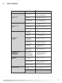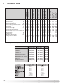
1
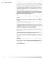
Instructions for Installation,
Servicing and Use
Unvented Hot Water Storage
Cylinders
Country of destination: GB/IE
TABLE OF CONTENTS
1.
THE BENCHMARK SCHEME
Page 2
2.
2.1
2,2
2.3
GENERAL INFORMATION
Guarantee
How the Appliance Works
Delivery
Page 3
Page 3
Page 3
Page 4
3.
3.1
3.2
3.3
3.4
3.6
3.7
3.8
3.9
3.10
3.11
3.12
3.13
3.14
INSTALLATION
Water Regulations
Building Regulations
General Guidance
Cold Water Supply
Siting and Fixing
Overall Dimensions
Connection of Mains Supply
Cold Water Combination Valve
Connection to Services
Secondary Return
Discharge Pipework
Electrical Connection
Electrical Diagrams
Page 5
Page 5
Page 5
Page 5
Page 5
Page 6
Page 7
Page 8
Page 11
Page 14
Page 14
Page 14
Page 17
Page 19
4.
COMMISSIONING
Page 24
5.
5.1
5.2
5.3
5.4
5.5
5.6
MAINTENANCE
ProTech Anti-corrosion System
Thermal Cut-out(s)
Immersion Heater(s)
Unvented Controls
Thermostats
Maintenance
Page 26
Page 26
Page 26
Page 26
Page 26
Page 27
Page 27
6.
FAULT FINDING
Page 29
7.
TECHNICAL INFORMATION
Page 30
8.
BENCHMARK COMMISSIONING CHECKLIST
Page 34
9.
BENCHMARK SERVICE RECORD
Page 35
1.
The Benchmark
Scheme
Benchmark places responsibilities on both manufacturers and installers.
The purpose is to ensure that customers are provided with the correct
equipment for their needs, that is installed, commissioned and serviced in
accordance with the manufacturer’s instructions by competent persons and
that it meets the requirements of the appropriate Building Regulations. The
Benchmark Checklist can be used to demonstrate compliance with Building
Regulations and should be provided to the customer for future reference.
Installers are required to carry out installation, commissioning and servicing
work in accordance with the Benchmark Code of Practice which is available
from the Heatinmg and Hotwater Industry Council who manage and promote
the Scheme. Visit www.centralheating.co.uk for more information.
2
2.
GENERAL
INFORMATION
This manual is an integral and essential part of the product. It should be kept
with the appliance so that it can be consulted by the user and/or authorised
personnel.
Please read carefully the instructions and notices about the appliance
contained in this manual, as they provide important information regarding the
safe installation, use and maintenance of the cylinder.
Failure to do so may invalidate the guarantee.
When installing and ser vicing the cylinder, Ariston Ther moUK Ltd
recommend the use of protective clothing i.e. gloves.
2.1
GUARANTEE
The MTS range of unvented cylinders come with varying guarantees
depending on the model of cylinder. The guarantee periods offered with
each model of cylinder are as follows:
ST Range
-
10 Years tank
2 Years electrical components
Classico Range
-
5 Years tank
2 Years electrical components
Primo Range
-
25 Years tank
2 Years electrical components
High Capacity Range
-
10 Years tank
2 Years electrical components
Note: The guarantee is subject to the cylinder being installed and serviced
annually by a competent person as per the servicing instructions in Section
5.6 of this manual. For units with the ProTech anti-corrosion device it must
be ensured that this is connected and operating correctly (green LED only).
2.2
HOW THE APPLIANCE
WORKS
The immersion heater(s) are controlled through a thermostat which senses
the water temperature. The operating temperature can be pre-set by
adjusting the spindle in the head of the thermostat. In addition to the
thermostat there is a thermal cut-out incorporated if the thermostat fails and
the water temperature rises too high. Once the cut-out operates it can only
be re-set manually after the fault has been rectified.
Indirect models have dual thermal controls. In addition to the above there is a
separate cylinder thermostat and thermal cut-out for controlling each indirect
circuit. Again the thermal cut-out operates if the cylinder thermostat fails, by
disconnecting the live feed (call for hot water) from the programmer.
ITI/ITD/ITSI models have a stainless steel tank and therefore need no
protection against corrosion.
STD/STI models have an enamelled steel tank and therefore are supplied
with magnesium anodes to prevent corrosion of the cylinder tank. It is
imperative that the top anode is checked during the annual service and if
found to be corroded both anodes should be replaced. Failure to do so could
invalidate the warranty of the tank.
All High Capacity (STD/STI) 500 litre models and Wall-hung (ST) units utilise
the ProTech anti-corrosion system (electronic anode). This prevents an
electrolytic reaction between the tank and dissimilar metals. The ProTech
system shows if it is operating correctly (green LED) or incorrectly (red LED).
In the event that the red LED lights (even with the green light still showing), it
is imperative that a service agent is contacted immediately as continued use
with the ProTech system in this state could invalidate the warranty on the
tank.
3
The factory fitted temperature & pressure relief valve at the top of the
cylinder is a safety device to back-up the thermostat(s) and thermal cutout(s). It works by sensing an excess in water temperature or pressure and
releasing the hot water into a discharge tundish and drain.
The cylinder will only work in the vertical position. The inlet pipe needs to
deliver cold water to the bottom of the tank. When water is heated it expands.
To accommodate this increase in volume an expansion vessel is provided. A
cold water combination valve is also provided in two pieces, loose jointed for
ease of installation. These comprise a combined line strainer/pressure
reducing valve and core non-return valve/expansion relief valve.
2.3
DELIVERY
The Ariston range of Unvented Cylinders are available in the following
options:
The Wall-hung ProTech range (50, 80, 100 litre models), which are supplied
as follows;
One box containing;
1) The cylinder with factory fitted temperature & pressure relief valve,
immersion heater and thermostat with thermal cut-out.
One box containing;
1) Unvented control pack (expansion vessel, 2 piece cold water combination
valve and tundish), instructions for installation, servicing and use and the
Benchmark Log Book).
The High Capacity ProTech floor-standing range (500 litre models), which
are supplied as follows;
One box containing;
1) The cylinder with factory fitted temperature & pressure relief valve.
One box containing;
1) Unvented control pack (expansion vessel, 2 piece cold water combination
valve and tundish), motorised valve (indirect only, non-high temperature).
Immersion heater(s) and thermostat(s) with thermal cut-out(s), cylinder
thermostat with thermal cut-out (indirect only), feet (x 3), instructions for
installation, servicing and use and the Benchmark Log Book.
The STD and STI floor standing range (125, 150, 200 and 300 litre models)
and the ITD and ITI floor standing range (100, 125, 150, 175, 200, 250 and
300 litre models which are supplied as follows;
One box containing;
1) The cylinder with factory fitted temperature & pressure relief valve.
One box containing;
1) Unvented control pack (expansion vessel, 2 piece cold water combination
valve and tundish), motorised valve (indirect only, non-high temperature).
Immersion heater(s) and thermostat(s) with thermal cut-out(s), cylinder
thermostat with thermal cut-out (indirect only), feet (x3), expansion vessel
mounting bracket and hose, instructions for installation, servicing and use
and the Benchmark Log Book.
The ITSI twin coil floor standing range (200, 250 and 300 litre models) are
supplied with the following;
One box containing;
1) The cylinder with factory fitted temperature & pressure relief valve.
One box containing;
1) Unvented control pack (expansion vessel, 2 piece cold water combination
4
valve and tundish), 2 x motorised valves (non-high temperature), 2 x
Immersion heaters and thermostats with thermal cut-out, 2 x cylinder
thermostats with thermal cut-out, 1 x elongated thermostat pocket (for
solar applications), feet (x3), expansion vessel mounting bracket and
hose, instructions for installation, servicing and use and the Benchmark
Log Book.
3.
INSTALLATION
3.1
WATER REGULATIONS
3.2
BUILDING REGULATIONS
3.3
GENERAL GUIDANCE
The appliance should be installed in accordance with the Domestic Heating
Compliance Guide.
These regulations (byelaws in Scotland) ensure a good supply of
wholesome water, and that only approved materials, pipes and fittings are
used to convey water.
These are a statutory document and take priority over all other regulations
and recommendations. The installation of an unvented hot water storage
cylinder is classified as a “Controlled Service” and Regulation G3 applies. To
meet the requirements of the Regulation, installation of an unvented system
should be undertaken by a “competent installer”.
All installations of unvented hot water storage systems having a capacity of
more than 15 litres should be notified to the relevant Local Authority by
means of building notice or by the submission of full plans. It is important to
note that it is a criminal offense to install an unvented hot water storage
system without notifying the Local Authority. The installation of the unvented
cylinder and hot water system must comply with BS 6700 and the HSE
Legionella Code of Practice.
Current guidance notes do not cover the connection of a solar thermal
circuit to an unvented storage vessel (cylinder). However, if guidance is
sought for compliance with current regulations the fundamental principle is
to provide a failsafe means of shutting off the solar input to the heat
exchanger if the cylinder temperature should rise above the set temperature
of the cylinder’s energy cut out. (See Note 1).
As with all unvented hot water systems, notification of intention to install
should be given to your local building control.
Option A. A non self resetting mechanical shut-off should be installed on
the solar primary flow to the cylinder. The mechanical shut-off should be
suitable for use with a solar primary circuit (i.e. high temperature and glycol
resistant). The mechanical shut-off should be integrated electrically with the
cylinder energy cut out/s and if necessary the solar circuit temperature
control, please refer to the solar controller manufacturer for further
information.
Option B. Where the solar controller and hydraulic system demonstrate that
by no lesser means the requirement in Option A is satisfied by other means;
certification by an approvals body is required to demonstrate that in the
event of the stored water going over temperature, the heat input to the
cylinder is isolated by physical means and is non self resetting.
These systems should be clearly identified with reference to the approvals
body. (See Note 2)
Note 1 :Whilst most solar cylinders use a coil type heat exchanger other
options such as external plate to plate devices , external annulars or ‘tank in
tank’ systems may be used but the same control options always apply.
Note 2 :Current approved bodies include the British Board of Agrement
(BBA) , WRc-NSF Limited, or KIWA
3.4
COLD WATER SUPPLY
The strainer prevents any debris entering the other controls. The pressure
reducer ensures the correct operation of the expansion vessel, and prevents
any damage to the control valves through too great a pressure.
The non-return valve ensures the water expansion is forced into the
expansion vessel and prevents contamination of the mains cold water
supply. The expansion relief valve will discharge expanded water to the
discharge tundish if the expansion vessel fails.
5
3.6
SITING AND FIXING
It is important to ensure that the cold water main is capable of supplying the
increased demand which will be imposed on it. Hot and cold water are both
drawn off the same source of supply. Remember, there will not be a storage
tank to help compensate for variations in the demand on the system.
A minimum pressure of approximately 1.5 bar and 20 litres per minute is
required for satisfactory operation. 85% of UK dwellings have a mains
pressure above 2.0 bar.
NOTE: THE MAINS WATER SUPPLY MUST NOT EXCEED 16 BAR.
The cylinder should be left packed until it is time to install. When unpacking
the appliance follow the guidelines within the packaging and take care not to
damage the temperature and pressure relief valve.
The cylinder may be installed in any convenient position. As it is connected
to the mains cold water supply, it is equally effective on any floor, however,
consideration must be given to allow ease of access for maintenance
purposes.
Additionally, do not install the unit in premises which may be subject to
freezing.
Ensure that the floor load bearing strength is adequate to take the weight of
the cylinder when full of water (see TABLE 1).
The ST50, ST80 and ST100 ProTech models are wall mounted. All other
models are free standing. These are supplied with feet which are attached to
the heater via self-tapping screws which are also supplied.
All units must be installed in the VERTICAL POSITION.
For maintenance purposes leave at least 500 mm free space in front of the
unit, for access.
IMPORTANT: In the event that the installation of this cylinder wil require a third
sensor to be fitted (i.e. Solar) the following actions will be necessary:
Replace one of the ther mostat pockets supplied with the indirect
thermostats in the Unvented Kit with the elongated thermostat pocket also
supplied.
This thermostat and pocket must now be fitted to the top thermostat
connection.
Please also refer to Section 2.3 General Guidance Options A and B (page
5) of this manual.
For further technical advice, please contact the Ariston Technical Advice
Line on 0870 241 8180.
6
Storage
Contract STI 125
Contract STI 150
Contract STI 210
Contract STI 300
500 STI ProTech
125 l
150 l
200 l
300 l
495 l
125 l
150 l
200 l
300 l
495 l
Floor Standing
Contract STD 125
Contract STD 150
Contract STD 210
Contract STD 300
500 STD ProTech
INDIRECT RANGE
50 l
75 l
100 l
Capacity
DIRECT RANGE
Wall-hung
ST 50 ProTech
ST 80 ProTech
ST 100 ProTech
Model
3/4”
3/4”
3/4”
3/4”
1"
3/4”
3/4”
3/4”
3/4"
1”
1/2”
3/4”
3/4”
Inlet Outlet
Units Pipe Size
ST ProTech
50-80-100
0.75
0.9
0.9
0.9
1.5
-
-
Coil
Surface
m2
Contract STD
125-150-200-300
650
790
940
1210
1390
650
790
940
1210
1390
410
590
550
A
747
905
1221
1555
335
747
905
1221
1551
335
120
175
175
B
995
1155
1475
1790
1870
1015
1165
1495
1795
1870
580
740
700
C
Contract STI
125-150-200-300
625
765
765
815
700
-
160
230
230
D
-
-
475
475
575
E
Dimensions in mm
505
505
505
560
714
505
505
505
505
714
460
460
560
F
265
265
265
275
-
265
265
265
265
-
-
G
500 STD ProTech
500 STI ProTech
225
225
225
255
-
-
-
H
-
-
-
I
-
-
-
J
166
201
256
395
641
129
158
190
245
625
77
115
141
Weight
When Full
Kg
TABLE 1
3.7
OVERALL DIMENSIONS
7
8
PRIMO ITI 100
PRIMO ITI 125
PRIMO ITI 150
PRIMO ITI 175
PRIMO ITI 210
PRIMO ITI 250
PRIMO ITI 300
PRIMO ITSI 210 (top/bottom)
PRIMO ITSI 250 (top/bottom)
PRIMO ITSI 300 (top/bottom)
INDIRECT RANGE
PRIMO ITD 100
PRIMO ITD 125
PRIMO ITD 150
PRIMO ITD 175
PRIMO ITD 210
PRIMO ITD 250
PRIMO ITD 300
DIRECT RANGE
Model
Storage
100l
125l
150l
175l
200l
250l
300l
200l
250l
300l
100 l
125 l
150 l
175 l
200 l
250 l
300 l
Capacity
3/4"
3/4”
3/4”
3/4”
3/4”
3/4”
3/4”
3/4”
3/4”
3/4”
3/4”
3/4”
3/4”
3/4”
3/4”
3/4”
3/4”
Inlet Outlet
Units Pipe Size
PRIMO ITD
100-125-150-175-200-250-300
0.5
0.67
0.80
0.80
0.90
0.90
0.90
0.67/0.67
0.67/0.67
0.67/0.89
-
Coil
Surface
m2
492
650
790
869
940
990
1210
940
990
1210
492
650
790
869
940
990
1210
A
589
747
905
1063
1221
1316
1551
1221
1316
1551
589
747
905
1063
1221
1316
1551
B
845
1015
1165
1335
1495
1555
1795
1495
1555
1795
845
1015
1165
1335
1495
1555
1795
C
PRIMO ITI
100-125-150-175-200-250-300
555
625
765
765
765
795
795
625
655
795
-
D
-
-
E
Dimensions in mm
505
505
505
505
505
560
560
505
560
560
505
505
505
505
505
560
560
F
265
265
265
265
265
270
270
265
270
270
265
265
265
265
265
270
270
G
PRIMO ITSI
210-250-300
225
225
225
225
225
255
255
225
255
255
-
H
806
876
1111
-
I
1206
1276
1511
-
J
123
155
180
211
238
297
348
238
297
349
122
156
183
208
239
297
344
Weight
When Full
Kg
TABLE 1
3.8
CONNECTION OF MAINS
WATER SUPPLY
For floor standing models:
On the front of the unit there is a label to identify the connection ports.
Please check this before making any connection to the unit.
For units up to 300 litres it is recommended that all mains cold water supply
pipe work is a minimum of 22mm, with the exception of model ST 50
ProTech where 15mm can be used. For 500 litre models the supply should
be 28mm. An isolating valve should be installed between the cold water
supply and the cylinder for servicing. ALL PIPEWORK MUST BE FLUSHED
TO AVOID DAMAGE TO THE CONTROL VALVES.
Please refer to FIGS. 3.1 - 3.7 for a suggested installation layout.
When installing the expansion vessel it can either be connected directly to
the combination valve (see Figs 3.8 - 3.10), or it can be installed remotely
using the flexible hose supplied.
IMPORTANT NOTE:When installing the expansion vessel, DO NOT install the expansion vessel
vertically as air can become trapped in the expansion vessel resulting in
potential vibrations through the cylinder and pipework. When using the
flexible hose to remotely install the expansion vessel away from the control
valve, again, ensure that the vessel is not installed in a vertical position
where it can trap air.
See below for acceptable installation practices.
4
8
4
9
STD 125-150-210-300 DIRECT
ITD 125-150-175-210-250-300 DIRECT
ST PROTECH 50-80-100
PRESSURE + TEMPERATURE
RELIEF VALVE
COMBINATION
VALVE
COLD
MAINS-IN
22mm
COLD
MAINS-IN
15/22mm
EXPANSION
VESSEL
COMBINATION
VALVE
15mm
EXPANSION
VESSEL
PRESSURE + TEMPERATURE
RELIEF VALVE
HOT SUPPLY
22mm
HOT SUPPLY
15/22mm
EXPANSION RELIEF
PIPE
EXPANSION
RELIEF
PIPE
SECONDARY
RETURN
TUNDISH
TUNDISH
22mm
22mm
MAX. 100mm
DRAIN
MAX. 100mm
FIG. 3.2
FIG. 3.1
ITSI 210-250-300 TWIN COIL INDIRECT
(DUAL HEAT SOURCE)
STI 125-150-210-300 INDIRECT
ITI 100-125-150-175-210-250-300 INDIRECT
COMBINATION
VALVE
COLD
MAINS-IN
22mm
COMBINATION
VALVE
EXPANSION
VESSEL
EXPANSION
VESSEL
PRESSURE + TEMPERATURE
RELIEF VALVE
PRESSURE + TEMPERATURE
RELIEF VALVE
HOT SUPPLY
22mm
HOT SUPPLY
22mm
EXPANSION RELIEF
PIPE
SECONDARY
RETURN
TUNDISH
COLD
MAINS-IN
22mm
FLOW
EXPANSION RELIEF
PIPE
SECONDARY
RETURN
ZONE
VALVE
ZONE
VALVE
TUNDISH
RETURN
FLOW
FLOW
22mm
22mm
ZONE
VALVE
DRAIN
DRAIN
RETURN
MAX. 100mm
FIG. 3.3
10
RETURN
MAX. 100mm
NOTE: FLOW AND RETURN PIPES MAY BE CONNECTED IN REVERSE
TO THAT SHOWN IN THE DIAGRAMS FOR INDIRECT CYLINDERS.
FIG. 3.4
ITSI 210-250-300 INDIRECT (LINKED COILS)
500 STI PROTECH
COLD
MAINS-IN
28mm
COMBINATION
VALVE
COMBINATION
VALVE
COLD
MAINS-IN
22mm
EXPANSION
VESSEL
EXPANSION
VESSEL
HOT SUPPLY
28mm
PRESSURE +
TEMPERATURE
RELIEF VALVE
PRESSURE + TEMPERATURE
RELIEF VALVE
HOT SUPPLY
22mm
EXPANSION RELIEF
PIPE
FLOW
ZONE
EXPANSION RELIEF
VALVE
PIPE
SECONDARY
RETURN
RETURN
TUNDISH
SECONDARY
RETURN
ZONE
VALVE
TUNDISH
FLOW
FLOW
22mm
22mm
DRAIN
DRAIN
RETURN
RETURN
MAX. 100mm
MAX. 100mm
FIG. 3.6
FIG. 3.5
500 STD PROTECH
COLD
MAINS-IN
28mm
COMBINATION
VALVE
EXPANSION
VESSEL
HOT SUPPLY
28mm
PRESSURE +
TEMPERATURE
RELIEF VALVE
EXPANSION RELIEF
PIPE
SECONDARY
RETURN
TUNDISH
22mm
DRAIN
MAX. 100mm
FIG. 3.7
11
3.9
COLD WATER
COMBINATION VALVE
The cold water combination valve may be fitted in close proximity to the
cylinder, or alternatively, it may be separated to allow the pressure reducing
valve where the mains supply enters the property allowing for balanced cold
water throughout the whole property whilst the 6 bar safety valve is fitted in
close proximity to the cylinder.
A balancing port is supplied on the 22mm valves (for units above 50 litres)
and 28mm valves (for 500 litres units) allowing balanced cold water supply
to the rest of the building giving constant results for mixer and shower
valves. If the facility is not needed a plug is supplied. Refer to FIG. 3.9 and
FIG. 3.10
Although this facility is not built into the 15mm valve (supplied with model
ST50), a tee piece may be inserted between the two components giving the
same result. Refer to FIG. 3.8
NOTE!
THERE
SHOULD BE NO OTHER VALVES FITTED BETWEEN THE CYLINDER AND THE
EXPANSION VALVE.
SERVICEABLE 1/2” PRESSURE
REDUCING CARTRIDGE AND
LINE STRAINER
NON-RETURN
VALVE (WITHIN HOUSING)
EXPANSION RELIEF
VALVE (SET AT 6 BAR)
15mm
COLD
MAINS IN
15mm
TO CYLINDER
TEE PIECE
FOR BALANCED
COLD WATER
TAKE OFF
(NOT SUPPLIED)
FIG. 3.8
12
3/4” B.S.P. CONNECTIONS
FOR EXPANSION VESSEL
For Model ST 50
3/4” B.S.P. CONNECTION
FOR EXPANSION VESSEL
22mm COLD
MAINS IN
22mm TO WATER HEATER
15mm EXPANSION RELIEF
OUTLET TO TUNDISH
SERVICEABLE 3/4” PRESSURE REDUCING
CARTRIDGE AND LINE STRAINER
(SET AT 3.5 BAR)
EXPANSION RELIEF VALVE
(SET AT 6 BAR)
22mm COLD
MAINS IN
22mm TO CYLINDER
NON-RETURN VALVE
(WITHIN HOUSING)
22mm BALANCED COLD WATER TAKE OFF
WITH NON-RETURN VALVE
FIG. 3.9
For ST 80 and 100, Primo ITD, ITI, ITSI,
Classico STD and STI models
SERVICEABLE 1” PRESSURE REDUCING
CARTRIDGE AND LINE STRAINER
(SET AT 3.5 BAR)
EXPANSION RELIEF VALVE
(SET AT 6 BAR)
28mm COLD
MAINS IN
28mm TO
CYLINDER
3/4” B.S.P. CONNECTION
FOR EXPANSION VESSEL
FIG. 3.10
1” BALANCED COLD WATER TAKE OFF
WITH NON-RETURN VALVE
For 500 litre
Models
13
3.10
CONNECTION TO SERVICES
It is recommended that a 22mm pipe run should supply the outlets
throughout the building, especially to baths and showers. Short runs of
15mm pipe may be used to connect basins and sinks.
3.11
SECONDARY RETURN
On floor-standing models a secondary return may be fitted (consult the label
on the face of the unit for the correct location). A non-return valve (not
supplied) must be fitted to prevent back flow and a bronze pump will be
needed in conjunction with a pipe thermostat and timer to circulate the hot
water (both not supplied).
NOTE: an extra expansion vessel may be required where the additional
volume of the secondary return exceeds the capacity of the expansion
vessel supplied.
3.12
DISCHARGE PIPEWORK
NOTE!
THE SAFETY RELIEF VALVES MUST NOT BE USED FOR ANY OTHER PURPOSE
1) Discharge pipes from the temperature & pressure relief and expansion
relief valve may be joined together.
2) The tundish must be vertical and fitted within 500mm of the temperature
& pressure relief valve and must be located with the cylinder. The tundish
must also be in a position visible to the occupants, and positioned away
from any electrical devices. The discharge pipe from the tundish should
of metal and terminate in a safe place where there is no risk to persons
in the vicinity of the discharge.
3) The pipe diameter must be at least one pipe size larger than the nominal
outlet size of the safety device unless it's total equivalent hydraulic
resistance exceeds that of a straight pipe 9m long.
i.e. Discharge pipes between 9m and 18m equivalent resistance length
should be at least 2 sizes larger than the nominal outlet size of the safety
device. Between 18m and 27m at least 3 larger, and so on.
Bends must be taken into account in calculating the flow resistance.
See FIG. 3.11 and TABLE 2.
4) The discharge pipe must have a vertical section of pipe at least 300mm
in length below the tundish, before any elbows or bends in the pipework.
5) The discharge pipe must be installed with a continuous fall and should be
at least one pipe diameter clear of the wall where it terminates.
6) The discharge should be visible at both the tundish and the final point of
discharge, but where this is not possible or practically difficult; there
should be clear visibility at one or other of these locations. Examples of
acceptance are:
i) Ideally below a fixed grating and above the water seal in a trapped
gully.
ii) Downward discharges at a low level; i.e. up to 100mm above
external surfaces such as car parks, hard standings, grassed
areas etc. These are acceptable providing that where children
may play or otherwise come into contact with discharges, a wire
cage or similar guard is positioned to prevent contact, whilst
maintaining visibility.
iii) Discharges at high level; Onto a roof capable of withstanding high
temperature discharges of water 3m from any plastic guttering
systems that would collect such a discharge (tundish visible).
iv) Where a single pipe serves a number of discharges, such as in
blocks of flats, i.e. into a metal hopper and metal down pipe with
the end of the discharge pipe clearly visible (tundish visible or
not). the number served should be limited to not more than 6
systems so that any installation can be traced reasonably easily.
14
The single common discharge pipe should be at least one pipe
size large than the largest individual discharge pipe to be
connected. If unvented hot water storage systems are installed
where discharges from safety devices may not be apparent i.e. in
dwellings occupied by the blind, infirm or disabled people,
consideration should be given to the installation of an
electronically operated device to warn when discharge takes
place.
Note: The discharge will consist of scalding water and steam.
Asphalt, roofing felt and non-metallic rainwater goods may be
damaged by such discharges.
Temperature & pressure
relief valve
Metal discharge pipe (D1) from
temperature & pressure relief valve.
to tundish.
Tundish
500mm Max.
300mm
Min.
Discharge below
fixed grating.
(see page 10 for
alternative points
of discharge).
Metal discharge pipe (D2) from tundish
with continuous fall. See Table 2 and worked
example.
Fixed grating
Trapped gulley
FIG. 3.11
TABLE 2. Sizing of copper discharge pipe “D2” for common temperature valve outlet sizes.
Valve outlet size
Minimum size of
discharge pipe D1*
Minimum size of
discharge pipe D2*
from tundish
Maximum
resistance allowed,
expressed as a
length of pipe (i.e.
no elbow or bends)
Resistance created
by each elbow or
bend
G 1/2
15mm
G 3/4
22mm
G1
28mm
22mm
28mm
35mm
28mm
35mm
42mm
35mm
42mm
54mm
Up to 9m
Up to 18m
Up to 27m
Up to 9m
Up to 18m
Up to 27m
Up to 9m
Up to 18m
Up to 27m
0.8m
1.0m
1.4m
1.0m
1.4m
1.7m
1.4m
1.7m
2.3m
15
WORKED EXAMPLE
The example below is for a G1⁄2 temperature & pressure relief valve with a
discharge pipe (D2) having 4 no. elbows and length of 7m from the tundish
to the point of discharge.
From TABLE 2;
Maximum resistance allowed for a straight length of 22mm copper discharge
pipe (D2) from G1⁄2 temperature & pressure valve is 9m. Subtract the
resistance for 4 no. 22mm elbows at 0.8m each = 3.2m. Therefore the
maximum permitted length equates to: 5.8m. As 5.8m is less than the actual
length of 7m therefore calculate the next largest size.
Maximum resistance allowed for a straight length of 28mm pipe (D2) from
G1⁄2 temperature & pressure valve equates to: 18m. Subtract the resistance
for 4 no. 28mm elbow at 1.0m each = 4m. Therefore the maximum permitted
length equates to: 14m
As the actual length is 7m, a 28mm (D2) copper pipe will be satisfactory.
WARNINGS
The outlet from the temperature & pressure relief valve must not be used for
any other purpose. This also applies to the expansion relief valve. No other
valve is to be fitted between the cold water combination valve and the
cylinder.
The temperature & pressure relief valve must not be removed in any
circumstances. Any of the above will totally invalidate the guarantee.
16
3.13 ELECTRICAL
CONNECTION
The electrical installation must be in accordance with the current I.E.E.
wiring regulations.
PROTECH ELECTRONIC ANTI-CORROSION SYSTEM (ST Range & 500
litre models only)
I MPORTANT : The ProTech anti-corrosion system MUST be permanently
connected to a fused non-switched 240V electricity supply see FIG 3.12.
Anode circuit
L 1
N
Electronic anode
FIG. 3.12
240V~
The ProTech system, an exclusive solution, is an electronic anti-corrosion
protection system which ensures maximum longevity of the appliance,
regardless of water quality. The electronic circuit creates a difference in
potential between the hot water tank and the titanium electrode, thereby
guaranteeing optimum protection of the tank and preventing corrosion.
To ensure the proper operation of the protection system, IT MUST BE
PERMANENTLY CONNECTED TO A FUSED NON-SWITCHED 240V, 3A
ELECTRICITY SUPPLY even in the event of shut-down of the system. To
prevent risk to the appliance’s lifespan when disconnecting the protection
system for an extended period of time, it is necessary to drain the appliance
beforehand.
In addition to the 240V network, the electronic circuit is also connected to
the tank, which is to be protected, and to the titanium protection electrode,
INFORMATION FOR THE END USER
Proper operation of the protection system is shown by a continuous green
L.E.D, indicating that the circuits terminals are being supplied with electricity.
In the event of failure, a red L.E.D. indicates that there is a short-circuit
between the electrode and the cylinder tank, that one of the leads (tank or
electrode) is disconnected or that there is no water in the cylinder.
Your appliance is thus properly protected when the green L.E.D. is
illuminated and the red L.E.D. is off. Should this not be the case, please
contact your installer.
17
FITTING IMMERSION HEATER(S) (100 - 300 litre foor standing only)
These are supplied with but not fitted to 100 - 300 floor-standing models. A
sealing gasket is supplied with each element, however the use of a suitable
sealing compound is recommended to ensure a correct seal. Care must be
taken not to cross thread the immersion heater(s) when fitting. Each
immersion heater is supplied with a regulation thermostat and manual reset
thermal cut-out. This will activate if the regulation thermostat fails. Under no
circumstances should this be by-passed. The immersion heaters supplied
are rated at 3kW.
Note!
The immersion heaters must not be fitted without the
thermostat/thermal cut-out.
DIRECT SYSTEMS
A mains supply of 240V, 3kW (13 amps) is required. Heat resistant cable,
round 3 or 4 core 2.5mm2 (to BS6141 table 8) must be used to connect the
electrical supply through the Economy 7 time control switch using either
system ‘A’ or ‘B’ as illustrated in Fig. 3.11.
SYSTEM A
FIG. 3.13
18
SYSTEM B
3.14
ELECTRICAL DIAGRAMS
Should the Economy 7 system not to be used, a separate 13 amp supply to
each element will be required through a double pole fused isolating switch
having a contact gap of at least 3mm on each pole.The immersion heater
shall be installed with 85°C rubber insulated HOFR-sheathed flexible cable
complying with Table 8 of BS 6141: 1991. Make the connection(s) to the
immersion heater(s) as per FIG. 3.14 and FIG. 3.15. For High Capacity 500
litre models see FIG. 3.16 (page 20).
Single Element
THERMAL
CUT-OUT
THERMOSTAT
ELEMENT
3 kW
L1
240V~
N
FIG. 3.14
THERMAL
CUT-OUT
THERMOSTAT
L1
DAY ELEMENT
3 kW 240V~
N
THERMAL
CUT-OUT
THERMOSTAT
L2
NIGHT ELEMENT
3 kW 240V~
ECONOMY 7
N
FIG. 3.15
19
20
Live Supply from
common fused spur
FIG. 3.16
IMPORTANT: WHEN WIRING THE 500 LITRE CYLINDERS IMMERSION HEATER ENSURE THAT A
SUITABLE HEAT RESISTANT CABLE RATED ABOVE THE PROTECTIVE DEVICE IS USED (I.E.
6MM FOR 32AMP).
Earths omitted for clarity
Neutral
L3
L2
L1
4
2
3
1
Neutrals to be connected
using amp tag connectors
Live wires supplied in kit
Switched Live
5
Terminals
6
SINGLE PHASE WIRING INSTRUCTIONS FOR
6KW IMMERSION HEATER
CLAS HE both zones timed
from integral timer
GENUS Range program time
zones 1 & 2 on digital display
NOTE:
Enable Parameter 223
and change from 0 to 1
Wiring diagram for two 2 Port Valves with Ariston GENUS HE, CLAS HE
and CLAS boilers with 2 zone clip in fitted.
FIG. 3.17
NOTE: WITH REGARDS TO THE PRIMO ITSI CYLINDERS, FOR
MORE DETAILED WIRING INSTRUCTIONS PLEASE CONTACT
THE TECHNICAL DEPARTMENT ON
0870 241 8180.
21
Wiring diagram for two 2 Port Valves
FIG. 3.18
NOTE:
WITH REGARDS TO THE PRIMO ITSI CYLINDERS, FOR
MORE DETAILED WIRING INSTRUCTIONS PLEASE CONTACT
THE TECHNICAL DEPARTMENT ON
22
0870 241 8180.
Wiring diagram for a 3 Port Valve & 2 Port Valve
FIG. 3.19
23
4.
COMMISSIONING
The thermostat(s) on the immersion heater(s) should be adjusted to trip at
60-65°C. This is the ideal temperature to prolong element life in hard water
areas. Scale on the sheath builds up more rapidly at temperatures above
this causing the element to overheat and premature failure can occur. Higher
temperatures without additional controls would result in scalding. In known
hard water areas the use of a scale inhibitor is also recommended.
In addition to the thermostat the thermal cut-out will switch power off to the
element should the thermostat malfunction, causing an excessive rise in
water temperature. The thermal cut-out can be reset manually after the fault
has been corrected.
INDIRECT SYSTEMS
For models up to 300 litres a mains supply of 240V, 3kW (13 amps) will be
required for the direct immersion heater. heat resistant cable, round 3 core
2.5mm2 (to BS6141) must be used. For High Capacity 500 litre models
consult the wiring diagram on the reverse of the inspection panel.
For indirect controls a 240V, 3 amp supply is required.
On floor standing models it is necessary to fit the thermostat using P.T.F.E
tape (Please consult the label on the face of the unit for the correct location
in both cases).
The cables must be clamped in position (as previously stated) and the
control thermostat should be set at 60°C for the reasons above. In addition
to the thermostat there is a thermal cut-out should the thermostat fail. Refer
to FIG. 3.15.
WARNING : THE APPLIANCE MUST BE EARTHED.
The earth continuity conductor of the electrical installation must be
effectively connected to all exposed parts of other appliances and services
in the room in which the water heater is to be installed and conform to the
I.E.E. wiring regulations.
NOTE: Do not switch on the immersion heater or fire the boiler until the
cylinder is full of water.
Check for obvious signs of damage to the cylinder and controls, and also
that the controls fitted correspond with the references quoted in these
instructions.
Ensure that the drain cock at the base of the appliance is closed before
commencing.
1) ProTech Models Only. Ensure that the ProTech anti-corrosion system is
connected to the electrical supply;
2) Ensure that the line strainer (situated in the pressure reducing valve) is
clear of installation debris and clean if necessary;
3) Check that the pressure in the expansion vessel is the same as the
incoming water pressure;
4) Open all outlet taps;
5) Turn on mains water supply and allow the water heater to fill;
6) Ensure that the hot water system is flushed in accordance with BS 6700;
7) Close taps in turn after having purged the system of air;
24
8) Check for leaks around the controls and immersion heaters and again
after the unit has heated up;
9) Check that no water is passing to waste through the relief valves;
10) Test the operation of the temperature & pressure relief and expansion
valves by lifting/turning the manually operated test lever/cap and
observing that water flows through freely and safely to waste;
11) Check that the discharge pipe is plumbed so that it falls continuously
and that no taps, valves or other shut off devices are installed in the
pipe;
12) Check that all thermostats are set at approximately 60-65°C;
13) DIRECT UNITS. Switch on immersion heater(s) and allow unit to heat
up. Check operation of thermostat(s);
14) INDIRECT UNITS. Fill the indirect (primary) circuit following the boiler
instructions. Switch on the boiler, ensure that the programmer is in the
domestic hot water position. Allow unit to heat up and check operation of
indirect thermostat on motorised valve(s);
15) Check the temperature of the hot water at the nearest outlet and record
in the Benchmark Log Book;
16) Demonstrate operation to user, including operation of temperature &
pressure relief valve and what to do if it operates;
17) Give this manual along with the completed Benchmark Log Book to the
user to retain for future reference and make the customer aware that
periodic checks of the equipment are essential for safety.
25
5.
MAINTENANCE
To ensure efficient and safe operation, and to maintain the warranty, it is
necessary to ensure the appliance is serviced annually by a competent
person.
Before servicing, preliminary electrical system checks must be carried out to
ensure electrical safety (i.e. polarity, earth continuity, resistance to earth and
short circuit).
5.1
PROTECH
ANTI-CORROSION SYSTEM
WARNING: SWITCH OFF THE POWER SUPPLY BEFORE WORKING ON
THE APPLIANCE.
Trouble-shooting:
1) The green L.E.D. is NOT on:
- Check to see that the circuits electric plug is connected (if not,
connect);
- Check to see that the P.C.B, is supplied with electricity (if not, replace
the supply cable);
- Check to see that 230 V electricity is supplied (if not, ensure that 230 V
is supplied);
- If all these checks fail to locate the problem, replace the electronic
circuit (installer).
2) The red L.E.D. is on:
- Check to see that the tank is filled with water (if not, fill it before
carrying out the following checks);
- Check to see that the clip-on circuit connector is in the proper position
(if not, position correctly);
- Check to see that the electrodes connection lead is property connected
(to check this, gently pull on it) (if not, replace the electrode);
- Check to see that the connection lead to the tank is properly connected
to the tank (if not, connect properly); .
- Check to see that the two leads from the clip-on circuit connector are
not damaged, stripped, etc. (if so, replace the electrode);
- If all these checks fail to locate the problem, replace the electronic
circuit.
NOTE: To replace the P.C.B, there is no need to drain the cylinder;
1) Disconnect the two supply cables from the P.C.B. to the supply terminal;
2) Disconnect the clip-on circuit connector and polarising slot which
connects the circuit to the tank and the electrode;
3) Disconnect the P.C.B. from its supporting plate (plastic clips in the 4
corners) and;
4) Replace the defective circuit with a new one, then re-install in reverse
order to the above.
5.2
THERMAL CUT-OUT(S)
If the thermal cut-out has operated the cause must be found before resetting
(see section 6).
5.3
IMMERSION HEATER(S)
Should the immersion heater(s) become scaled, we would recommend that
the immersion heaters be replaced, a scale reducer be fitted on the cold
water supply to the cylinder and that the thermostat is set below 60OC to
prevent further scale formation.
5.4
UNVENTED CONTROLS
Check controls as per the following:
1) Line strainer - with the water supply turned off remove screen from
strainer and clean off any debris;
2) Expansion vessel - with the water supply turned off and taps open, check
expansion vessel pressure and top up as necessary;
3) Temperature & pressure relief valve - with the water supply turned on,
check manually by lifting the test lever/turning the test knob (ensure valve
26
closes after testing);
4) Expansion relief valve - check manually by turning the test knob (ensure
valve closes after testing);
5) Discharge pipes (D1) - from both temperature & pressure relief and
expansion relief valve for obstructions;
6) Tundish & discharge pipe (D2) - open either valve gradually to produce a
full bore discharge into tundish and D2 without any back pressure;
7) Pressure reducing valve - check that the correct outlet pressure is being
maintained by recording the pressure at an in-line terminal fitting e.g. tap.
5.5
THERMOSTATS
Ensure that all thermostats are adjusted for the correct temperature setting,
this should be between 60 and 65°C.
5.6
MAINTENANCE PROCEDURE
To ensure efficient and safe operation, and to maintain the warranty, it is
necesary to ensure the appliance is serviced annually by a competent
person.
After servicing, preliminary electrical system checks must be carried out to
ensure electrical safety (i.e. polarity, earth continuity, resistance to earth and
short circuit).
To drain the cylinder it is necessary to proceed as follows:
1) Close the mains supply service valve;
2) Open hot water taps;
3) Attach a hose and open the drain cock and allow the cylinder to empty.
Magnesium Anodes (STD and STI models only)
No longer than every 12 months, the installer should check the magnesium
anti-corrosion anodes (consult the label on the face of the unit for the correct
location). Assessment of the condition of the bottom anode (where fitted)
can be made by judging the condition of the top anode.
Removal of anodes;
1)
2)
3)
4)
Close the mains supply service valve;
Open hot water taps;
Attach a hose and open the drain cock and allow the cylinder to empty;
The anodes are removed by unscrewing;
EXAMINE THE ANODES AND REPLACE IF THE DIAMETER IS LESS
THAN 10mm.
The use of an approved P.T.F.E. sealing tape is recommended to ensure
watertight connection for anodes.
Thermal Cut-out(s)
If the thermal cut-out has operated the cause must be found before
resetting.
Immersion Heater(s)
Should the immersion heater be scaled, we would recommend it be
replaced.
27
Unvented Controls(s)
Check controls as per the following:
1) Line strainer - with the water supply turned off remove screen from
strainer and clean of any detritus;
2) Expansion vessel - with the water supply turned off and taps open, check
expansion vessel pressure and top up as necessary;
3) Temperature & pressure relief valve - with the water supply turned on,
check manually by lifting the test lever/turning the test knob (ensure valve
closes after testing);
4) Expansion relief valve - check manually by turning the test knob (ensure
valve closes after testing);
5) Discharge pipes (D1) - from both temperature & pressure relief and
expansion relief valve for obstructions;
6) Tundish & discharge pipe (D2) - open either valve gradually to produce a
full bore discharge into tundish and D2 without any back pressure;
7) Pressure reducing valve - check that the correct outlet pressure is being
maintained by recording the pressure at an in-line terminal fitting i.e. tap.
Thermostats
Ensure that all thermostats adjusted for the correct temperature setting, this
should be between 60 and 65°C.
After servicing, complete all relevant sections of the Benchmark Checklist
located on page 35 of this manual.
NOTE!
WHERE
THERE IS A POSSIBILITY OF SCALE FORMING , IT IS RECOMMENDED THE
THERMOSTAT BE SET TO BELOW
INCOMING MAINS SUPPLY
28
60OC
AND A SCALE REDUCER BE FITTED ON THE
6.
FAULT FINDING
FAULT
POSSIBLE CAUSES
REMEDY
1) Mains cold water
supply shut off
Check and open Isolating
and/or stop valve. Check
water, Local Water Authority
2) Line strainer
blocked
Turn off mains water supply,
remove line strainer and
clean
3) Cold Water
Combination valve
fitted incorrectly
Check direction of flow
arrows on valve, refit in
correct position if necessary
1) Low mains water
pressure
Check pressure, consult
Local Water Authority if
necessary
2) Line strainer
partially blocked
Turn off mains water supply,
remove line strainer and
clean
3) Size of service
pipe too small
Increase to size stated on
page 9
1) Direct immersion
heater is not
switched on
Check immersion heater,
switch on if necessary
2) Direct thermal
cut-out has
operated
Test thermostat operation
and wiring, if faulty,
correct/replace. Reset cut-out
3) Boiler programmer
set to central
heating only
(Indirect models)
Check switch on domestic
hot water if necessary
4) Boiler is not
functioning
(Indirect models)
Check boiler operation, if
fault suspected consult
manufacturer's instructions
5) Indirect thermal
cut-out has
operated
Test thermostat operation
and wiring, if faulty,
correct/replace. Reset
cut-out
6) Motorised valve
jammed or not
wired correctly
(Indirect models)
Check wiring and operation of
motorised valve correct/
replace as necessary
DISCHARGE FROM
PRESSURE/
TEMPERATURE
RELIEF VALVE
1) Pressure above 7
bar, failure of
pressure reducing
valve. Temperature
above 90ºC failure
of thermal control
Shut down boiler or immersion
heater. Check pressure
reducing valve and thermal
controls. Replace if
necessary
DISCHARGE FROM
EXPANSION
VALVE
1) Continually.
Pressure reducing
valve faulty
Check pressure from valve.
Replace if over 3.5 bar
2) When heater is heating.
Faulty expansion
vessel or lost charge
Check charge of vessel. Recharge vessel to 3.5 bar or match
incoming mains pressure
replace if necessary
3) Back feed of high mains
pressure via mixer.
Service / replace mixer
1) Expansion Vessel fitted
vertically.
Ensure vessel is fitted horizontally or
connection at top.
2) Pipework not secure
Clip pipework
3) Jumpers on taps loose
Replace tap jumpers
NO HOT WATER
FLOW
REDUCED FLOW
RATE
WATER FROM
HOT TAPS
IS COLD
WATER HAMMER
29
Model
Make of Pressure
Reducing Valve
(2)
12
3.5
3.5
6
7/90
3.5
240
3+3
350
(1)
(3)
350
2.85
85
12
3.5
3.5
6
7/90
3.5
240
3
350
(1)
(3)
150
3.5
20.5
0.75
18
2.00
41
12
3.5
3.5
6
7/90
3.5
240
3
350
(1)
(3)
175
3.5
26.7
0.90
22
2.20
51
12
3.5
3.5
6
7/90
3.5
240
3
350
(1)
(3)
240
3.5
26.7
0.90
26
2.40
56
Single Phase/Three Phase
Make of 6 bar
Safety Valve
Make of
T&P Valve
ST ProTech 50
SYR (15mm)
SYR (15mm)
CASHH
ST ProTech 80
SYR (15mm)
SYR (15mm)
CASHH
ST ProTech 100
SYR (22mm)
SYR (22mm)
CASHH
ITI/STI/STI ProTech 125-300
SYR (22mm)
SYR (22mm)
CASHH
ITD/STD/STD ProTech 125-300
SYR (22mm)
SYR (22mm)
CASHH
ITSI 210 - 300
SYR (22mm)
SYR (22mm)
CASHH
High Capacity 500 STI
RWC (28mm)
RWC (28mm)
CASHH
63 mins
1 hr 56 mins
15 mins
24 mins
50 mins
21 mins
40 mins
44 mins
?? mins
2 hrs 30 mins
1 hr 58 mins
1 hr 12 mins
3 hrs 4 mins
33 mins
72 mins
13 mins
21 mins
39 mins
16 mins
34 mins
38 mins
?? mins
1 hr 15 mins
1 hr 39 mins
56 mins
39 mins
*** Indirectly heated. Figures obtained by WRc-NSF Limited in accordance with Test Criteria 1-50-220 & 1-50-222.
**** As above utilising bottom coil only.
30
High Capacity
500 STD UK
High Capacity
500 STI UK
12
3.5
3.5
6
7/90
3.5
240
3+3
350
(1)
(3)
240
2.10
45
Contract STI 300
Contract STI 210
Contract STD 150
Contract STD 125
ST ProTech 100
* To pressure reducing valve **Primary circuit 80°C, 1m3/h circulation. (1) Single Phase
Contract STI 150
Kg
Contract STI 125
mins
Contract STD 300
Indirect Reheat Time (∆T 50°C)**
Heat Loss (kWh in 24h) @ 60°C
Nett Weight
12
12
12
12
12
3.5 3.5 3.5 3.5 3.5
3.5 3.5 3.5 3.5 3.5
6
6
6
6
6
7/90 7/90 7/90 7/90 7/90
3.5 3.5 3.5 3.5 3.5
240 240 240 240 240
3
3+3 3+3
3
3
480 480 480 350 350
(1)
(1)
(1)
(1)
(1)
(3)
(3)
(3)
(3)
(3)
60
90 120 150 175
1.15 1.40 1.26 1.70 1.90
40
41
33
27
40
Contract STD 210
Maximum Water Supply Pressure*
bar
Operating Pressure
bar
Expansion Vessel Charge Pressure
bar
Expansion Relief Valve Setting
bar
Pressure & Temperature Relief Valve Setting
bar/°C
Pressure Reducing Valve Set Pressure
bar
Electrical Supply
V
Immersion Heater Rating
kW
Immersion Heater Length
mm
Immersion Heater Type
Immersion Heater Reference Number
Direct Reheat Time (Single Immersion Heater) (∆T 50°C) mins
Maximum Primary Pressure
bar
Indirect Coil Rating
kW
Coil Surface Area
m2
ST ProTech 80
TECHNICAL DATA
ST ProTech 50
7.
12
12
12
3.5
3.5
3.5
3.5
3.5
3.5
6
6
6
7/90 7/90 7/90
3.5
3.5
3.5
240 240/415 240/415
6
6
3
400
400
350
(2)
(2)
(1)
(3)
(3)
(3)
290
290
350
3.5
3.5
31.8
26.7
1.50
0.90
54
40
2.85 3.60 3.60
149
130
95
(3)
BS 3456 Section 2.21
31
Primo ITD 300
12
3.5
3.5
6
7/90
3.5
240
3+3
350
(1)
(3)
TBC
3.5
2.85
85
Primo ITD 250
bar
12
12
Maximum Water Supply Pressure*
12
12
12
12
bar
Operating Pressure
3.5
3.5
3.5 3.5 3.5
3.5
Expansion Vessel Charge Pressure
bar
3.5
3.5
3.5 3.5 3.5
3.5
6
6
Expansion Relief Valve Setting
bar
6
6
6
6
Pressure & Temperature Relief Valve Setting
bar/°C 7/90 7/90 7/90 7/90 7/90 7/90
Pressure Reducing Valve Set Pressure
bar
3.5
3.5
3.5 3.5 3.5
3.5
V
Electrical Supply
240 240 240 240 240 240
Immersion Heater Rating
kW
3+3 3+3 3+3 3+3 3+3 3+3
Immersion Heater Length
mm
350 350 350 350 350 350
Immersion Heater Type
(1)
(1)
(1)
(1)
(1)
(1)
Immersion Heater Reference Number
(3)
(3)
(3)
(3)
(3)
(3)
Direct Reheat Time (Single Immersion Heater) (∆T 50°C) mins TBC 150 175 TBC 240 TBC
bar
Maximum Primary Pressure
3.5
3.5
3.5 3.5 3.5
3.5
Indirect Coil Rating
kW
m2
Coil Surface Area
Indirect Reheat Time (∆T 50°C)**
mins
Heat Loss (kWh in 24h) @ 60°C
TBC 1.70 1.90 TBC 2.10 TBC
Kg
Nett Weight
40 TBC 45 TBC
TBC 33
Primo ITI 100
Primo ITD 210
Primo ITD 175
Primo ITD 150
Primo ITD 125
Primo ITD 100
Primo ITI 150
12
3.5
3.5
6
7/90
3.5
240
3
350
(1)
(3)
175
3.5
26.7
0.78
TBC
2.20
51
Primo ITI 175
12
3.5
3.5
6
7/90
3.5
240
3
350
(1)
(3)
175
3.5
26.7
0.78
TBC
TBC
TBC
Primo ITI 210
12
3.5
3.5
6
7/90
3.5
240
3
350
(1)
(3)
240
3.5
26.7
0.89
TBC
2.40
56
Primo ITSI 210
SYR (22mm)
ITSI 210 - 300
?? mins
?? mins
? hr ?? mins
? hr ?? mins
ITD 100
ITD 300
*** Indirectly heated. Figures obtained by KIWA UK in accordance with Test Criteria ????????.
**** As above utilising bottom coil only.
SYR (22mm)
SYR (22mm)
ITD 100-300
?? mins
?? mins
ITSI 300****
SYR (22mm)
SYR (22mm)
SYR (22mm)
ITI 100-300
?? mins
?? mins
?? mins
?? mins
Make of 6 bar
Safety Valve
BS 3456 Section 2.21
CASHH
CASHH
CASHH
Make of
T&P Valve
12
12
12
12
3.5
3.5
3.5
3.5
3.5
3.5
3.5
3.5
6
6
6
6
7/90
7/90
7/90
7/90
3.5
3.5
3.5
3.5
240
240
240
240
3+3
3+3
3+3
3
350
350
350
350
(1)
(1)
(1)
(1)
(3)
(3)
(3)
(3)
350
350
350
350
3.5
3.5
3.5
3.5
26.7 26.7/26.7 26.7/26.7 26.7/26.7
0.89 0.67/0.67 0.67/0.67 0.67/0.89
TBC
TBC
TBC
TBC
2.85
2.85
2.85
2.85
95
95
95
95
Primo ITI 300
Make of Pressure
Reducing Valve
(3)
12
3.5
3.5
6
7/90
3.5
240
3
350
(1)
(3)
240
3.5
26.7
0.89
TBC
TBC
TBC
Primo ITI 250
Single Phase/Three Phase
Model
(2)
Primo ITI 125
12
3.5
3.5
6
7/90
3.5
240
3
350
(1)
(3)
150
3.5
20.5
0.67
TBC
2.00
41
Primo ITSI 250
ITI 100***
ITI 300***
* To pressure reducing valve **Primary circuit 80°C, 1m3/h circulation. (1) Single Phase
12
3.5
3.5
6
7/90
3.5
240
3+3
350
(1)
(3)
240
3.5
TBC
0.5
TBC
TBC
TBC
Primo ITSI 250
32
33
8.
34
BENCHMARK COMMISSIONING CHECKLIST
9.
BENCHMARK SERVICE RECORD
35
Ariston Thermo Group, Luce - France
Commercial subsidiary: Ariston Thermo UK Ltd
Ariston Building
Hughenden Avenue
High Wycombe
Bucks. HP13 5FT
Telephone: (01494) 755600
Fax: (01494) 459775
Internet: www.ariston.co.uk
E-mail: [email protected]
Technical Service Hot Line:
(0870) 241 8180
Customer Service Help Desk: (0870) 600 9888
Unvented Cylinder Manual 1/2009
Manufacturer: