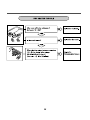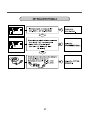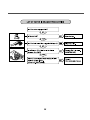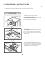
1
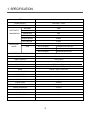
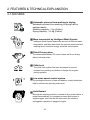
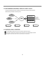
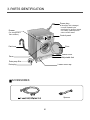
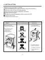
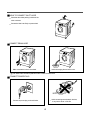
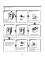
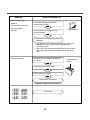
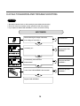
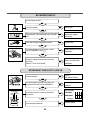
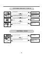
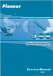
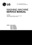
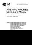
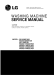
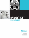
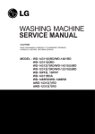
WASHING MACHINE
SERVICE MANUAL
CAUTION
READ THIS MANUAL CAREFULLY TO DIAGNOSE TROUBLES
CORRECTLY BEFORE OFFERING SERVICE.
MODEL : WD-14124(6)RD
WD-12124(6)RD
WD-10124(6)RD
CONTENTS
1. SPECIFICATION............................................................................................................................3
2. FEATURES & TECHNICAL EXPLANATION ................................................................................ 4
3. PARTS IDENTIFICATION ............................................................................................................ 6
4. INSTALLATION ............................................................................................................................. 7
5. OPERATION ................................................................................................................................10
6. WIRING DIAGRAM / PROGRAM CHART ...................................................................................12
7. TROUBLE SHOOTING................................................................................................................13
7-1.BEFORE SVC CHECKING ..................................................................................................13
7-2.QC TEST MODE..................................................................................................................13
7-3.HOW TO KNOW THE WATER LEVEL FREQUENCY.........................................................13
7-4.ERROR DISPLAY ................................................................................................................14
8. ERROR DIAGNOSIS AND CHECK LIST ....................................................................................16
8-1. DIAGNOSIS AND ANSWER FOR ABNORMAL OPERATION ...........................................16
8-2. FAULT DIAGNOSIS AND TROUBLE SHOOTING .............................................................19
9. DISASSEMBLY INSTRUCTIONS ...............................................................................................29
10. EXPLODED VIEW AND PARTS LIST .......................................................................................39
10-1. THE EXPLODED VIEW OF CABINET ASSEMBLY .........................................................39
10-2. THE EXPLODED VIEW OF CONTROL PANEL AND DISPENSER ASSEMBLY ............40
10-3. THE EXPLODED VIEW OF DRUM AND TUB ASSEMBLY .............................................41
10-4. THE EXPLODED VIEW OF DRYER ................................................................................42
APPENDIX (Replacement parts list) ...........................................................................................43
2
1. SPECIFICATION
ITEM
WD-14124(6)RD/WD-12124(6)RD/WD-10124(6)RD
POWER SUPPLY
220V-240V~, 50HZ
PRODUCT WEIGHT
71kg
WASHING
140W
ELECTRICITY
SPIN
300W
CONSUMPTION
FAN MOTOR
25W
DRAIN MOTOR
40W
WASH HEATER
2000W
DRY HEATER
2100W
WASH
45rpm
REVOLUTION
SPEED
SPIN
WD-14124(6)RD
400/800/1000/1400 rpm
WD-12124(6)RD
400/800/1000/1200 rpm
WD-10124(6)RD
400/600/800/1000 rpm
0.3-10kgf/cm2 (30-1000kPa)
OPERATION WATER PRESSURE
CONTROL TYPE
Electronic
WASH CAPACITY
7.0kg (Cotton)
DRY CAPACITY
3.5kg (Cotton)
DIMENSION
600mm(W) 600mm(D) 850mm(H)
WASH PROGRAM
Cotton, Cotton-Eco, Synthetic, Delicate, Wool, Hand Wash, Quick 30
RINSE
Normal / Super / Rinse Hold
DOOR SWITCH TYPE
Manual
WATER LEVEL
8 steps (by sensor)
RESERVATION
From 3 hours to 19 hours
SENSING OF THE LAUNDRY AMOUNT
Adapted
FUZZY LOGIC
Adapted
DISPLAY OF THE REMAINING TIME
Adapted
ERROR DIAGNOSIS
10 items
POWER AUTO OFF
Adapted
CHILD LOCK
Adapted
AUTO RESTART
Adapted
TIME SAVE
Adapted
3
2. FEATURES & TECHNICAL EXPLANATION
2-1.FEATURES
Automatic process from washing to drying.
Automatic process from washing to drying can be
selected easily.
Washing capacity : 7 kg (Cotton)
Drying capacity : 3.5 kg (Cotton)
More economical by Intelligent Wash System
Intelligent Wash System detects the amount of load and water
temperature, and then determines the optimum water level and
washing time to minimize energy and water consumption.
Direct Drive system
The advanced Brushless DC motor rotates the Drum directly
without belt and pulley.
Child-Lock
Wash
Rinse
The Child-Lock system has been developed to prevent
children from pressing any button to change the program
during operation.
Low noise speed control system
By sensing the amount of load and balance, evenly distributes
load to minimize the spinning noise level.
Auto Restart
Although the washing machine is turned off by a power failure, it
restarts automatically in its stopped process when power is
supplied again. And it will be the same when the machine
unplugged in operation is plugged in again.
4
2-2.DETERMINE WASHING TIME BY FUZZY LOGIC
To get the best washing performance optimal time is determined by sensing of water temperature,
selected washing temperature and laundry amount.
water
temperature
washing time
selected
washing
temperature
FUZZY
LOGIC
rinsing time
the best
washing
performance
spin rhythm, time
laundry
amount
SENSING
PROCESSING
DETERMINATION
EFFECT
2-3.WATER LEVEL CONTROL
This model adopts a pressure sensor which can sense the water level in the tub.
Water supply is stopped when the water level to the preset level, then washing program proceeds.
Spinning does not proceed until the water in the tub reduces to a certain level.
5
3. PARTS IDENTIFICATION
Power plug
If the supply cord is damaged,
it must be replaced by the
manufacturer or its service agents
or a similarly qualified person in
order to avoid a hazard.
Drawer
(For detergent and
fabric softener)
Control panel
Drain hose
Door
Lower cover
Adjustable feet
Drum
Drain pump filter
Drain plug
Lower cover cap
ACCESSORIES
Spanner
6
4. INSTALLATION
Before servicing ask troubles of customers
Check the adjustment(power supply is 220-240V~, remove the transit bolts....)
Check the troubles referring to the trouble shooting.
Decide service steps referring to disassembly instructions.
And then, service and repair.
After servicing, operate the appliance whether it works O K or NOT.
STANDARD INSTALLATION
The appliance should be installed as follows.
REMOVE THE TRANSIT
BOLTS
INSTALL THE APPLIANCE
ADJUST THE
ON FLAT AND FIRM SURFACE
HORIZONTAL
Remove the transit bolts
(3EA: )with supplied spanner.
Turn the leveling feet to
set the appliance horizontally.
Keep the transit bolts and
spanner for future use.
Insert the 3 caps
provided into the hole
Low
High
1
The appliance goes up by
rotating the feet clockwise.
2
The appliance come down by
rotating the feet counter
clockwise.
7
HOW TO CONNECT INLET HOSE
Check that the rubber packing is inside of the
valve connector.
Connect the inlet hose firmly to prevent leak.
CONNECT DRAIN HOSE
Make sure that the hose is not twisted.
Avoid submerging the end of the hose.
The drain hose should be placed under 100cm from the floor.
CONNECT POWER PLUG
Avoid connecting several electric devices,
It may be the cause of the fire.
Connect the power plug to the wall outlet.
8
TEST OPERATION
Preparation for
washing.
Connect the power plug to
the outlet.
Connect the inlet hose.
Check the water heating.
Press the POWER button.
Power
Start/Pause
In case of Coloreds program.
Check automatic reverse
turn.
Press the Temp. button
and the present temperature will
be displayed.
Check if the drum rotates
clockwise and counterclockwise.
Check drain and spin
Power off and open the
door
Turn off Wash and Rinse after
pressing the Start/Pause button
and start the machine again.
Check drain and spin.
Press the Start/Pause
button.
Check the water supply.
Check if water is supplied
through the detergent dispenser.
Water removal
Power
Power off and then power on.
Check if the door can be
opened after 3 minutes.
9
If SVC is needed during
check, remove
the remaining water by pulling
out the hose cap.
5. OPERATION
Delay finish
Child lock
• Press the button when reservation washing is
needed.
• When the button is pressed, [
]
is displayed.
A maximum delay of [
] hours
can be set.
• Each press advances time delay by one hour.
• Use ON/OFF button to cancel [Time delay].
• Once Child-Lock is set, and canceled by pressing both
[Wash] and [Rinse] simutaneusly once
Child lock is set. Once Chold Lock is set, all buttons
are iroperable.
• The Child-Lock system can be set at any time even
including during Power-Off, on Pause and operation.
It is automatically cancelled when an operational error
occurs and when the cycle ends.
• When power is off, the LED indicates [
] only.
During operation, or when the programme is paused
the LED will indicate [
] and the remaining time.
Time Delay
Delicate
Synthetic
Wool
Door Lock
Hand
Wash
Cotton
Time Left
Pre
Quick30 Main
Cotton-Eco
Start/Pause
Time Save
Program
Wash
Start/Pause button
Normal
1400
1000
800
400
No Spin
Rinse
Spin
Rinse Hold
Super
95
60
40
30
Cold
Temp.
Time Add
Auto
Big
Small
Dry
Wash program selector
• Use the button to start or pause wash cycle.
•The power turns off automatically in 4 minutes
after the pause button is pressed.
• Press the button to change the program.
10
• 7 programs can be selected depending on the
type of the laundry.
• By turning the dial,
[Cotton
Synthetic
Delicate
Wool
Hand Wash
Quick 30 Cotton-Eco]
can be selected
Time Save
• This option can be
used to reduce the
time of a wash
program.
• This function in not
available with
Quick 30 program.
LED display
• Display the remaining time (Hour : Minute) to finish.
• In case of abnormal operation, error indications are displayed.
(
,
,
,
,
,
,
,
, ,
)
• See trouble shooting guide.
• When drying cycle is completed,
[COOL DOWN] is displayed on
the Multi display.
• The COOL DOWN is setting automatically when a drying cycle is complete.
• When you are not remove a load of clothes from
the dryer as soon as it stops, wrinkles can form.
• The COOL DOWN operating periodically tumbles, rearranges and fluffs
the load to avoid wrinkles without heat for up to 4 hours.
• The
message will continue to display until the clothes are removed
or the START/PAUSE button is pressed.
Door lock display
• It shows whether the door can be opened or not during
the washing.
• If the lamp is off, the door can be opened .
Power
ON/OFF button
Dry selector
• Press the button to turn
power on and off.
• Dry programs can be selected
by pressing the [Dry] button.
• By pressing the button,
[Auto
Big
Time Add
Small ] can be selected.
Water temperature selector
For manual wash, rinse and spin
• Press the button to select water temperature.
• The water temperature is selected
[60°C
95°C
Cold 30°C 40°C]
during cotton program.
• 95°C is selected only for cotton program.
• By pressing the button during operating the
washer, the present temperature is displayed.
• Use these buttons to change washing
method, rinse times, spinning speed.
• When lamp is off, no selection has been
made.
• Prewashing is available for Cotton,
Cotton-Eco, Synthetic program.
11
6. WIRING DIAGRAM / PROGRAM CHART
DISPLAY
PWB
MAIN PWB
NA
123456
123456
VL WH S
/ / K
WH RD Y
WH
123
123
BK RD
/ /
WH WH
RD
123456
123456
WH BK YL
OR BL BN GY PK
RD
213
213
NA
231 4
231 4
BL RD YL
RD
2 4 31
2 4 31
BL RD YL BK
/
WH
3
12
12
BL
2 1
DRY
HEATER
WASHING
HEATER
NOISE
FILTER
WH
BK
BL
THERMOSTAT
NA
PRESSURE
SENSOR
CP
WH
RD
THERMISTOR
THERMISTOR
(Tub)
(Dry Duct Dry H/T)
YL
/
RD
BK RD
BN
/
YL
21
VL 3
654
PIN CONNECTOR NUMBER
WIRE COLOR: BASE/LINE
* Water Supply : WáS
POWER
CORD
Main
Pre
* Intermittent Spin : IáS
* Disentangle : DáT
Rinse
Wash
A
Spin
Extra (Hold)
Normal (Hold)
U
C
14
15
16
18
60
60
60
300 120 360
60
300 120 360
19
20 21
22
23
24 25
DáT
12
W
á
S
Spin
11
I
á
S
Rinse
17
10
W
á
S
Drain
13
9
I
á
S
Drain
8
W
á
S
4
Rinse
7
I
á
S
Drain
6
W
á
S
3
Rinse
5
I
á
S
Drain
4
2
Rinse
3
Drain
2
W
á
S
Drain
E
1
1
Staycooling
Rinse
R
W
á
S
Heat
P
I
á
S
Wash
U
Washing
Drain
E
O
S
W
á
S
Washing
C
E
BK
DOOR LOCK S/W
PROGRAM CHART
T
C
BK
P
RD
321
3 2 1 NA
DRAIN
MOTOR
EARTH TERMINAL
S
P
C
WH
TERMINAL+HOUSING (#250)
L
BN
RD
2 1
2 1 WH
MOTOR
Y
GN
/
YL
GN
/
YL
YL
BK
FAN MOTOR
C
BN
GN
/
YL
(S) (G) (S)
n
WH
123
123
BL YL RD
M P D
A R R
I
N E Y
GND
12
WH 1 2 WH
YL BN BL
/ /
RD YL
U V W
Ha
Hb
23
NA 1
123
12345
12345
RD
3 21
3 21
FUSE
123
123
WH
/RD
WH
BK
BL WH GY YL
/ / / /
RD BK WH BK
INLET
VALVE
WH/RD
SKY BL WH
3 21 1
3 21 1
D
E
T
R
N
O
D
O
Y
F
F
26
27
28
29
60
600 120
Normal
Working
Time
(Hour:Minute)
20 20
Time
(SEC) 120 MIN
Cotton
Cotton-Eco
Synthetic
60
300 120
8
60
8
96
1
8
40
23
60
300 120 360
60
300 120 360
20
20
About 2:41(2:39)
About 3:01
About 1:30
59
Quick 30
About
12
1
Delicate
About 1:01
23
1
HandWash
8
30
About 1:01
29
1
Wool
Wash
MIN 120
About 1:00
29
60
~
96
About 1:03
Rinse
About
39
Rinse Hold
About
39
Dry
About 3:40
About
Spin
Wash
+ Rinse
8
Wash
+Spin
8
60
~
96
60
~
96
About 1:48
About 1:14
Rinse
About
+ Spin
*
*
Basic Cycle
* Basic time is minute in washing chart
Optional Cycle
* The actual program time can be varied with the load amount,
* Pre-Setting Time : Water Supply - 120 sec.
Drain
- 60 sec.
* ~ Time for varies as the temperature or the amount of laundry.
12
water temperature or ambient temperature
12
38
7. TROUBLE SHOOTING
7-1.BEFORE SVC CHECKING
Be careful of electric shock or disconnecting the parts while trouble shooting.
Voltage of each terminal in 220-240V~ and DC while applying an electric current.
7-2.QC TEST MODE.
Pressing Rinse, and Spin button simultaneously.
Power supply ON with pressing upper two button.Then buzzer sound twice.
Press the Start/Pause button as follows.
Press the Start/Pause button more 4 times until stop spinning
Pressing number of
Start/Pause button
Checking Point
Display Status
None
All lamps turn on
1 time
Clockwise spin(right)
Drum rpm(About 40~52)
2 times
Low speed Spin
Drum rpm(About 70~90)
3 times
High speed Spin
Drum rpm(About 90~110)
4 times
Inlet valve for pre-wash operation
Water level frequency(25~65)
5 times
Inlet valve for main-wash operation
Water level frequency(25~65)
6 times
Inlet valve for dry operation
Water level frequency(25~65)
7 times
Counterclockwise spin(left)
Drum rpm(About 40~52)
8 times
Heater is in operation for 3 sec.
Water temperature
9 times
Draining pump operation
Water level frequency
10 times
Dry operation for 6 minutes
Auto off operation after 6 minutes
7-3.HOW TO KNOW THE WATER LEVEL FREQUENCY
Press the Rinse and Spin button simultaneously.
The digits means water level frequency(10-1
ex) 241 : Water level frequency = 241
=24.1
)
10-1
7-4.HOW TO KNOW TO TEMPERATURE OF EACH THERMISTOR
AT OPERATING CONDITION.
■ Thermistor in tub : Press the [WATER TEMP] button.
■ Thermistor in dry duct : Press the [DRY] button.
■ Thermistor in condensing duct : Press the [SPIN] and [DRY] button simultaneously.
13
7-5.ERROR DISPLAY.
If you press the Start/Pause button in error condition, any error except ‘ ’ will disappear and the
machine will change into pause status.
In case of
if the error is not resolved within 20 sec., and in case of other errors,
if the error is not resolved within 4 min., power will be turned off automatically and the error only will be
blinked. But in case of
, power will not be turned off.
ERROR
SYMPTOM
CAUSE
1
WATER INLET
ERROR
• Not reached to the water level(2 level)within 4
minutes after water supplied or not reached to
the preset water level within 25 minutes.
2
DRAIN ERROR
• Not fully drained within 5 minutes.
3
OVERFLOW
ERROR
4
• Water is over flowing(over 8 level).
¡ If
is displayed, drain pump operates to
drain water automatically.
SENSOR PRESSURE
S/W ERROR
• The sensor pressure switch is out of order.
5
DOOR OPEN
ERROR
• In case of operating the reservation function or
the other function with door opened. Close the
door, then the error display is resolved.
• The door switch is out of order.
6
IMBALANCE
ERROR
• The appliance is tilted.
• Laundry is gatherd to one side.
7
HEATING
ERROR
• The THERMISTOR is out of order.
14
ERROR
8
CURRENT
ERROR
SYMPTOM
CAUSE
• MAIN PWB ASSEMBLY is out of order
Replace the MAIN PWB ASSEMBLY
• Winding in the STATOR ASSEMBLY is short-circuited.
Replace the STATOR ASSEMBLY
•“
” is dispplayed during a high spin
Replace the LEAD WIRE ASSEMBLY (MOTOR)
9
MOTOR
ERROR
• The connector in the LEAD WIRE ASSEMBLY is not connected to
the connnector of STATOR ASSEMBLY
Reconnect or repair the connector
• The hall sensor is out of order/defective.
Replace the STATOR ASSEMBLY
10
DRY
HEATOR
ERROR
• The Dry Heater is out of order
Replace the Dry Heater
• The Connector of the Dry Heater is not connected properly to the
connector in the Main PWB ASSEMBLY
Reconnect or repair the connector
• The Dry fan motor is out of order
Replace the fan Motor.
15
8. ERROR DIAGNOSIS AND CHECK LIST
8-1.DIAGNOSIS AND ANSWER FOR ABNORMAL OPERATION
SYMPTOM
NO POWER
GUIDE FOR SERVICE CALL
Is the power plug connected firmly to
220-240V~ outlet?
YES
Power failure? or Breaker opened?
NO
Visit to check
Water inlet trouble
Is "
" displayed?
No Inlet
YES
Is the tap opened?
YES
Is the tap frozen?
NO
Is the water supply shut-off?
NO
Is filter in the inlet valve clogged with
foreign material?
NO
Visit to check
16
Clean the filter of
inlet valve
YES
GUIDE FOR SERVICE CALL
SYMPTOM
• Door does not open
• Error displayed on
the program
Started with door opened?
YES
Close the door
NO
Visit to check
Check if the door switch is O.K.
• DRAIN TROUBLE
Is "
" displayed?
YES
Is the debris filter clogged with foreign
material such as pin, coin and etc.?
NO
Is the drain hose frozen with water,
kinked or crushed?
NO
Visit to check
17
YES
Clean up
the filter.
SYMPTOM
Suds overflow from the
appliance.
GUIDE FOR SERVICE CALL
Is low-sudsing detergent for the drum
washing machine used?
(In this condition, wash and
YES
spin do not operate
normally)
Is the proper amount of detergent used
as recommended?
LOW-SUDSING
YES
Recommend to reduce the using amount
of detergent.
This appliance has the automatic suds sensing function which
operates under much suds condition for good rinse and
preventing overflow.
When much suds are sensed, suds removing function such as
drain, water input and pause will operate without rotating the
drum.
No effect of softener
Is softener put in the correct compartment of
the drawer?
YES
Is the drawer closed during wash?
YES
Is the softener cap clogged?
YES
Explain how to use softener
< Clean the compartment for softener >
Visit to check
18
Compartment for
softener
8-2.FAULT DIAGNOSIS AND TROUBLE SHOOTING
CAUTION
1. Be careful of electric shock or disconnecting the parts while trouble shooting.
2. First of all, check the connection of each part terminal with wiring diagram.
3. If you replace the MAIN PWB ASSEMBLY, Put in the connectors correctly.
NO POWER
When measuring the voltage of the outlet,
is the voltage AC 220-240V~?
NO
Check the fuse?
NO
Replace MAIN PWB
ASSEMBLY
YES
Reconnect the PWB
ASSEMBLY
YES
Reconnect the PWB
ASSEMBLY
YES
Is the led(1) on?
(1)
<PWB ASSEMBLY (MAIN)>
YES
(2)
Is connector(2) disconnected or
disassembled?
<PWB ASSEMBLY (MAIN)>
NO
Is wire of the PWB ASSEMBLY disconnected?
NO
Replace PWB ASSEMBLY
19
NO WATER SUPPLY
Is water supply shut-off?
NO
NO
Open the tap.
When you press both Rinse button and Spin button
simultaneously, is the water level frequency below
240?
YES
Check the AIR CHAMBER
and the tube clogged
with impurity.
Is the inlet valve filter clogged with impurity?
YES
Clean the filter.
Is the tap opened?
YES
NO
NO
Option
Is resistance between each terminal of INLET
VALVE ASSEMBLY is 2~8 k ?
NO
Replace the INLET VALVE
ASSEMBLY.
YES
Check the voltage of the inlet valve connector
220-240V~.
NO
Replace the MAIN PWB
ASSEMBLY
(Refer to 7-2 QC TEST MODE)
DETERGENT DOES NOT FLOW IN
Option
Is water supplied?
NO
Refer to
NO WATER SUPPLY
NO
Check the wiring on the
dispenser.
YES
Wiring diagram
Are replaceptacles correctly connected to the
terminals of the INLET VALVE ASSEMBLY?
YES
SOFTENER
MAIN PRE WASH WASH
Put the detergent in the
correct position
Is detergent put in the correct compartment of
the drawer?
NO
PRE+MAIN
MAIN WASH
YES
MAX
: Detergent
YES
Is the detergent hardened?
20
Clean the drawer.
SOFTENER DOES NOT FLOW IN
Option
Is water supplied?
YES
Wiring diagram
Are receptacles correctly connected to the terminals
of the INLET VALVE ASSEMBLY?
NO
Refer to
NO WATER SUPPLY
NO
Check the wiring on the
dispenser.
NO
Put it in the correct
compartment.
YES
Clean the cap and
drawer.
YES
Fix the bolt tightly.
MAXMAX
YES
Is softener put in the correct compartment of the
max
drawer?
YES
Is the softener cap clogged?
ABNORMAL SOUND
Is the motor bolt loosened?
NO
Is there friction noise from the motor?
21
YES
Replace the STATOR
ASSEMBLY or ROTOR
ASSEMBLY.
HEATING WITHOUT WATER
Wash
Rinse
When pressing Wash and Rinse at the same time
after draining, is the water level frequency 248 ~ 262
or more?
When pressing Rinse, Spin buttons at the same
time while wash, is the water level frequency
between 230 - 243?
NO
Replace the
S.PRESSURE SWITCH
ASSEMBLY
YES
Replace the MAIN PWB
ASSEMBLY
YES
Checking voltage between two pins as press the
POWER button is the voltage 220-240V~?
AC 220V-240V
DRAIN MALFUNCTIONING
Is the drain hose twisted or frozen?
YES
Repair the DRAIN HOSE
ASSEMBLY.
YES
Remove foreign material.
YES
Reconnect or repair the
connector
YES
Repair the DRAIN PUMP
ASSEMBLY.
NO
Is the impeller of the drain pump clogged?
NO
Is the connector disconnected, disassembled?
NO
Is the coil of the drain pump cut-off?
(resistance of coil is 80~150 )
NO
(2)
When checking voltage between connectors
( ,
(1)
PWB ASSY(Main)
)on spinning, is the voltage 220-240V~
as the figure?
22
NO
Repair the MAIN PWB
ASSEMBLY.
HEATING CONTINUOUSLY ABOVE
THE SETTING WATER TEMPERATURE
When checking THERMISTOR on the tub is the
THERMISTOR loosened above 2mm from
the rubber?
23
Push the THERMISTOR
tightly to the rubber.
SPIN TROUBLE
Wash
Rinse
Check on the spinning, is the frequency of the
water level 248 or more. The frequency can be
checked by pressing the Wash and Rinse buttons at
the same time on the program.
NO
YES
Rinse
When pressing Rinse, Spin and POWER buttons at
the same time after power off, press the Start/Pause
button 1 times, is the drum low speed spin?
Spin
Check the S.PRESSURE SWITCH
ASSEMBLY or HOSE (Pressure).
If the problem is on the
S.PRESSURE SWITCH
ASSEMBLY or the HOSE,
replace the S.PRESSURE
SWITCH ASSEMBLY or the
HOSE.
YES
Normal
YES
Correct the connector.
NO
Replace the STATOR
ASSEMBLY
NO
Is it disconnected, or disassembled?
[Red:3pin(1), NA:4pin(2)]
(2)
NO
(1)
Check the motor connector, is the resistance of
the terminal same as the figure?
MOTOR TERMINAL (1)
Resistance of terminal:
(1)
About 5
15
YES
Replace the MAIN PWB ASSEMBLY
DOOR DOES NOT OPEN
Door Lock
Is Door lock Display lamp on?
YES
After draining and
Door lock lamp off,
open the door.
YES
Check switch Assembly,
Door lock connector and
Main PWB
ASSEMBLY(Blue, 3pin)
NO
Is
Displayed?
24
[dHE] ERROR DISPLAY
Dry duct
~
Condensing
duct
Thermistor
Condensing bellows
NO
Replace the thermistor.
(6322FR2046B)
YES
CHECK FOR DRY HEATER TROUBLE
CHECK FOR DRY FAN MOTOR TROUBLE
Disassemble the cabinet cover and
condensing bellows.
Is there any foreign object in condensing
bellows.
NO
Disassemble the dry fan assy and dry duct
upper, and clean foreign object in duct and
fan.
25
YES
Clean the bellows
26
27
28
9. DISASSEMBLY INSTRUCTIONS
ƒR Disassemble and repair the parts after pulling out power cord from the outlet.
CONTROL PANEL
¤ Unscrew the screws on the top plate.
PLATE ASSEMBLY(TOP)
¤Ł The plate assembly(Top) is pulled back and
then upward to arrow direction.
¤ØThe cover(Inner) is disassembled.
¤ The PWB assembly(Display) connectors are
disconnected.
HOOK
¤Ł Pull out drawer, three screws are unscrewed.
¤Ø Push two upper hooks and pull the control
panel forward.
PANEL ASSEMBLY (CONTROL)
¤ The PWB assembly(Display) is disconnected.
PWB ASSEMBLY
(DISPLAY)
¤Ł When 8 screws are unscrewed on the PWB
insulator and the PWB assembly(Display) is
disassembled from the PWB insulator.
29
PWB ASSEMBLY(POWER)
¤ The back cover is removed.
¤ŁTwo screws are unscrewed.
¤ØDisconnect connector from the wiring.
¤ŒPull the PWB assembly (Main) to arrow
direction.
DISPENSER ASSEMBLY
¤ The plate assembly(Top)and the
cover(lnner)are disassembled.
¤ŁPull the drawer to arrow direction.
¤ØTwo screws are unscrewed.
DRAWER
¤ The hose clamps and the hose are
disassembled.
¤ŁThe ventilation bellows are disassembled on
the tub.
DISPENSER ASSEMBLY
30
INLET VALVE
¤ Disconnect the wiring connector.
¤Ł Remove the valve by two screws of the valve
holder.
2
1
ƒTWhen reconnecting the connector
4
3
VALVE ¥L(DRY)
YL/BK - BK
VALVE ¥M(PRE-WASH)
GY/WH - BK
VALVE ¥N (NORMAL-WASH)
VALVE ®È (NORMAL-WASH)
VALVE ¥O (HOT)
WH/BK - BK
BL/RD - BK
BL/RD - BK
COVER LOWER
¤ Remove the lower cover to arrow direction
after one screw is unscrewed.
31
DOOR
¤ Open the door completely.
¤ŁRemove the two screws from the hinge.
¡ When removing the Door Assembly, it is
necessary to hold the Bracket that is inner of
the Cabinet Cover.
Removing method of remained water
¤ Rotate the Cap(Remaining Hose) to arrow
direction.
¤ŁPull it out from hose.
¡ First, prepare a bucket to put in the remained
water.
Cap(Remaining Hose)
32
GASKET ASSEMBLY
¤ The cabinet gasket clamp is released.
¤Ł Two screws are unscrewed from the cabinet
cover.
¤ One screw is unscrewed from the lower cover.
¤Ł The lower cover is disassembled by pulling
out.
¤ØThree screws are unscrewed from the cabinet.
Cap
(Remaining Hose)
¤ The control panel is removed.
¤ŁScrew is unscrewed from the cabinet cover.
33
¤ Remove tub gasket clamp by loosening the
screw.
Tub Gasket
Clamp
¤ Remove dry gasket clamp by loosening the
screw.
Dry
Gasket
Clamp
¤ When reassembling the gasket, put the drain
hole of the gasket downward, then assemble.
Drain Hole
34
ROTOR ASSEMBLY, STATOR ASSEMBLY, FRICTION DAMPER
¤ Remove the back cover.
¤Ł After loosening the bolt, Rotor, pull out the
rotor.
Rotor
Bolt
(ROTOR ASSEMBLY)
¤ Remove the 6 bolt from the stator.
¤ŁDisconnect the 2 connectors.
HOW TO ASSEMBLE THE MOTOR
(STATOR ASSEMBLY)
¤ Remove the bolts at the Tub.
Bolt
¤Ł The Hinge(Damper) at the base is pulled off
pressing on the snaps at the sharp end.
Hinge
(Damper)
¤ØThe hinge at the base is pulled off.
(To arrow direction)
Friction
Damper
(FRICTION DAMPER)
35
PUMP
¤ Remove pump outlet hose.
Pump Outlet Hose
¤ŁRemove tub pump bellows.
¤ØRemove cap(Remaining Hose).
Screw
¤ŒDisconnect the wiring.
¤ºThree screws are unscrewed from the cabinet.
¤ Remove the pump to arrow direction.
Cap
(Remaining Hose)
Tub Pump Bellows
HEATER
¤ Loosen the nut.
¤ŁRemove washing heater by pulling out.
Washing
Heater
Ring Terminal
Nut
CAUTION
When assembling the washing heater, insert
the heater to heater clip on the bottom of tub.
THERMISTOR
¤ Pull it out by holding the thermistor bracket.
ƒT If holding the wire and pulling out it, it may be
broken.
Thermistor
Bracket
Thermistor bulb
36
SWITCH ASSY, DOOR LOCK
¤ The cabinet cover clamp is removed and the
gasket is released.
¤ŁTwo screws are unscrewed.
¤Ø The door lock S/W is disconnected form the
wiring connector and the strap.
WHEN FOREIGN OBJECT STUCK BETWEEN DRUM AND TUB
¤ Remove washing heater.
¤Ł Remove the foreign object(wire,coin,etc) by
inserting long bar in the hole.
Hole
Washing Heater
37
DRY DUCT
¤ Remove 5 screws and dry fan assembly.
Dry fan
Assembly
Dry Duct Upper
¤ŁRemove 6 screws and dry duct upper.
¤ Remove 1 screw and dry heater.
Thermostat
Dry Heater
¤ŁRemove thermostat.
CONDENSING DUCT
¤ Remove 2 screws from cabinet.
¤ Remove clamp and condensing duct.
Condensing Duct
Clamp
Condensing
Bellows
38
10. EXPLODED VIEW AND PART LIST
10-1.THE PART LIST OF CABINET ASSEMBLY
:Non-service part
:Service part
A110
A150
A120
A102
A101
A104
A141
A103
A131
A100
A130
A485
A430
A440
A450
A133
A410
A303
A310
A300
A200
A277
HOT(ORANGE)
COLD(BLUE)
A201
A275
A220
A276
A210
39
10-2 THE EXPLODED VIEW OF CONTROL PANEL &
DISPENSER ASSEMBLY
:Non-service part
:Service part
F170
F300
F160
F460
F461
F310
F430
K343
F450
F220
F120
F110
F210
F130
40
10-3 THE EXPLODED VIEW OF DRUM & TUB ASSEMBLY
:Non-service part
:Service part
K140
K141
K110 K142 K411 K420
K123
K120
K360
K211
K130
K143
K131
K350
K513
F140
K310
K511
K510
K610
K105
K611
K410
K100
K320
K530
K343
K341
K344
K340
K531
K520
41
K540
10-4 THE EXPLODED VIEW OF DRYER
:Non-service part
:Service part
M120
M110
M100
M121
M210
M101
M220
M312
M310
M311
M230
42
MAY. 2002 PRINTED IN KOREA
P/No.:3828ER3013K