1
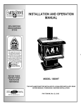
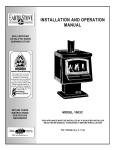
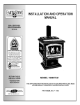
INSTALLATION AND OPERATION
MANUAL
EPA CERTIFIED
WOOD BURNING
STOVE
P
RETAIN THESE
INSTRUCTIONS
FOR FUTURE
REFERENCE
MODEL 1400HT
THIS APPLIANCE MUST BE INSTALLED BY A QUALIFIED INSTALLER.
READ ENTIRE MANUAL THOROUGHLY BEFORE INSTALLATION.
P/N 775000M, Rev. G, 12/03
IMPORTANT WARNINGS
CAUTION: PLEASE READ THIS ENTIRE MANUAL BEFORE YOU INSTALL AND USE YOUR NEW ROOM
HEATER. FOR YOUR SAFETY, FOLLOW THE INSTALLATION, OPERATION AND MAINTENANCE INSTRUCTIONS EXACTLY, WITHOUT DEVIATION. FAILURE TO FOLLOW THESE INSTRUCTIONS MAY RESULT IN
PROPERTY DAMAGE, BODILY INJURY, OR EVEN DEATH. IF THIS APPLIANCE IS NOT PROPERLY INSTALLED,
A HOUSE FIRE MAY RESULT. CONTACT YOUR LOCAL BUILDING OR FIRE OFFICIALS ABOUT RESTRICTIONS
AND INSTALLATION INSPECTION REQUIREMENTS IN YOUR AREA.
1. If utilizing an older chimney, it must be inspected for adequate serviceability. Refer to the
heading Chimney Inspection on page 8 of this
manual.
2. The minimum clearances must be maintained
for all combustible surfaces and materials including; furniture, carpet, drapes, clothing,
wood, papers, etc. Do not store firewood within
this clearance space. Failure to maintain clearances to all combustibles may result in a house
fire.
3. This appliance requires non-combustible floor
protection as outlined in this manual (see Floor
Protection on page 6 for additional information).
4. Minimum ceiling height must be 7 feet (213 cm)
(measured from base of appliance to ceiling).
5. DO NOT CONNECT THIS UNIT TO A CHIMNEY
FLUE CONNECTED TO ANOTHER APPLIANCE.
6. Do not connect this appliance to air ducts or
any air distribution system.
7. PREVENT CREOSOTE FIRE: Inspect and clean
chimney frequently. Under certain conditions of
use, creosote buildup may occur rapidly. Inspect chimney connector and chimney twice
monthly and clean if necessary. Using green or
inadequately seasoned wood can greatly increase creosote buildup. Use dry wood to minimize creosote buildup.
8. USE SOLID WOOD FUEL ONLY: This appliance
is approved for burning dry seasoned natural
wood only. CAUTION: BURN UNTREATED
WOOD ONLY. DO NOT BURN GARBAGE OR
FLAMMABLE FLUIDS SUCH AS GASOLINE,
NAPHTHA OR ENGINE OIL.
9. Never use gasoline, gasoline-type lantern fuel,
kerosene, charcoal lighter fluid, or similar liquids to start or "freshen up" a fire in this heater.
Keep all such liquids well away from the heater
while it is in use.
10. DO NOT OVERFIRE: If heater or chimney connector glows, you are overfiring. Overfiring this
appliance could cause a house fire. Overfiring is
11.
12.
13.
14.
15.
16.
17.
18.
19.
PAGE 2
a condition where the appliance is operated at
temperatures above its design capabilities.
Overfiring can be caused by improper installation, improper operation, lack of maintenance or
improper fuel usage. Damage caused from overfiring is NOT covered under the manufacturer’s
limited warranty.
NEVER LEAVE AN UNATTENDED STOVE
BURNING ON HIGH. Operation of the stove with
the primary air control at its highest burn rate
setting for extended periods can cause dangerous overfiring conditions. The primary air control should only be positioned at the highest
setting during start-up procedures and for short
durations. When leaving the stove unattended
ensure that the primary air control is set to the
low or medium low range.
Use a metal container with a tight fitting lid to
dispose of ashes.
IN THE EVENT OF A COMPONENT FAILURE,
USE ONLY COMPONENTS PROVIDED BY THE
MANUFACTURER AS REPLACEMENT PARTS.
Burning any kind of fuel uses oxygen from the
dwelling. Be sure that you allow an adequate
source of fresh air into the room where the
stove is operating (see Ventilation and Outside
Air on page 6).
CAUTION: HOT WHILE IN OPERATION. An appliance hot enough to warm your home can severely burn anyone touching it. Keep children,
clothing and furniture away. Contact may cause
skin burns. Do not let children touch the appliance. Train them to stay a safe distance from
the unit.
Do not operate this appliance without the firebox baffle brick properly installed.
Build fires directly upon the brick hearth inside
the stove. Do not use grates, irons or any other
method to elevate the fire.
SAVE THESE INSTRUCTIONS.
See the listing label located on the back of
stove (or see Safety/Listing Label on page 22).
TABLE OF CONTENTS
Important Warnings ................................................ 2
CONGRATULATIONS ON THE PURCHASE OF
YOUR NEW WOODSTOVE MANUFACTURED BY
LENNOX HEARTH PRODUCTS.
Testing/Listing, EPA, Using this Manual.................. 3
Planning Your Installation ..................................... 4-6
When you purchased your new woodstove, you
joined the ranks of thousands of concerned individuals whose answer to their home heating needs
reflects their concern for aesthetics, efficiency and
our environment. We extend our continued support
to help you achieve the maximum benefit and enjoyment available from your new wood stove.
Manufactured (Mobile) Home Requirements ...........6
Installation .......................................................... 7-11
Product Features and Controls ..............................12
Care and Operation .......................................... 12-13
It is our goal at Lennox Hearth Products to provide
you, our valued customer, with an appliance that
will ensure you years of trouble free warmth and
pleasure.
Recommended Fuel ...............................................14
Maintenance ..................................................... 14-15
Troubleshooting ................................................ 16-17
Thank you for selecting a Lennox Hearth Products
stove as the answer to your home heating needs.
Specifications..........................................................18
Replacement Parts List..................................... 19-20
Sincerely,
All of us at Lennox Hearth Products
Optional Accessories ............................................. 21
Safety/Listing Label ............................................... 22
EPA Label … ......................................................... 23
Ownership Records ............................................... 24
TESTING/LISTING
Model 1400HT has been tested to UL Standards 1482
and ULC-S627 for installation in residential and manufactured (mobile) home construction. The listing laboratory is OMNI Test Laboratories Inc, Beaverton, Oregon,
Report #030-S-03-02.
EPA CERTIFICATION
This stove has been tested to rigorous emissions standard, and has been certified by the Environmental Protection Agency.
PACKAGING LIST
This appliance is packaged with an accessory package,
which contains the following:
One - Installation and operation instructions
manual.
One - Warranty.
Five - Baffle brick.
USING THIS MANUAL
Please read and carefully follow all of the instructions
found in this manual. Please pay special attention to the
safety instructions provided in this manual. The Homeowner’s Care and Operation Instructions included here
will assure you have many years of dependable and
enjoyable service from your appliance.
PAGE 3
PLANNING YOUR INSTALLATION
QUESTIONS TO ASK LOCAL BUILDING OFFICIAL
A correct installation is critical and imperative for reducing fire hazards and perilous conditions that can arise
when wood burning appliances are improperly installed.
The installer must follow all of the manufacturer’s instructions.
The installation of a wood burning appliance must conform to local codes and applicable state and federal
requirements. Familiarity with these requirements before installation is essential. Important considerations to
discuss with local building officials include:
1. Applicable codes (i.e. Uniform Mechanical Code,
State or Regional Codes)?
Electrical codes: Optional Blower Assemblies have
a flexible electrical cord that must be electrically
grounded per local codes or per electrical codes:
In USA, NEC, ANSI/NFPA 70-1987
In Canada, CSA C22.1
WARNING: ELECTRICAL GROUNDING INSTRUCTIONS: THIS APPLIANCE IS EQUIPPED WITH A
THREE-PRONG (GROUNDING) PLUG FOR YOUR
PROTECTION AGAINST SHOCK HAZARD AND
SHOULD BE PLUGGED DIRECTLY INTO A PROPERLY GROUNDED THREE-PRONG RECEPTACLE.
DO NOT CUT OR REMOVE THE GROUNDING
PRONG FROM THIS PLUG.
DO NOT ROUTE POWER CORD UNDER OR IN
FRONT OF APPLIANCE.
2. Local amendments?
3. Is a permit required - cost? (You may wish to contact your insurance company to ask if they require
this).
4. Is outside combustion air required?
5. Rooms where the installation is not allowed?
SMOKE DETECTORS
Since there are always several potential sources of fire
in any home, we recommend installing smoke detectors. If possible, install the smoke detector in a hallway
adjacent to the room (to reduce the possibility of occasional false activation from the heat produced by the
stove). If your local code requires a smoke detector be
installed within the same room, you must follow the requirements of your local code. Check with your local
building department for requirements in your area.
NOTE – This appliance is NOT approved for installation into a Manufactured (Mobile) Home in Canada
SELECTING A LOCATION
The design of your home and where you place your
stove will determine its value as a source of heat. A
wood stove depends primarily on air circulation (convection) to disperse its heat, and therefore, a central
location is often best. There are other practical considerations, which must be considered before a final selection of locations is made.
♦
♦
♦
♦
♦
♦
♦
Existing Chimneys
Wood Storage
Aesthetic Considerations
Roof Design (Rafter Locations & Roof Pitch)
Room Traffic
Proximity to Combustibles
Electrical Wiring
The installation of this stove will require some research.
Once your options are determined, consult with your
local building department who will be able to give you
the necessary installation requirements for your area (Is
a building permit required, Rooms where installation
may not be allowed, etc.).
WARNING: CHECK ALL LOCAL BUILDING AND
SAFETY CODES BEFORE INSTALLATION. THE INSTALLATION INSTRUCTIONS AND APPROPRIATE
CODE REQUIREMENTS MUST BE FOLLOWED EXACTLY AND WITHOUT COMPROMISE. ALTERATIONS TO THE STOVE ARE NOT ALLOWED. DO
NOT CONNECT THE STOVE TO A CHIMNEY SYSTEM SERVING ANOTHER STOVE, APPLIANCE, OR
ANY AIR DISTRIBUTION DUCT. FAILURE TO FOLLOW THESE INSTRUCTIONS WILL VOID THE
MANUFACTURER’S WARRANTY.
If you plan to vent your stove into an existing masonry
chimney, have it inspected by a local fire marshal or
qualified installer. Remember that a stove's performance is heavily influenced by the chimney and its location on the roof. An oversized flue may not provide effective draw, and a flue liner may be required (see Draft
Requirements on page 9). Consult your dealer or qualified installer before final selection is made.
This stove requires pre-installation work to be completed before installation can take place. This will include the preparation of the floor and appropriate
hearth pad for acceptance of outside air (if applicable),
and for modification for flue and chimney.
PAGE 4
PLANNING YOUR INSTALLATION
COMBUSTIBLE WALL CLEARANCE
WARNING: IT IS VERY IMPORTANT THAT YOU OBSERVE THE MINIMUM CLEARANCES.
There are listed clearances for your stove which were
determined in a Laboratory test using various "classes"
of stove pipe or chimney. Minimums are first established for the stove itself and increased based on how
much heat is transferred by each class of pipe.
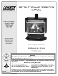
*ALCOVE CLEARANCE
Required pipe: Type L-Vent pipe to top of stove. Approved brands are Dura-Vent, Pro-Vent, Ameri-I-Tek,
Standex, and Metal Bestos.
Alcoves must have minimum dimensions of 84" (213
cm) height minimum, 46" (117 cm) width minimum and
24" (610 mm) depth maximum.
Note: Manufactured (mobile) home installations require
the use of a Type L Vent Chimney connector only. Use
of a single wall flue pipe connection is not permitted.
Residential Reduced Clearance
Using Listed L-Vent pipe (double wall air insulated) to
the top of the stove. Approved brands are: JakesEvans, Dura-Vent, Security, Pro-Vent, Ameri-Tek, Metal
Bestos.
Clearances (inches / millimeters)
A. 10 ½ / 267
C. 15 / 381
E. 9 ½ / 241
B. 20 / 508
D. 8 / 203
F. 5 / 127
Residential Standard (not approved for manufactured [mobile] homes)
Using single wall pipe connector to the top of the stove.
Clearances (inches / millimeters)
A. 15 / 381
C. 15 / 381
E. 8 ½ / 216
B. 19 / 483
D. 13 / 330
F. 5 / 127
Manufactured (Mobile) Home Standard Clearance
Using Approved L-Vent only. Approved brands are
Dura-Vent, Security, Pro-Vent, and Ameri-Tek. Manufactured (Mobile) Home installations must use a rain
cap with a spark arrester.
Clearances (inches / millimeters)
A. 10 ½ / 267
C. 15 / 381
E. 9 ½ / 241
B. 20 / 508
D. 8 / 203
F. 5 / 127
ALCOVE CLEARANCES:
Back wall to pipe O.D.
10 1/2" (267 mm) Minimum
Side wall to pipe O.D.
20" (508 mm) Minimum
Back wall to stove
8" (203 mm) Minimum
Side wall to stove
9 1/2" (241 mm) Minimum
* NOTE: Alcove dimensions cannot be reduced by the
use of non-combustible materials such as brick,
stone, etc. Alcove dimensions listed are minimum
dimensions and are not measurements for building
an Alcove. You will need to consider these clearances, as well as other dimensional requirements
before you build the alcove and install this appliance.
OPTIONAL ARCH TREATMENT
An alcove depth of 24" (610 mm) (or less) will allow for
a minimum height of 84" (213 cm) and may be trimmed
with a 2 1/4" (57 mm) maximum arch treatment if desired.
CORNER
INSTALLATION
PARALLEL
INSTALLATION
PAGE 5
PLANNING YOUR INSTALLATION
REDUCED MASONRY STRUCTURE CLEARANCE
(ALCOVE)
Your Earth Stove can be installed in a masonry structure with reduced clearances if the structure was built to
National Building Code for fireplaces and chimneys
(UBC 37).
The firebox of the masonry structure must be of adequate size to allow a minimum of 6" (152 mm) clearance to the sides and top of the stove and 2" (51 mm)
clearance to the rear. All stove models must be installed
on their original listed legs or base unless otherwise
specified by OMNI Testing Laboratory.
PROTECTED WALL CLEARANCE
Some local codes will allow reduced clearances when the
stove is installed adjacent to a protected wall system. The
variance must be approved by your local building official.
Normally, the protected wall system is defined as a noncombustible material with a minimum of 1" (25.4 mm) air
space behind. Check your local building codes or with a
qualified installer (Ref. NFPA 211).
OUTSIDE AIR
In all manufactured (mobile) homes and in many site built
residences (subject to local code), a stove may be required
to use outside air for combustion. A 3” (76 mm) diameter
outside air floor duct is available through your dealer.
FLOOR PROTECTION
This appliance requires a non-combustible floor protection for
ember protection. If the floor protection is to be stone, tile,
brick, etc., it must be mortared or grouted to form a continuous non-combustible surface. If a chimney connector extends horizontally over the floor, protection must cover the
floor under the connector and at least 2" (51 mm) to either
side.
The floor protection must extend completely beneath the
stove and to the front, sides, and rear as indicated:
USA Requirements
16” (406 mm) min. to the front of the fuel door glass
8” (203 mm) min. beyond the sides of the fuel door opening
Canada Requirements
18” (457 mm) min. to the front of the fuel door glass
8” (203 mm) min. beyond the sides of the stove body
This appliance utilizes a 3" (76 mm) diameter outside air
floor duct (Catalog # 14M66). Outside air can be taken from
beneath the home or through an outside wall. The collar for
connecting flex to stove in on the underside of the stove as
shown here.
STANDARD PARALLEL HEARTH PAD SHOWN
0” - USA
8” – Can.
8” (203 mm)
Canada
8” (203 mm)
Canada
8” - USA
8” - USA
18” (457 mm) – Canada
16” (406 mm) - USA
PAGE 6
INSTALLATION
MANUFACTURED (MOBILE) HOME REQUIREMENTS
This stove is certified as a Room Heater, Solid Fuel Type
and may be used in Manufactured Housing providing the
following requirements are followed:
• An outside air inlet must be provided for combustion and
be unrestricted while unit is in use.
• WARNING: DO NOT INSTALL APPLIANCE IN A
SLEEPING ROOM.
• CAUTION: THE STRUCTURAL INTEGRITY OF THE
MOBILE HOME FLOOR, WALL, AND CEILING/ROOF
MUST BE MAINTAINED.
• Regulations require that the appliance must be secured to
the floor and grounded to the chassis. See Securing the
Stove to the Floor (and) Grounding Stove below.
• Required venting is 6” (152 mm) diameter Type L-Vent
connector pipe with listed factory-built 103HT chimney suitable for use with solid fuels or a code approved masonry
chimney. Approved brands of factory built chimney are listed
in this manual. A rain cap and spark arrestor are required
(see Clearances, page 5).
• The chimney must provide for a section joint so that any
parts extending above 13' 6" (343 mm) from ground level can
be removed for transportation of the mobile dwelling.
from the stove to the chassis of the manufactured (mobile)
home.
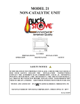
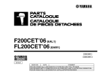
INSTALLING THE BAFFLE BRICKS
There are 2 brick retainer tube assemblies located
below the ceiling of the firebox which require baffle
brick before the stove can be operated. Install the
baffle brick as follows:
1. Place the first three brick onto the brick retainers
with the notch facing up and toward the front.
Next, slide the three brick all the way to the right
(as you face the stove. See top view illustration
below).
2. Place the fourth brick on top of the three brick.
Position it so the notch is facing up and pointing
to the left.
3. Install the fifth brick and slide all the way to the left.
4. Rotate the fourth brick into position (notch to the
front and facing up) until it drops into place.
IMPORTANT: The baffle brick requires periodic inspection and replacement for proper operation. If the baffle
bricks are fractured or crumbling, they should be replaced. Do not operate this appliance without the baffle
brick properly installed.
SECURING THE STOVE TO THE FLOOR
Manufactured (Mobile) Homes Only
Once the outside air floor duct is in position, replace the floor
protector. Make sure that the floor protector's hole is aligned
with the outside air opening. Next position and align the stove
on the hearth pad. Manufactured (Mobile) home installations
require that the stove be secured to the floor.
This ensures that the stove will not shift when the manufactured (mobile) home is moved. To do this, mark where the
holes are to be drilled using a marking instrument long
enough and small enough to fit through the (4) four holes in
the stove legs. Mark holes, then remove the stove. Drill the
(4) four holes, with a 1/4" (7 mm) drill bit. Drill down through
the floor protector and the manufactured (mobile) home floor.
Use 1/4" (7 mm) lag bolts and secure to the manufactured
(mobile) home floor.
NOTE: If the composition of the manufactured (mobile) home
floor is of light particleboard construction, you will be required
to secure the stove with regular hex head bolts and nuts.
This will ensure that the bolts will not rip out of the floor when
the manufactured (mobile) home is being moved.
GROUNDING STOVE
Manufactured (Mobile) Homes Only
Regulations require that all stoves installed in manufactured
(mobile) homes must be grounded. To do this simply attach
a piece of No. 8 copper wire, at least 18" (457 mm) in length
PAGE 7
Installing Baffle Brick
Right
Left
Top View of Baffle Brick Installed
Side View of Baffle Brick Installed
Brick Retainer / Tube Assembly
INSTALLATION
TYPES OF CHIMNEYS
The chimney is a vital part of your stove installation. A
properly built masonry chimney or a properly installed
factory built chimney will assure a consistent draft under
a variety of weather conditions (a smoking stove is usually caused by a chimney problem). The stove flue size
is 6 (152 mm) inches diameter, which is approximately
28 square inches (711 square mm) minimum. The
maximum flue size should be no more than (3)-three
times the cross sectional area of the size of the stove
flue collar. In this case, that would be no larger than a
10-inch (254 mm) diameter stack, or approximately 85
square inches (216 square cm) maximum.
All chimneys must be installed as specified by local
building codes and according to the chimney manufacturer instructions (in the case of a factory built chimney).
See the chimney manufacturer instructions for exact
specifications. Factory built chimneys must comply with
UL 103HT or ULC S629.
Connection To A Factory Built Chimney: This space
heater is to be connected to a factory-built chimney
conforming to CAN / ULC – S629, Standard for 650°C
Factory-Built Chimneys.
For Reduced Residential Clearances: Type L and
listed double wall connector pipe is acceptable. Install
any factory built brand of pipe according to the manufacturer's instructions.
Vapor Barrier at Chimney Penetration
Install all venting components per the Vent Manufacturer’s installation instructions. Ensure that there is an
effective vapor barrier at the location where the chimney penetrates to the exterior of the structure. This can
be accomplished by applying a non-hardening waterproof sealant to the following components:
•
•
Factory
Built
Chimney
•
•
Around the chimney at the point where the storm
collar will meet the chimney just above the Flashing.
Along the vertical seam of the chimney pipe, where
it is exposed to the weather.
On each nail head on the flashing.
Around the chimney at the point where the storm
collar will meet the chimney just above the flashing.
Notes:
• On a flat or tarred and graveled roofs, nail and seal
the flat roof flashing to the roof on all sides with
roofing compound.
• Do not put screws through the flashing into the
chimney pipe.
Tile-lined
Masonry
Chimney
ACCEPTABLE CONNECTOR PIPE FOR INSTALLATIONS
For Standard Residential Clearances: Six (6) inch
(152 mm) minimum, single wall, 25 gage minimum
thickness, stove pipe is acceptable. Three (3) predrilled holes are provided in the flue collar for fastening
the pipe securely to the stove. Use sheet metal screws
to do this.
Additional sections of single wall pipe
should be fastened together with at least three (3) sheet
metal screws each section. When connecting to the
factory built ceiling support package, use the manufacturer's transition piece, usually called a dripless connector, to join single wall pipe to their factory built chimney
section.
Minimum Flue Size: The required minimum diameter
and area required for the flue size is (respectively) 6
inches / 152 mm diameter, which is approximately 28
square inches / 711 square mm. The maximum flue
size should be no more than (3) three times the cross
sectional area of the size of the 6 inches / 152 mm diameter flue collar. In this case, that would be no larger
than a 10 inch (254 mm) diameter (area = approx. 85
sq. inches [216 sq. cm]).
CHIMNEY INSPECTION
Existing chimneys must be inspected before installing
your stove. Consult your local building department for
chimney code requirements. A masonry chimney must
have a code approved liner. This liner must not have
broken or missing pieces. Some non-code masonry
chimneys may be brought up to code by being relined.
(Consult your dealer or qualified chimney sweep). Factory built chimneys should also be inspected, first for
creosote deposits (which should be removed), and then
for integrity of the stainless steel liner. Look for obvious
bulges in the lining which may indicate the need to replace that section (use a bright flashlight). Also, inspect
the attic to see that the chimney has proper clearance
to combustible framing members. For interior masonry
chimneys and most factory built chimneys, this must be
a (2) two inch (51 mm) air space clearance, which must
not be filled with insulation or any other material. An
exterior masonry chimney must have a (1) one-inch
(25.4 mm) air space clearance.
PAGE 8
INSTALLATION
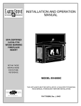
CHIMNEY HEIGHT REQUIREMENTS
The chimney must extend 3 feet (914 mm) above the level
of roof penetration and a minimum of 2 feet (610 mm)
higher than any roof surface within 10 feet (305 cm) (see
below). Check with your local building officials for any additional requirements for your area.
Due to prevailing winds, local terrain, adjacent tall trees, a
hill, or ravine near the home, or adjacent structures, additional chimney height or a special chimney cap may be
required to ensure optimum performance.
The 2’ by 10’ Rule for Vent Termination
3’ (915mm)
Requires A Listed
Termination Cap
2’ (610mm)
10’ (305 cm)
The top of the flue must be 2’ (610 mm)
higher than any part of the roof within
10’ (305 cm) horizontal and a minimum of
3’ (915 mm) higher than the highest point of
roof penetration.
For Manufactured (Mobile) Homes Only: Portions of
the chimney and termination that exceed an elevation of
13½ feet above ground level may be designed to be
removed for transporting the manufactured (mobile)
home.
PAGE 9
INSTALLATION
DRAFT REQUIREMENTS
The appliance is merely one component of a larger system. The other equally important component is the venting system which is necessary for achieving the required flow of combustion air to the fire chamber and for
safely removing unwanted combustion byproducts from
the appliance. If the venting system's design does not
promote these ends, the system may not function properly. Poorly functioning venting systems may create
performance problems (i.e. smoking stove, poor heat
output, fire goes out, window blackens, increased creosote buildup, etc.) as well as be a safety hazard. Some
factors that may lead to performance problems are as
follows:
•
•
•
•
•
•
•
•
•
Oversized or undersized chimney.
Excessive offsets in venting.
Insufficient vertical height of chimney.
Insufficient chimney termination height in relationship to roof.
Insufficient ventilation.
Lack of maintenance.
Improper operation.
Burning improper fuel (unit is approved for use with
natural dry well-seasoned wood only).
Down drafts in the chimney (may need a special wind
cap).
To ensure that the venting system is functioning properly a draft test should be performed (see Draft Test
Procedure on this page).
American National Standards Institute ANSI/NFPA 21192: A chimney or vent shall be so designed and constructed to develop a flow sufficient to completely remove all flue and vent gases to the outside atmosphere.
The venting system shall satisfy the draft requirements
of the connected appliance in accordance with the
manufacturer instructions.
DRAFT TEST PROCEDURE
After this appliance is installed a draft test should be
performed to ensure proper draft. A qualified technician
should perform the draft test procedure as follows:
5) After the fire is well established (20-25 minutes)
and burning at a low setting, perform the draft test
per the gauge manufacturer instructions. The draft
gauge should read between .05 and .07” W.C. (inches
water column). Excessive draft (above .07 W.C.I.) can
result in too much combustion air to be pulled into the
firebox, this will produce hotter burns and could result in
overfiring. Too little draft (below .05” W.C.) will not allow
enough combustion air delivery to maintain a fire well or
cause performance problems such as smoking (this
may result in improper operation of appliance, i.e. will
not maintain fire well unless fuel door is left open).
6) Install a screw to seal the draft test port in the vent pipe.
If the draft test reading was not within the required
range, correct the installation and repeat this procedure.
VENTILATION REQUIREMENTS / PROVIDE ADEQUATE AIR FOR COMBUSTION
THE FRESH AIR REQUIREMENTS OF THIS APPLIANCE MUST BE MET WITHIN THE SPACE WHERE
IT WILL BE INSTALLED. VENTILATION IS ESSENTIAL WHEN USING A SOLID FUEL BURNING
HEATER.
In well insulated and weather tight homes, it may be
difficult to establish a good draft up the chimney
(caused by a shortage of air in the home). The lack of
air is caused by many common household appliances
which exhaust air from the home (such as a furnace,
heat pump, air conditioner, clothes dryer, exhaust fans,
fireplaces, and other fuel burning appliances). Also, the
combustion process of this heater uses oxygen from
inside the dwelling. If the available fresh air delivery in
the dwelling is insufficient to support the demands of
these appliances, problems can result (i.e. excessive
negative pressure can develop in the dwelling which will
affect the rate at which this appliance can draft thus
resulting in performance problems; See Draft Requirements on this page). To correct this problem it may help
to open a window (preferably on the windward side of
the house) or install a vent to provide make-up air into
the dwelling.
1) Close all windows and doors in the dwelling.
2) Turn on or operate all appliances which remove air
from the home (such as a furnace, heat pump, air
conditioner, clothes dryer, exhaust fans, fireplaces,
and other fuel burning appliances).
3) Drill a hole in the vent pipe per the draft gauge
manufacturers instructions (to create a draft test
port). Note: Hole location should be a minimum of 1
foot above flue outlet collar.
4) Start a fire (See How To Start And Maintain A Fire
on page 16).
PAGE 10
INSTALLATION
See Pipe Manufacturers Instructions For Installation Requirements Of Venting Components And Vent Clearances.
RESIDENTIAL STANDARD
Using 6” (152 mm) Diameter Single Wall Connector Pipe. Not Approved For Manufactured
(Mobile) Homes.
MANUFACTURED (MOBILE) HOME STANDARD
Using 6” (152 mm) Diameter Type L-Vent Connector Pipe
IMPORTANT NOTES:
•
Minimize the use of elbows (30°, 45° or 90°) - Offsets in the venting
system are very restrictive and will inhibit the draft (i.e. You will
lose approximately 5 feet of effective draft for every 90 degrees of
direction change). This appliance requires 12 to 15 feet of effective
draft for optimum performance (see Draft Requirements on
page 10).
•
First section of pipe must be vertical - Use as much straight vertical pipe directly above the appliance as possible before using an
elbow (a 2’ to 3’ initial vertical rise is suggested).
PAGE 11
INSTALLATION - Combustible Wall Chimney Connector Pass-Throughs
A
Chimney Flue
Min. Chimney Clearance to Brick &
Combustibles – 2 in. (50.8mm)
Min. 12 in.
(304.8mm)
to Combustibles
B
Min. Clearance 12 in.
(304.8mm) of Brick
Chimney
Connector
Fire Clay
Liner
Min. Chimney Clearance from Masonry to Sheet Steel
Supports & Combustibles – 2 in. (50.8mm)
Nonsoluble
Refractory
Cement
Min. Clearance
9 in. (228.6mm)
Factory Built
Chimney Length
Chimney Length
Flush with Inside of Flue
Chimney
Connector
Chimney
Flue
Use Chimney
Mfrs. Parts to
Attach Connector Securely
Air Space – 9 in.
(228.6mm) Min.
Solid-Insulated
Masonry
Listed FactoryChimney
Built Chimney
Sheet Steel Supports Length
C
Min. Chimney Clearance from Masonry to Sheet Steel
Supports & Combustibles – 2 in. (50.8mm)
2 Ventilated Air
Channels, Each
1 in. (25.4 mm)
Construction of
Sheet Steel
D
Chimney Flue
2 Air Channels, Each 1
in. (25.4 mm)
Chimney
Connector
Min. 6 in.
(152.4mm) glass
Fiber Insulation
Masonry Sheet Steel Supports
Chimney
Min. Chimney Clearance
from Masonry to Sheet
Steel Supports & Combustibles – 2 in.
Min. Clearance
(50 8
)
Sheet Steel
2 in. (50.8 mm)
Supports
1 in. (25.4 mm)
Air Space to
Chimney
Chimney
Section
Length
Chimney
Connector
Air Space – 2 in.
(50.8mm) Min.
Masonry
Chimney
Chimney
Connector
Chimney
Sheet Length
Steel
Supports
Method A. 12” (304.8 mm) Clearance to Combustible Wall
Member: Using a minimum thickness 3.5” (89 mm) brick and a
5/8” (15.9 mm) minimum wall thickness clay liner, construct a wall
pass-through. The clay liner must conform to ASTM C315 (Standard Specification for Clay Fire Linings) or its equivalent. Keep a
minimum of 12” (304.8 mm) of brick masonry between the clay
liner and wall combustibles. The clay liner shall run from the brick
masonry outer surface to the inner surface of the chimney flue
liner but not past the inner surface. Firmly grout or cement the
clay liner in place to the chimney flue liner.
Method B. 9” (228.6 mm) Clearance to Combustible Wall Member: Using a 6” (152.4 mm) inside diameter, listed, factory-built
Solid-Pak chimney section with insulation of 1” (25.4 mm) or more,
build a wall pass-through with a minimum 9” (228.6 mm) air space
between the outer wall of the chimney length and wall combustibles. Use sheet metal supports fastened securely to wall surfaces
on all sides, to maintain the 9” (228.6 mm) air space. When fastening supports to chimney length, do not penetrate the chimney
liner (the inside wall of the Solid-Pak chimney). The inner end of
the Solid-Pak chimney section shall be flush with the inside of the
masonry chimney flue, and sealed with a non-water soluble refractory cement. Use this cement to also seal to the brick masonry
penetration.
Method C. 6” (152.4 mm) Clearance to Combustible Wall
Member: Starting with a minimum 24 gage (.024” [.61 mm]) 6”
(152.4 mm) metal chimney connector, and a minimum 24 gage
ventilated wall thimble which has two air channels of 1” (25.4 mm)
each, construct a wall pass-through. There shall be a minimum 6”
(152.4) mm separation area containing fiberglass insulation, from
the outer surface of the wall thimble to wall combustibles. Support
the wall thimble, and cover its opening with a 24-gage minimum
sheet metal support. Maintain the 6” (152.4 mm) space. There
should also be a support sized to fit and hold the metal chimney
connector. See that the supports are fastened securely to wall
surfaces on all sides. Make sure fasteners used to secure the
metal chimney connector do not penetrate chimney flue liner.
Method D. 2” (50.8 mm) Clearance to Combustible Wall Member: Start with a solid-pak listed factory built chimney section at
least 12” (304 mm) long, with insulation of 1” (25.4 mm) or more,
and an inside diameter of 8” (2 inches [51 mm] larger than the 6”
[152.4 mm] chimney connector). Use this as a pass-through for a
minimum 24-gage single wall steel chimney connector. Keep
solid-pak section concentric with and spaced 1” (25.4 mm) off the
chimney connector by way of sheet metal support plates at both
ends of chimney section. Cover opening with and support chimney section on both sides with 24 gage minimum sheet metal supports. See that the supports are fastened securely to wall surfaces
on all sides. Make sure fasteners used to secure chimney section
do not penetrate chimney flue liner.
NOTES:
1. Connectors to a masonry chimney, excepting method B, shall extend in one continuous section through
the wall pass-through system and the chimney wall, to but not past the inner flue liner face.
2. A chimney connector shall not pass through an attic or roof space, closet or similar concealed space, or
a floor, or ceiling.
3. Where passage through a wall, or partition of combustible construction is desired, the installation shall
conform to CAN/CSA-B365.
PAGE 12
PRODUCT FEATURES AND CONTROLS
CARE AND OPERATI0N
PRIMARY AIR CONTROL
The primary combustion air delivery is controlled by the
Primary Air Control Assembly (The control handle is located below the fuel door). The heat output can be controlled by sliding the handle to a higher or lower heat output setting (See Care and Operation Section – Primary
Air Control, page 12). The fuel, the amount of heat and
burn times desired, the type of installation are all variables that will affect the control setting. The same control
settings in a variety of installations will produce different
results. You will need to try different settings so you can
learn how much heat to expect and how long the fire will
burn.
FUEL DOOR
CAUTION: WHEN OPENING THE DOOR, DO NOT EXTEND IT BEYOND ITS NORMAL TRAVEL. OVEREXTENDING THE DOOR TO A FURTHER OPEN POSITION
CAN PUT EXCESSIVE STRESS ON HINGE AREA OF
DOOR AND HINGE PINS AND MAY RESULT IN
BREAKAGE.
DOOR OPERATION
The door handle assembly opens and securely latches the
fuel door closed. To open the door, rotate the coil handle to
the 9:00 position until door releases. To close and latch,
hold the coil handle in the 9:00 position, close the door,
then rotate the handle to the 6:00 position. See illustration
above.
GLASS
The Glass is a super heat resistant ceramic that withstands
continuous temperatures up to 1390° F. This temperature
is well beyond the temperatures in which you operate your
stove.
This unit is designed to provide a flow of air over the inside
of the glass, where along with high heat helps keep it clean.
When operating the stove on low for extended periods of
time, the glass may get dirty. A short, hot fire (15 - 20 minutes) will help clean off much of the normal buildup (see
Troubleshooting, pages 16-17). A commercial glass
cleaner designed for stoves is recommended for cleaning.
The glass should be cleaned thoroughly with glass
cleaner and a soft cloth BEFORE the stove is burned.
PAGE 13
CARE AND OPERATION
After each 20-minute burn, allow the appliance to cool
completely. The third burn should be at least medium
high or about 450°F. for 45 - 60 minutes. The paint will
become soft and emit non-toxic haze during these burns.
Keep the area well ventilated.
PRIMARY AIR CONTROL
This
appliance
is
equipped with a control for
the combustion air, located on the lower right
side (front) of the stove.
Sliding the control to the
right increases the burn
rate, to the left decreases
the burn rate.
You will generally want to set the control in the low or medium
range. The stove is safe burning on any setting as long as
combustibles are kept at the specified safe distances.
USE CONTROL SETTINGS THAT WORK FOR YOU
The fuel, the amount of heat you want, the type of installation
you have and how long you wish the fire to burn are all variables that will affect the control setting. The same control
settings in a variety of installations will produce different results.
Familiarize yourself with your stove by trying different settings
so you can learn how much heat to expect and how long the
fire will burn. It may take a week or two to learn but your patience will be rewarded by the warmth and pleasant satisfaction that only a wood fire can provide.
BREAK-IN PERIOD
Your stove finish is a high temperature paint that requires
time and temperature to completely cure. We recommend
that you ventilate the house during the initial burns. The
paint emits non-toxic odors during this process.
KEEP YOUR HOUSE WELL VENTILATED DURING
THE CURING PROCESS TO PREVENT ACTIVATION
OF YOUR HOME SMOKE DETECTOR.
The paint manufacturer recommends three burn cycles to
cure the paint. The first two burns should be low heat,
approximately 250°F., for 20 minutes each, using paper
and light kindling.
As the paint cures it will become slightly lighter in color.
Eventually the entire surface will become an even color.
Once the paint has been softened and cooled two or
three times, it will harden. Do not turn on a blower during
the curing process. Do not place anything on the stove
surface until the paint is completely cured. Do not attempt
to repaint the stove until the paint is completely cured. If
the surface later becomes stained or marred, it may be
lightly sanded and touched up with spray paint from the
same paint (See Maintenance, pages 14-15). Paint is
available at your local authorized Lennox Hearth Products dealer. Never attempt to paint a hot stove.
HOW TO START AND MAINTAIN A FIRE
1. OPEN the Primary Air Control by sliding it to the right.
This allows the firebox and fresh fuel to quickly come
up to ideal operating temperature.
2. Build your fire directly on the Firebrick covering the
bottom of the stove.
a. Place five or six loosely crumpled sheets of newspaper in the stove.
b. Add a small amount of dry kindling randomly on
the top of the newspaper.
c. Place a few more loosely crumpled newspapers
on top of the kindling and light the bottom paper
first, then light the top paper. Once the fire is well
underway, close the fuel door. The upper fire
should preheat the chimney and create an effective draft while the lower fire ignites the kindling.
3. After the kindling is burning well, add increasingly
larger pieces of wood until the fire is actively burning.
4. When the fire is well-established slide the air control
lever for the desired heat output.
REFUELING
To refuel the stove, first slide the air control to high. Let
the fire "liven up" for about one minute. Open the fuel
door about 1/2" (1 cm) and hold in this position for 30
seconds or until stove is drafting well. Open door and add
wood. If the fire or coal bed is almost depleted and a full
load of cord wood is added, it may be necessary to leave
the air control on the high setting for a while to reestablish a lively fire. Once the wood is burning at a brisk
rate, slide the air control for the desired heat output.
PAGE 14
FUEL
MAINTENANCE
BURN RECOMMENDED FUEL
This appliance is approved for use with untreated natural
dry wood only (see Important Warnings, page 2, #8). Do
not burn particleboard scraps or pressed logs using
bonding agents because they can produce conditions
which will deteriorate metal. Green or uncured wood does
not work well as fuel, and can cause increased creosote
buildups. The value of green wood as a source of heat is
limited. Do not overload or use kindling wood or mill ends
as primary fuel as this may cause overfiring. Overfiring is
a condition where excessive temperatures are reached,
beyond the design capabilities of the stove. The damage
that occurs from overfiring is not covered under the stove
warranty.
WOOD STORAGE
Wood to be seasoned should be stacked in an area open
enough to ensure good air circulation on both sides – leaving adequate space between woodpiles to walk comfortable. Do not stack wood against a wall or building. It helps
to elevate the woodpiles off the ground (two 2 x 4’s running
lengthwise beneath the woodpile works well). This allows
air to flow under the bottom logs. Wood that is kept outdoors, either covered with a tarp, or not covered at all, will
not burn well until it has been in an enclose space for one to
two months.
WARNING: BURNING IMPROPER FUEL (I.E. CHARCOAL) CAN RESULT IN CARBON MONOXIDE POISONING WHICH MAY LEAD TO DEATH!
CARBON MONOXIDE POISONING – EARLY SIGNS
OF CARBON MONOXIDE POISONING RESEMBLE
THE FLU WITH HEADACHES, DIZZINESS, OR NAUSEA. IF YOU HAVE THESE SIGNS, GET FRESH AIR
AT ONCE! HAVE THE HEATER INSPECTED BY A
QUALIFIED SERVICE TECHNICIAN. SOME PEOPLE
ARE MORE AFFECTED BY CARBON MONOXIDE
THAN OTHERS.
THESE INCLUDE PREGNANT
WOMEN, PEOPLE WITH HEART OR LUNG DISEASE
OR ANEMIA, THOSE UNDER THE INFLUENCE OF
ALCOHOL, AND THOSE AT HIGH ALTITUDES.
WHY SEASONED WOOD?
The key to the success of a good fire that produces heat
from a woodstove is the wood. It needs to be well-seasoned
natural wood.
What does “Well-Seasoned” mean? When a tree is cut
down, the wood is green, full of sap and moisture. This
moisture content can exceed 80%, which must be reduced
to less than 20%. Wood properly seasoned is then capable
of generating the heat the stove was designed to provide.
Green wood does not burn easily. Attempting to burn green
wood often results in a lot of smoke and very little fire. Time
is the most important factor in seasoning wood. Ideally the
moisture content should be reduced to 11-20%, although
very few of us will be able to check that figure. There are
several steps that should be taken to ensure that that you
come close to these figures.
SEASONING GUIDE
Softwoods – 6 months to 18 months
Hardwoods – 12 months to 24 months
Logs that are 5” (127 mm) diameter across or larger should
be split in half, three pieces if over 8 inches (203 mm), and
four pieces when over a foot (305 mm) across. If the tree
fell 2 to 4 years ago, it still needs to be cut, split, and seasoned for 6 to 24 months depending on the wood.
MAINTENANCE
SMALL AREA PAINT TOUCH-UP
The stove body is painted with a quality high-temperature
stove paint. Use only model TSPK-B Stove Paint, Catalog
# 70K99. Do not touch-up your stove with any other paint.
Using one small piece of 320 grit sand paper and lightly
sand the blemish so that the edges are “feathered” or
smooth to the touch between the painted and bare surfaces. Do not let the sand paper gum up with paint, as
this will cause scratches on the metal surface. If there are
any scratches, use 600 grit sandpaper instead. Mask off
surfaces you do not want painted. Paint lightly over the
bare surface first as this will act as an undercoat. Then
paint over a larger area in smooth even strokes to blend.
See Break-In Period on page 13 for information on
curing the paint.
ASH REMOVAL AND DISPOSAL
CAUTION: MAKE SURE THAT THE FIRE IS OUT AND
THE STOVE IS COLD BEFORE REMOVING ASHES
FROM FIREBOX!
Ashes can hold live embers for several days, and must
be disposed of with care.
NEVER place ashes in a cardboard box or any other
combustible receptacle.
Proper Disposal of Ashes:
Ashes should be placed in a metal container with a tight
fitting lid. The closed container of ashes should be placed
on a noncombustible floor or on the ground, well away
from all combustible materials, pending final disposal. If
the ashes are disposed of by burial in soil or other wise
locally dispersed, they should be retained in the closed
container until all cinders have thoroughly cooled.
PAGE 15
MAINTENANCE
DOOR AND GLASS GASKETS
A 3/4" (19 mm) spun fiberglass rope gasket provides the
seal around the fuel door and a 1/8” x 1” (3 mm x 25.4
mm) flat woven gasket glass provides the seal around the
glass. Should these gaskets become frayed or damaged
they should be replaced with the same size and type as
the original gasket. Contact your dealer for ordering. Use
high temperature silicone sealer as an adhesive for the
door gasket. The glass gasket has a self-adhesive backing (see Replacement Parts, pages 19-20).
WARNING: THE GASKETS MUST BE KEPT IN GOOD
CONDITION. DO NOT LEAVE THE STOVE BURNING
WITH THE DOOR OPEN OR AJAR. THIS WILL
CAUSE EXCESSIVE HEAT BUILD UP IN THE UNIT
AND COULD IGNITE SURROUNDING COMBUSTIBLES AS WELL AS DAMAGE THE STOVE BY OVERFIRING IT. OVERFIRING IS A CONDITION WHERE
EXCESSIVE TEMPERATURES ARE REACHED, BEYOND THE DESIGN CAPABILITIES OF THE STOVE
(SUCH DAMAGE IS NOT COVERED BY THE MANUFACTURER’S WARRANTY).
SERVICING GLASS
CAUTION: BE CAREFUL NOT TO ABUSE DOOR ASSEMBLY BY STRIKING OR SLAMMING IT. IF THE DOOR
ASSEMBLY OR GLASS IS BROKEN OR DAMAGED,
THEY MUST BE REPLACED BEFORE HEATER CAN BE
SAFELY OPERATED. USE ONLY COMPONENTS PROVIDED BY THE MANUFACTURER AS REPLACEMENT
PARTS.
Cleaning Glass: Ensure stove is cold prior to cleaning glass. A
commercial glass cleaner designed for stoves is recommended. Do not use abrasive cleaners.
Replacing Glass:
1. Remove door from stove by lifting door up and off hinge
pins: Place the door on a flat protected (towel) clean flat
surface with the inside of the door facing up. Remove
the glass clips (by removing screws holding clips), then
carefully remove broken glass one piece at a time (protective gloves are recommended).
2. Clean the area where the glass with gasket will be installed.
3. Install new glass with gasket (use only factory 5 mm
glass with glass channel gasket. Do not substitute).
Carefully reinstall glass clips. Be very careful not to
overtighten screws.
4. Reinstall door.
CREOSOTE FORMATION AND NEED FOR REMOVAL
What is Creosote - When wood is burned slowly, it produces tar and other organic vapors, which combine with
expelled moisture to form creosote. The creosote vapors
condense in the relatively cool chimney flue of a slowburning fire. As a result, creosote residue accumulates on
the flue lining. When ignited this creosote makes an extremely hot fire. Also, creosote deposits tend to form in
long runs of venting where gases become too cool prior
to exhausting. Note: Single wall pipe cools rapidly, therefore installations using this type of flue are more susceptible to creosote deposits.
To inhibit the build up of creosote, adjust the primary air
control to a medium-high or high setting for a 10-minute
period each day. Do not attempt to burn out heavy creosote accumulations in this manner. This must be removed from the chimney by scraping or brushing to reduce the risk of a chimney fire.
Burn Approved Fuel Only - This stove is approved for
burning dry seasoned natural wood only. Using green or
inadequately seasoned wood may increase creosote
buildup.
Inspection Frequency - The chimney connector and
chimney should be inspected at least twice monthly during the heating season to determine if a creosote buildup
has occurred. If creosote has accumulated it should be
removed to reduce the risk of a chimney fire.
Cleaning - Remove the brick baffle in the firebox prior to
having your chimney cleaned (should be done by a qualified chimney sweep). See Installing the Baffle Brick on
page 7 and reverse steps to remove baffle brick).
In the event of a chimney fire - Make sure the fuel door
is securely closed. Adjust the primary air control to the
lowest (most closed) setting. Call the fire department
immediately. After a chimney fire, the complete chimney
system should be checked by a qualified technician before further use.
Consult your dealer for suggestions on proper chimney
care. Contact your local municipal or provincial fire authority for information on how to handle a chimney fire.
Have a clearly understood plan for handling a chimney
fire.
FIREBRICK
The firebrick should be inspected periodically and replaced if damaged (crumbling or excessively cracked).
REINSTALL BAFFLE BRICK
After your chimney has been swept, reinstall the brick
baffle (see Installing the Baffle Brick on page 7).
CLEANING BLOWER INTAKE
If an optional blower kit (catalog #14M22) is installed, the
blower air intake requires cleaning at least once a year to
remove lint, dust, etc. If there are pets in the dwelling, the
intake should be cleaned at least twice a year.
PAGE 16
TROUBLESHOOTING
SMOKES OUT FUEL DOOR WHEN OPEN (see ✸)
1. The primary air control is closed.
2. The chimney is too cool. Set the primary air control on
"HIGH" for a few minutes before opening the fuel door.
3. Excess creosote will not only restrict your draft but it will
create a risk of a creosote fire. Strictly adhere to maintenance requirements as outlined in this manual. If excess
creosote has built up on the inside of the firebox sides
and door, burn a small hot fire at intervals that are more
frequent with air control on HIGH for a few minutes.
4. Deposits may have built up in the chimney and are restricting the draft, or the spark arrester on top of the
chimney may be plugged.
5. Chimney diameter too large or too small to provide adequate draft.
6. The house is too airtight (usually takes 20 to 30 minutes
for problem to appear as stove lowers air pressure in
house). Crack a window open or provide an outside
source of air near stove.
7. Insufficient vertical height to chimney to achieve adequate draft.
DOES NOT MAINTAIN A FIRE (✸)
1. Soft wood does not burn as long or as well as seasoned
hardwood resulting in a short burn time.
2. Wood size too small. Burns at too rapid a rate.
3. The gasket seal on the fuel door or glass is leaking air.
Repair or replace it if necessary.
4. Excessive Draft. There may be an obstruction in the
chimney.
BACKPUFFING (✸)
1. Downdraft in the chimney (a special wind cap may be
needed).
2. The house is too air tight (ventilation is needed).
3. Insufficient vertical height to chimney to achieve adequate draft.
DOES NOT PRODUCE ENOUGH HEAT (✸)
1. Using green or insufficiently cured wood.
2. Excessive draft.
3. High ceilings (heat rises quickly, but can be recirculated
by a well-placed ceiling fan with a winter/summer
switch).
4. The area to heat is too large (square foot heating estimates are based on "average" climates and home design).
5. There is an obstruction in the chimney. The chimney or
chimney cap is restricted by creosote preventing
enough draw to sustain a "high" heat output rate.
DIRTY GLASS (✸)
1. Poor draft conditions.
2. Long burn periods at low draft settings.
3. Burning wet, pitchy or spongy wood.
4. Poorly arranged logs (too close to glass).
ODORS
1. Creosote accumulation in firebox (brush out on next
cleaning).
2. Chimney downdraft when stove is not operating (close
the primary air control).
3. Paint curing on first several burns.
(✸) Draft problems; if installing into a larger flue, it may
be necessary to use a full length liner to achieve
adequate draft for the appliance. A draft gauge
should read a minimum of .05" w.c. (inches water
column) not to exceed .07" w.c. for optimum performance (See Draft Requirements, page 9).
PAGE 17
TROUBLESHOOTING
OVERFIRING DAMAGE
If the heater or chimney connector glows, you are overfiring. Other symptoms may include: Cracking, warping or
burning out of components, stove glass may develop a
haze, which will not come off with cleaning.
Overfiring of a stove is a condition where excessive temperatures are reached, beyond the design capabilities of
the appliance. The damage that occurs from overfiring is
not covered under the manufacturer’s limited warranty.
The following are a few conditions that should be evaluated and (corrected if necessary) if an overfiring condition is suspected:
Overfiring Caused From Improper Installation - Ensure that all installation requirements have been met as
outlined in the installation manual. The chimney should
be clean and in good repair. A draft test should be performed to determine if the draft requirements of the appliance are being met. A draft gauge should read between .05 and .07 inches water column (" W.C.). Excessive draft (above .07 " W.C.) will allow too much combustion air to be pulled in which results in hotter burns. Too
little draft (below .05 " W.C.) will not allow enough combustion air delivery to maintain a fire (this may result in
improper operation of appliance, i.e. won't maintain fire
unless fuel door is left open. See Care and Operation
section).
Overfiring Caused From Improper Operation - Operate this appliance only as outlined in this manual. Never
burn the appliance with the fuel door open or ajar. Do not
operate this stove with the Air Control in the "open" position (pulled out) for extended periods. This wastes fuel
and can cause dangerous overfiring conditions. NEVER
leave the stove unattended on high settings.
Overfiring Caused From Improper Maintenance Strictly adhere to all maintenance requirements at frequent intervals as prescribed in this manual including
cleaning of flue and stove. Should the fuel door gasket or
glass gasket become worn or damaged, it should be replaced.
Overfiring Caused From Improper Fuel - This appliance is approved for use with natural dry well seasoned
wood only (ask your authorized dealer what are approved fuels for your area). Do not burn garbage, particleboard scraps, or pressed logs using bonding agents
because they can produce conditions that will deteriorate
metal. Do not overload or use kindling wood or mill ends
as primary fuel as this may cause overfiring.
PAGE 18
SPECIFICATIONS: Model 1400HT
Approx. heat capacity
~1500 Sq. Ft.*
~450 sq. M.
Outside air provision
Yes
Log length
20’’ (508 mm)
Flue position
Top
Flue collar size
6’’ (152 mm)
Width
27’’ (686 mm)
Depth
21 1/2" (546 mm)
Height (to flue)
28” (711 mm)
Height
26” (660 mm)
Approx. burn time
6 - 8 hours
Fuel capacity
35 lbs. (16 kg)
Firebox Size
1.85 cubic feet
(564 cubic mm)
Maximum Burn Rate (BTU)
58,730
EPA BTU Range
11,700-37,000
EPA Efficiency
63%
Emissions Rate (grams/hour) 6.6 gph
Loading
Front
Approx. weight with brick
285 lbs. (130 kg)
Blower (Optional)
W/ speed control
160 CFM, .9 amp,
Rheostat (75v - 110v)
Note: Dimensions shown are approximations
only (+/- ¼” [6.4 mm])
~ Square feet (square meters) heating capacity
and burn time are approximations only. They
will vary depending upon the level of insulation, climate, house design, ceiling height,
ambient outside temperatures and how the
stove is operated.
PAGE 19
REPLACEMENT PARTS – Model 1400HT
PART NO.
/ CAT. NO. DESCRIPTION
Door Parts
10500
Door Assembly, Cast Black (handle included)
27M67
Clip Set, Glass
86-128
Door Gasket Kit, 3/4" Rope (includes adhesive)
27M81
Gasket, Glass Channel (self adhesive backed)
10514
Glass, Rectangular 9 1/2 X 17" (glass gasket not included)
10300
Handle Assembly
11530
Hinge, Pin Short - Requires 2
10362
Torque Plate (latch)
Draft Module Parts
26M28
Module Assembly, Draft (flame height control)
Firebox Parts (see firebrick diagram, page 20) note: all firebrick are 1 ¼” thick
FB-1
Firebrick, 9 x 4 1/2”
FB-2
Firebrick, 9 x 4 1/2” w/notch
10545
Firebrick, 9 x 4 1/2” w/notch (baffle brick are a special denser brick. Do not substitute with FB-2)
FB11
Firebrick, 4 1/2 x 4 3/8”
FB5
Firebrick, 9 x 2 1/2” w/hole
Fan System Parts (if optional kit(s) installed)
14440
Dial - A - Temp (rheostat)
Misc. Component Parts
775000M
Installation / Operation Manual
For the location of the nearest Dealer for replacement parts, contact:
Lennox Hearth Products
1110 West Taft Avenue
Orange, CA 92865
PAGE 20
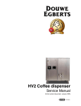
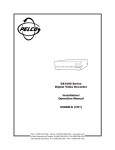
REPLACEMENT PARTS – Model 1400HT
FIREBRICK DIAGRAM
DOOR ASSEMBLY
FB-1
FB-1
FB-1
FB-1
FB11
FB-1
FB-1
Must Chip Approximately 1” x 1” Notches to Fit
HANDLE ASSEMBLY (P/N LB-102214)
FB-2
FB-2
FB-2
FB-2
FB-2
Torque Plate
FB-2
FB-2
FB-2
* Baffle Brick
5 ea. P/n 10545
FB5
Handle
Rod
FB-2
FB-2
Nut
Washers
Coil Handle
PRIMARY AIR DRAFT MODULE
PAGE 21
OPTIONAL ACCESSORIES – Model 1400HT
Note: Install and use accessories per instructions provided with the accessory kit.
Catalog # Description(Model)
Notes
14M66
3" Diameter Round
14M22
Outside Air Floor Duct
(OAFD-R)
Blower Kit (BK-100)
14M21
Stove Stat Kit (SSK)
70K99
Touch-up Spray Paint Kit,
Black (TSPK-B)
Blower Kit
A Blower Kit (includes rheostat for variable speed control)
is available for increased heat circulation.
Includes Dial-ATemp for Variable
Speed Control
Thermally Controls
Blower
12 oz Spray Can
Stove Rear Heat
Shield
160 CFM Blower
Assembly
Outside Air Floor Duct (OAFD-R)
2 Screws
10-24 x 1/2”
Outside air can be delivered for combustion air by utilizing this
floor penetration duct.
(Duct penetration measures 3” [76 mm] diameter round)
Variable Speed Control, Dial-A-Temp
Plug Dial-A-Temp
into Wall Outlet
Plug Power Cord
into Bottom of
Dial-A-Temp
Stove-Stat Kit
(Turns blower on when stove is hot and turns blower off when
stove is cool)
Stove-Stat
Magnetic Head
Blower
Assembly
Blower Power Cord Plug
Stove-Stat Power Cord Plug
Grounded 110 Volt Wall Receptacle
PAGE 22
SAFETY/LISTING LABEL
PAGE 23
EPA LABEL
PAGE 24
OWNERSHIP RECORDS
Dealer’s Name:
Dealer’s Address:
City:
State:
Zip Code:
Serial Number:
Date of Purchase:
Date Installed:
Notes:
SERVICE AND MAINTENANCE LOG
Service Service
Service
Date
Technician
Description
Page 25
1110 West Taft Avenue
Orange, CA 92865