1
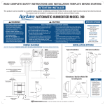
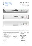
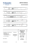
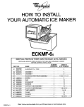
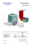
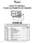
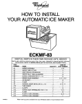
HUMIDIFIER
© 2003 Lennox Industries, Inc.
Dallas, Texas USA
504,882M
12/2003
HEALTHY CLIMATE® HUMIDIFIERS
INSTALLATION INSTRUCTIONS FOR LENNOX MODEL WB2-17 & WB2-17A
Specifications
ATTENTION INSTALLER:
This product must be installed by a qualified heating and air conditioning contractor.
This product must be installed in compliance with all local, state and federal codes.
!
BYPASS HUMIDIFIER
Model WB2-17 & WB2-17A
WARNING
Electrical Shock Hazard.
• Unit dimensions
131/8"W x 151/2"H x 91/8"D,
6" dia. round opening
Can cause injury or death.
Disconnect all electrical power supplies before
servicing.
!
WARNING
• Plenum Opening
93/4"W x 121/2"H
Risk of Property Damage, Injury or Death.
Installation, adjustments, alterations, service and maintenance must be
performed by your Lennox dealer.
!
• Water Feed Rate
6 gph
WARNING
• Electrical Data
24V-60Hz, 0.5 AMP
Risk of Scalding.
Water temperature over 125ºF can cause severe burns and scalding instantly.
Shut off the hot water supply before disconnecting or tapping into any hot
water supply line.
!
CAUTION
Risk Of Sharp Edges Hazard.
WB2-17A
Equipment sharp edges can cause injuries.
Avoid grasping equipment edges without protective gloves.
!
CAUTION
Risk of Property and Equipment Damage.
Water heating system can be damaged if water supply remains off.
For detailed humidifier control
installation and wiring instructions
see form Publication No. 504,879M
included with humidifier.
After humidifier installation is completed, turn hot water supply back on.
Water heating system must be de-energized if the main water supply remains
shut off.
Do not set humidity level above recommended or to recommended level if
condensation exists on inside windows of any unheated space, as condensation
damage may result. Excess humidity can cause moisture accumulation which
can allow the possibility for mold growth in your home.
Do not install unit in location where freezing temperatures may occur. The water
line could freeze and crack causing water damage to the home.
Do not install humidifier or bypass connection on furnace jacket.
Do not install humidifier or bypass connection on blanked off end of cooling coil
where airflow will be restricted.
Do not connect the transformer to multi-speed furnace blower motors or blower
motors other than 120 VAC.
Do not install humidifier where water pressures exceed 125 psi, since humidifier
damage may result. Follow codes in effect concerning pressure reduction.
Do not install power humidifier on supply plenum where static pressure exceeds
0.3” w.c.
TEMPLATE MUST BE LEVEL
— TOP —
READ REVERSE SIDE FIRST
READ REVERSE SIDE FIRST
READ COMPLETE WARNING AND CAUTION INSTRUCTIONS BEFORE STARTING
TEMPLATE MUST BE LEVEL
Lennox Healthy Climate® Humidifier – Models WB2-17 & WB2-17A
1.
Place unit on flat surface and pull front cover up
on right side. Lift evaporative media and scale control
insert out at the top
2. The unit is assembled for left side discharge. If
right discharge is necessary, remove the right and left
screws from the unit
interior side walls and
exchange the two sides.
Reassemble using existing
screws.
3. Using a level, position the template at least 1- / "
1
2
above the furnace housing or cooling coil (if
applicable), for clearance
of the drain line. Trace
around template edges.
Remove the template and
accurately cut the plenum
opening 93/4"Wx121/2H,
being careful to avoid
injury from sharp edges.
4. Place the unit into the plenum opening so that the
locking tabs on the bottom are closed down onto the
lower sheet metal edge.
While holding the unit in
place, install two screws
at the top of the unit
interior.
DISCONNECT THE ELECTRICAL POWER TO
FURNACE BEFORE PROCEEDING
LOCATION
a) Locate on inside wall of living area approximately 5'
above floor, or in the furnace return air plenum. Use
enclosed adapter plate for return air installation.
b) Do not locate control in the direct path of furnace
discharge air or drafts from open doors and
windows.
c) Do not install where operation might be affected by
lamps, sunlight, fireplace registers, radiators,
concealed air ducts and pipes, or next to activities
that generate moisture.
d) The basic rules for location of thermostats also
apply to humidistats.
GENERAL INSTRUCTIONS
a) DO NOT ATTEMPT TO REPAIR OR
RECALIBRATE CONTROL. Controls requiring
service should be returned to Lennox Industries.
b) Control must be installed to receive no more than
24 volts!
c) Make sure no bare wires are exposed or insulation
damaged. Insulation on wire should extend to head
of binding screws.
d) Make sure all splices are mechanically and
electrically secure.
e) To remove dirt or other foreign matter from nylon
ribbon and control interior, dust lightly with a fine,
soft brush.
7B.
HUMIDISTAT INSTALLATION INSTRUCTIONS
FOR WB2-17A.
For detailed humidifier control installation and wiring
instructions see form Publication 504879M, included
with humidifier.
8.
Shut off water supply. Open any faucet to
relieve water pressure.
5. Install a 6" collar in a convenient location on the
opposite plenum. Slip on a 90° elbow and measure the
length of 6" round duct required to make the
connection. The 6" duct will fit into the round collar on
the side of the unit. If the
system has central air
conditioning, add a duct
damper. Assemble
components using sheet
metal screws. Support
bypass ducts in excess
of 4' to prevent sagging.
6. Replace the evaporative assembly complete with
the evaporative media by fitting the drain tube into the
round receptacle at the
bottom of the unit. Push
the assembly in at the
top against the beveled
tabs. Replace the front
cover.
7A.
HUMIDISTAT INSTALLATION INSTRUCTIONS
FOR WB2-17
The humidistat is designed for low voltage service to
control humidification equipment. An increase in
relative humidity expands the nylon ribbon that opens
the control switch to stop operation on the humidifier. A
decrease in relative humidity reverses the process and
closes the control switch. See front for wiring diagram.
TO INSTALL ON COPPER OR PLASTIC PIPE
a) Place rubber gasket in
center of hole in top
saddle clamp. Place top
and bottom saddle
clamp around water
pipe. Using bolts, tighten
saddle clamps
evenly - clamps should be parallel - Do Not over-tighten.
b) Screw valve body into opening in top saddle clamp
and tighten.
c) Tighten gland nut onto valve body.
d) Install 1/4"water supply line from humidifier using
compression fittings.
e) You are now ready to pierce the pipe. Turn handle
until spindle is firmly seated into valve body. The
water pipe is now fully pierced. Turning spindle in
shuts valve off.
TO INSTALL ON STEEL OR BRASS PIPE
a) Drill 3/16" diameter hole into pipe where saddle
valve will be placed.
b) Place rubber gasket in center of hole in top saddle
clamp.
c) Place top saddle clamp assembly over hole so that
lance fits into hole.
d) Place top and bottom saddle clamp around water
pipe.
e) Screw valve body into opening in top saddle clamp
and tighten.
f) Tighten gland nut onto valve body.
g) Install 1/4" water supply line from humidifier using
compression fittings.
NOTE: For pipe over 1” O.D., use 1/4”-20, 1-3/4” long
bolts.
9. Tap into a water supply line with the saddle valve
furnished. The humidifier will function with cold, hot,
softened or unsoftened water. The use of service hot
water 140°F Max and constant blower operation will
provide maximum evaporative capacities. Note: The
saddle valve is designed to be fully opened or closed.
Do not use it to regulate water flow.
10. Connect tubing from the saddle valve to the inlet
side of the solenoid valve using 1/4” O.D. copper tubing
(not furnished). DOUBLE WRENCH TO PREVENT
LEAKING AND VALVE BREAKAGE!
11.
Connect 1/2” I.D. plastic hose (not furnished)
from unit to floor drain. Be
sure drain hose has
continuous slope. Use
caution if hose clamp is
used to not over tighten
and crack drain spud.
NOTE: Do not sweat or
directly attach metal
drain line to fitting. Do not use solvent type
adhesive when connecting plastic drain hose,
since damage to fitting could result.
12. Turn water on.
13. Open saddle valve completely and turn on
furnace.
WB2-17 – Adjust
humidifier setting so that
humidifier will turn on.
Allow humidifier to run
until water is observed
coming out of drain line.
Check to see if unit is
watertight. Check operation to make sure that all
electrical components function properly. Set humidistat
to recommended level. (See operating instructions in
owners manual)
WB2-17A – Check to see if unit is watertight. Check
operation to make sure that all electrical components
function properly. Use humidification "System
Checkout" section of Automatic Humidifier Control
Installation Instructions, Publication No. 504,879M.
HEALTHY CLIMATE®
H U M I D I F I E R
10006151
B2203306A