1
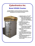
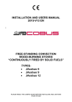
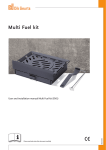
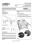
HEARTH PRODUCTS
KITS AND ACCESSORIES
P/N 506033-56
Rev. NC, 08/2011
GRANDVIEW™ BLOWER KIT
INSTALLATION INSTRUCTIONS FOR INSTALLING the blower
on a GRANDVIEW™ 230 WOODSTOVE
Installation Instructions
KIT CONTENTS
Please ensure that all these parts are included
Step 1. Remove round knockout plate on back of stove by removing the
screw on the top of the knockout with a 5/32” allen wrench. You
can then push on the top and bottom of the plate to loosen for
removal.
Step 2. Install the four supplied flat Tinnerman nuts into the four rectangular slots on the back of the stove. Use of a flat head screw
driver will be necessary.
1 ea. Blower w/snap switch assembly
6 ea. 10-24 Screws
4 ea. Tinnerman nuts
Grandview™ Blower Kit
Cat. No.
Model
H8350
BLWR-GV-700-SS
Description
Blower
Snap Switch
TOOLS NEEDED
Flat Head Screwdriver
5/32” Allen Wrench
1/8” Allen Wrench
GENERAL INFORMATION
If you encounter any problems, need clarification of these instructions or
are not qualified to properly install this kit, contact you local distributor
or dealer.
Read this instruction sheet in its entirety before beginning the installation.
ALL WARNINGS, PRECAUTIONS AND INSTRUCTIONS IN THE INSTALLATION AND OPERATION MANUAL PROVIDED WITH THE APPLIANCE
APPLY TO THESE INSTRUCTIONS.
Check the contents of the kits upon receipt and check for any damaged
or missing parts. If there is hidden damage, notify your freight company
or Lennox Hearth Products dealer immediately.
CAUTION: Wear gloves during installation in case of sharp
edges on the stove.
Tinnerman Nut
Figure 1
NOTE: DIAGRAMS AND ILLUSTRATIONS ARE NOT TO SCALE.
1
Step 3. Install the four supplied allen screws into tinnerman nuts, leaving
loose. A 1/8” allen wrench will be necessary.
Step 4. Place blower keyhole mounting slots onto the four installed screws
and slide assembly downward, ensuring all mounting screws are
holding blower in place. Tighten all four screws snugly. NOTE*
POWER CORD WILL BE ON THE BOTTOM.
Step 5. Install temperature activated switch bracket into rectangle cutout,
in the upper right corner on rear of stove, with wires facing outward from the actual firebox. Secure with the larger two supplied
allen head screws. A 5/32” allen wrench will be necessary. NOTE*
ENSURE TEMPERATURE ACTIVATED SWITCH IS MAKING FIRM,
FLAT CONTACT WITH SIDE OF FIREBOX.
Step 6. Plug power cord into 120V wall outlet.
Figure 2 - Installed Blower w/ Snap Switch
BLOWER OPERATION
The blower can be operated in either manual or automatic mode. When
operated automatically, the blower will turn on when the stove is hot, and
turn off when the stove is cool.
MANUAL OPERATION
Flip blower mode switch to the manual position (up) and adjust blower
speed dial to desired setting. to turn blower off, rotate blower speed dial
counter clockwise until it clicks “OFF”.
Auto operation
Flip blower mode switch to auto position and turn blower speed dial
clockwise until it clicks out of the “off” position. When the stove warms
up (approx. 15-20 Mins), the blower will automatically turn on (adjust
blower speed dial to desired speed setting. When the stove cools down,
the blower will automatically turn off.
Figure 3 - Blower Controls
NOTE: DIAGRAMS AND ILLUSTRATIONS ARE NOT TO SCALE.
Lennox Hearth Products reserves the right to make changes at any time, without notice, in
design, materials, specifications, prices and also to discontinue colors, styles and products.
Consult your local distributor for fireplace code information.
2
Printed in U.S.A. © 2011 Lennox Hearth Products
P/N 506033-56 Rev. NC 08/2011
1508 Elm Hill Pike, Suite 108 • Nashville, TN 37210