1
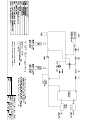
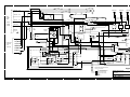
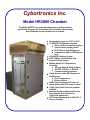
Cybortronics Inc.
Model HR3690 Chamber
The Model HR3690 is a single bay temperature cycling chamber
specifically designed for the commercial electronics environment.
Specifications for the chamber are as follows:
• Temperature range of –10°C to 80°C
• 72,000 BTU Refrigeration System
• Water cooled condenser requires
•
•
•
•
•
•
•
•
external water cooling tower.
• R-507 Ozone Safe Refrigerant
• Compressor Inhibit if Refrigerant
lost
40,000 BTU Heating System
1500 CFM Air Recirculation with
Vertical Airflow design
Watlow Model 981 Temperature
Controller
• 20 step Ramp & Soak profiling
• RS-232 , RS-422, or EIA 485
Communications Interface
Safety Alarms with LED Display and
Audible alert
• Over-Temperature
• Blower Failure
Front Panel Display and Control of
Alarm Status and UUT Power Control
Triple Pane Glass Doors for product
visibility
Brushed Stainless Steel and Granite
Grey Powder-Coat Exterior for
High-Tech appearance
AC Power requirements of 208 VAC, 3
Phase, 60 Amps
Section I
HR3690 Chamber Functional Description
Following is a functional description of the various elements of the HR3690 Chamber. These elements consist of the Front Panel, the Air Recirculation System, the
Heating System, the Cooling System, and the Alarm System. Please see Figure 1.1
for a complete schematic of the electrical components of the HR3690 Chamber. All
serviceable component parts with the exception of the blower and the refrigeration
components are located under the ‘hood’ of the chamber. This hood is hinged at the
top and has two philips screws in the lower left and right corners to allow access to
the Power Control Panel, the CYB20480 Relay Module, and the Watlow Model LV
Over-temperature Limit Control.
Front Panel The Front Panel contains the Watlow Model 981 Temperature Controller, the UUT
Power Control, and the Alarm Control . Please see Figure 1.3 for the layout of this
panel. The Watlow Temperature Controller is the ‘brains’ of the chamber, controlling
all heating and cooling functions. Output 1 (L1) of the controller is connected to the
heating circuit. Output 2 (L2) is connected to the cooling circuit. The fourth output
(L4) is the RS-232 communications interface. The L4 LED will flash whenever serial
data is being sent from the controller. Please see Figure 1.4 for a quick guide to the
Watlow operation. All further details of the Watlow can be found in the Watlow
‘Series 982 User’s Manual’. Data communications interfacing and commands can
be found in the ‘Data Communications with the Watlow Series 988 Family of
Controllers User’s Guide’.
The UUT Power Control consists of a switch to control the On/Off state of the AC to
the UUT outlets in the optional CYB20440 AC Distribution Panel. See Section III for
a description of this unit if this option is installed. An LED shows the status of this
switch.
The Alarm Control consists of LED’s showing the status of the Over-temp, AC
Phase, and Blower alarms. If the associated LED is on, then an alarm condition exists. The Audible switch allows resetting the Over-temp alarm if this alarm condition
exists.
Air Recirculation System An 1500 CFM blower is powered continuously from 208 VAC through fuses F14 and
F15. This blower pulls air vertically up through the product, the refrigeration system’s
evaporator coil, across the heating coils, and then directs the airflow down the back
wall of the chamber.
Heating System The heating circuit is comprised of three 4000 watt nichrome heating elements
mounted just above the evaporator coil in the top of the chamber. For safety reasons,
three Solid State Relays (SSR2, SSR3, SSR4) are used to control these heating
elements. Each heater is removable and is fused at 40 amps by fuses FA, FB, and
FC . The negative control line to all three SSR’s is the L1 output of the Watlow 981
Temperature Controller. If Output 1 (L1) is on, this terminal is grounded and will turn
on the SSR’s. The positive control line to the three SSR’s is a switched +12 VDC line.
This line will be opened by the K1 or K2 relays on the CYB20480 module if an
Over-temp or Blower alarm condition exists. All three legs of the 208 VAC input power
will then be removed upon an alarm condition.
Cooling System The cooling circuit consists of an 6 HP Copeland Compressor System with an associated control circuit. The system uses ozone safe R-507 refrigerant. Output 2 (L2) of the
Watlow 981 Temperature Controller, when active, will turn on the refrigeration solenoid
by grounding the negative side of SSR1. At the same time, relay SP2 on the
CYB20480 module is energized which closes the contact to the Off Delay Timer. The
timer then applies 115 VAC thru the pressure switches to contactor K2 to turn on the
208 VAC three phase to the compressor. Time delay fuses (F11, F12, F13) of 25 amp
capacity are used for the compressor due to the motor start-up current draw. If the
compressor has lost refrigerant, the pressure switches will open, disabling contactor
K2. The timer will keep the compressor running for a minimum of 3 minutes even if
Output 2 has turned off. This extends the life of the compressor by assuring proper
separation of the Freon and oil in the compressor. The flow of Freon is controlled by
the solenoid valve controlled by SSR1. When the Freon flow is turned off but the
compressor is still running, a ‘hot gas bypass’ valve is opened to allow the Freon to
re-circulate.
Dry Air Purge System—(Optional)
A Dry Air Purge System is installed on the rear of the chamber to provide a dry environment in the chamber. This system requires a connection to a dry compressed air
supply of 60 PSIG.
Alarm System The AC Phase Alarm , when lit, will disconnect the ground line from the +12 VDC
power supply from all circuitry in the chamber . This will inhibit all chamber operation. This alarm indicates that the 208 VAC connected to the chamber is not connected in the proper phase. The compressor used in the refrigeration circuit cannot
be operated unless proper phasing of the AC supply is present. Usually just switching two of the phases at the AC source to the chamber will correct this problem. The
AC Phase Monitor on the Control Panel will have its LED lit when it detects proper
phasing.
The Over-temp Alarm consists of a Watlow Model LV Limit Control that when activated, turns on relay K1 on the CYB20480 module. This in turn will close contacts to
turn on the front panel LED indicating an alarm condition and turn on the Sonalert
audible device. Another set of contacts will open the +12 VDC line controlling the
SSR’s used for the heating coils. This switched +12 VDC line is also used in the interface cable to the optional AC Distribution Panel. This will turn off the SSR’s in this
panel and remove all AC from the UUT’s, removing all heat load from the inside of
the chamber and protecting the UUT’s from damage. The Over-temp Alarm is a
latching alarm and will stay active until the problem is resolved and the alarm is
manually reset. The reset switch is a momentary rocker switch located below the
Alarm Display on the front panel. The chamber is shipped with the Over-temp Alarm
set to 80°C. Access to this control is obtained by raising the ‘hood’ of the chamber.
The Blower Alarm is an air-flow switch which when activated due to a blower failure
or slow spin condition, will turn on relay K2 on the CYB20480 module. A set of contacts will then turn on the front panel LED indicating the alarm condition along with
the Sonalert sounding. A second set of contacts performs the same functions as the
Over-temp Alarm, turning off the heaters and the AC to the UUT’s. This alarm is
self-resetting.
1
2
3
4
5
6
F13 TRM25
PHASE 3
7
COMPRESSOR
F12 TRM25
Blue
CS1
8
PHASE 2
Red
MAIN
POWER
INPUT
3
L1
4
L2
5
L3
3 Phase
Line Monitor
4KW Heater
4KW Heater
F11 TRM25
A
8
CS2
Hi Side Pres.
2
4KW Heater
Low Side Pres.
A
K2
Compressor
Solenoid
1
Bypass
Solenoid
LED On When Phase OK
A3T40
A3T40
AC
SSR1
SSR-40A
-
AC AC com no nc
OVERTEMP
TRM8
CONTROL
F5
80
+
3
F15
TRM8
4
F14
GROUND
2
1
2
AC
AC
AC
AC
AC
SSR4
SSR-75A
SSR3
SSR-75A
SSR3
SSR-75A
-
+
-
+
-
+
3
AC
AC
4
2
60 AMPS
1
NEUTRAL
3
3 PHASE
A3T40
1
FA
4
FB
208 VAC
2
FC
3
F4 AGC5
1
Black
4
PHASE 1
RELAY
K3
AGC5
B
B
SET
P1
BLWR
15A
BLOWER
+
Load
`T'
LS1
Control Line
Plug
sw
Power Pack
-
MAIN
sw
12 VDC
TC+ TC- SW SW
F1
1
2
Off Delay Timer
SWITCH
Dehumidifier
Line
F10 AGC10
RELAY
K1
Dehumidifier AC
+
F2
15A
Distribution
Panel
F7
15A
CYB20477A
F8
To Optional AC
SONALERT
F9
11
2
3
15A
13
14
15A
16
17
J2
14
13
12
11
10
9
8
7
6
5
4
3
2
1
J1
23
RJ-45
TEMP
CONTROL
5
6
7
9
C
RS-232 to
CPU
22
WATLOW
TxD
RxD
GND
10
1
-
D2
C
`T' Type
+
2
D1
JP1
1
2
3
4
5
6
7
8
Thermocouple
3
4
6
6
4
4
6
4
8
8
8
11
11
13
13
11
13
9
9
16
16
1
K3
K1
PWR
ON
S1
5
6
PWR ON/OFF
7
AUDIBLE RESET (Mom.)
BLWR
ALM
PHZ
ALM
OT
ALM
SYS
PWR
9
16
1
K2
S2
1
FRONT PANEL
LED'S AND SWITCHES
8
CYB20480 MODULE Rev. B
On/Off Control for External Device
D
Figure 1.1
Cable on rear of Chamber
D
J3
1
2
3
4
5
6
Switched Ground
By Power On/Off Switch
Cybortronics Inc.
13845-C Alton Pkwy.
Irvine, CA 92618
1-800-289-8203
Switched +12 VDC
By Alarm Condition
Title
HR-3690 MAIN CONTROL SCHEMATIC
6 PIN MOLEX
Size
Document Number
Custom
CYB3690-SCH
Date:
1
2
3
4
5
6
7
Tuesday, March 18, 2008
Rev
A
1
Sheet
8
of
1