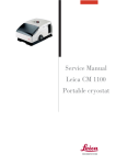
1
Leica AG, CH-9435 Heerbrugg (Switzerland)
Telephone +11 (071) 70 31 31, Fax +41 (071) 72 69 52
Leica is a registered trade mark of Leica technologij B. V. Rijswijk, the Netherlands
Legal matters
Revisions/Service News
Service Manual
Introduction / User manual
Fault finding with testset
WILD M695
Control unit MEL61/62, MEL64/65
5
Swingarm MSV 136/137
6
Microscope M695
7
8
Wiring diagram
9
Replacing modules
Replacing boards
Inspection procedure
12
13
14
15
16
Training
17
Testset
Spare parts catalogue
19
Special tools
20
Service Manual M695
Doc Code 636 718
Legal questions/ Safty-Rechtsfragen / Sicherheit
09/93 3691-DMF
lnhaltsvetzeichnis / Table of contents
Kapitel
Seite
Rechtsfragen / Legal questions ...................................................................................... 1
Sicherheit / Safety / Securite / Seguridad ....................................................................... 3
Service Manual M695
Doc Code 636 718
Legal questions / Safty-Rechtsfragen / Sicherheit
09/93 3691-DMF
Copyright
Ohne vorherige schriftliche Erlaubnis der Firma Leica AG, Heerbrugg (Schweiz), darf dieses Dokument
weder insgesamt noch auszugsweise mit mechanischen, fotografischen, elektronischen oder irgendwelchen
anderen Mitteln (einschließlich ihrer Umwandlung oder Übertragung in maschinenlesbarer Form) kopiert,
in einem Informationsspeicher abgelegt, außerhalb des dafür vorgesehenen Zwecks oder in irgend einer
Form an von Leica AG, Heerbrugg nicht ausdrücklich befugte Dritte zuganglich gemacht oder abgegeben
werden.
Haftung
Dieses Dokument richtet sich ausschließlich an qualifizierte Servicetechniker und Servicetechnikerinnen,
welche über die notwendigen Fachkenntnisse verfugen.
Qualifizierte Servicetechniker und Servicetechnikerinnen sind solche, die den entsprechenden Servicekurs
bei Leica AG, Heerbrugg erfolgreich besucht haben und bei Unternehmen der Leica Gruppe oder bei von
Leica AG, Heerbrugg autorisierten Vertretungen oder Servicewerkstätten tätig sind.
Wird dieses Dokument von nicht qualifizierten Servicetechniker und Servicetechnikerinnen verwendet, so
lehnt Leica AG, Heerbrugg jegliche Haftung ab für direkte und indirekte Schaden, die durch nicht
fachgemäße Anwendung und/oder Interpretation dieses Dokumentes entstehen.
Copyright
Without prior permission in writing by Leica AG, Heerbrugg (Switzerland), this document shall not be
reproduced as a whole or in part, by mechanical, photographic, electronic, or other means (including into or
transmission in machine-readable form); stored in any retrieval system; used for any purpose other than
that/those for which it is intended; nor made accessible or communicated in any form to any third party not
expressly authorized by Leica AG, Heerbrugg to have access thereto.
Liability
This document is strictly for the use of qualified service engineers with the requisite technical skills.
Only persons who have successfully completed the appropriate service training provided by Leica AG,
Heerbrugg and are in the employ of a Company in the Leica Group or of an agency, distributor, or Service
Workshop duly authorized by Leica AG, Heerbrugg have the status of qualified Service engineer.
Leica AG, Heerbrugg accepts no liability whatever for direct or indirect damage that may occur due to the
unauthorized or improper use or interpretation of this document by any person who is not a qualified
service engineer in accordance with the above definition.
Service Manual M695
Doc Code 636 718
Legal questions / Safty-Rechtsfragen / Sicherheit
09/93 3691-DMF
Für die Servicetechniker und Servicetechnikerinnen gelten folgende Pflichten:
• Sie verstehen und befolgen die Sicherheitsinformationen und die Instruktionen auf dem Produkt sowie in
der Gebrauchsanleitung.
• Sie kennen die ortsüblichen gesetzlichen, betrieblichen und ausserbetrieblichen
Unfallverhütungsvorschriften im Wissen, dass sich diese auf dem aktuellsten Stand befinden.
• Sie benachrichtigen Leica schriftlich, sobald an der Ausrüstung Sicherheitsmangel auftreten.
Service technicians have the following obligations:
• To understand and follow the safety information and instructions on the product and in the user manual.
• To be familiar with local regulations relating to industrial and non-industrial accident prevention in the
knowledge that these regulations are up to date.
• To inform Leica immediately in writing if the equipment becomes unsafe.
October 94
Leica AG, Heerbrugg
REVISION
Documentation
: WILD M695 Service manual
(Technical description and fault finding)
Status
: Edition 09(93
/
Revision, previous: ------new: 10/94
Reason for revision : M680 control unit (MEL61/62) is compatible with M695
Steps to be taken
File
:
Section
Remove page(s)
Number of
sheets
Introduce page(s)
Number of
sheets
----2
9
19
title sheet
index register
--9-1 to 9-8
19-1
1
1
-4
1
title sheet
index register
2-1/2
9-1 to 9-8
19-1
1
1
1
4
1
: Insert this sheet (Revision) in section 2.
Leica AG
Service Documentation
and Training LSG/SOM/SM
SOM and SM Service News
Surgical Operating Microscopes
No. 10/95
Leica AG
CH-9435 Heerbrugg
(Switzerland)
To Service staff
Date/from
June 28, 1995 / 3077-HWE
File Workshop binder “Service News” / Service manual M695
Re. M695 surgical microscope in conjunction with
multifocus objective 445 944
Multifocus objective on M695:
Readjustment of the illumination
Restriction of illuminated
area
When the multifocus objective is used with the M695, the illuminated
area available to the surgeon may be shadowed or vignetted even when
the the lamp is correctly adjusted.
lnspect the illumination
When you use the multifocus objective for the first time, inspect the
illumination:
l
Engage the shortest working distance (the shortest focal length).
l
Engage the lowest zoom position (7).
l
l
Readjusting the lamp
Inspect the illuminated fields produced by both of the lamps in the
lamp changer.
If the illuminated area is noticeably restricted, readjust the lamps.
The illumination of the field of view is influenced by the distance
between the lamp and the condenser lens. This distance can be changed
by means of the eccentric stop cam on the lamp changer. To obtain
uniform illumination, reduce the distance between the lamp and the
condenser lens.
Adjust the eccentric stop cam for both lamps in the lamp changer:
1. Remove the multifocus objective and push the filter slide of the
M695 optics carrier towards the objective. Beneath the filter slide
you will find the adjusting screw for the eccentric stop cam.
2. Using a screwdriver, displace the eccentric stop cam by about oneeighth of a turn so that the lamp can be moved in the direction of the
objective.
CAUTION: The lamp may be hot.
3. Switch to the second lamp, and carry out point 2 for this lamp.
4. Refit the multifocus objective and inspect the illumination as
described above.
5. If necessary, repeat the adjustment procedure (points 1 - 3).
Leica AG
Service SOM/SM
W. Hammerle
SOM and SM Service News
No.
To
Service staff
Date/from May
File
Refer to
Leica AG
CH-9435 Heerbrugg
(Switzerland)
09 / 95
29, 1995 / BKL-3402
Workshop binder “Service News” / Service Manual M695
Necessary replacement of SOM product “Light intensifier”
No. 445 796
Faulty product has to be exchanged
Delivery of faulty
SOM product "Light
intensifier” 445 796
The concerned product has been delivered to the following countries as
single part or included in the delivery of optics carriers:
Netherlands, Japan UK, Italy, Australia, USA, Sweden, Canada,
Switzerland, Korea, South Africa, Kuwait, Belgium, Spain Columbia,
Saudi Arabia, France, Singapore, Finland, Portugal, Germany, Denmark,
Algeria, Sudan, Luxembourg, Dominikanische Republic, Hong Kong,
Turkey, Brazil, Tunisia, Israel, Austria, Jordanian India.
All other countries are not concerned.
Problem:
Since market introduction in March 1994 up to March 1995 the concerned
product has been delivered faulty (The cement does not withstand the high
temperatures at the bulb). It has been delivered as a single part as well as
included in the following optics carriers:
M690 optics carrier Mitaka
445 543
M695 optics carrier
445 560
M695 optics carrier Mitaka OH 445 841
Since March 1995 an improved version with the same No. has been
delivering. The two versions can be distinguished easily according to the
drawing on page two.
Action:
The concerned customers are already informed by your Management.
The faulty products have to be replaced, please contact your Marketing
responsible for SOM products.
All concerned countries will be supplied automatically without any
order with sufficient replacement units, free of charge.
The exchange procedure is very simple and can be achieved by the
customer himself as well. If you will not carry out the exchange yourself,
supply the customer with sufficient exchange units and Information.
SERNEWSE.DOC
1/2
The action of replacement has to be achieved ASAP and should be
finished by end of September ‘95 at the latest.
Please send a feedback after fully finish of the action of exchange with a
list of all concerned customers to the
SOM HOTLINE: Fax: ++41 - 71 - 72 26 77
This is necessary for reasons of product liability.
Your expenses on this action will be refunded by us via the ‘Repair Report
to Factory” (Please fill out the report completely, one report for the
complete action!).
Fig.1:
The improved (second) version has
approx. 5 mm cement free area in the center,
good improved version
where at the old version the whole is completely filled with
cement.
Leica AG
Service SOM/SM
Klaus Bieniek
SERNEWSE.DOC
2/2
Service manual M695
Doc Code 636 718
Modification
10/94 3077-HWE
Changes and modifications
M680 control unit (MEL61/62) is compatible with
M695 surgical microscope
. . . from control unit
serial number 011193001
onwards
the MEL61/62 can also be used for the M695, provided that earlier lamp
control PCBs are subjected to a slight modification. This modification was
introduced from March 1993 onwards (Index C on board) (355 980 C).
The functions ZOOM SPEED B, XY-SPEED and POSITION 1/2 are not
required for the M695. The positions occupied on the control panel by
these switches or potentiometers will be covered over. The covers, and
instructions for fitting them, accompany the control unit.
From March 1995 onwards, only the MEL61/62 control unit will be used
for the M680 and M695. The previously-used MEL64/65 control unit will
no longer be manufactured.
Modification of the
lamp-conbol PCB
is required if both of the following conditions are met:
1. The MEL64/65 control unit is replaced by an MEL61/62
2. The M695 was despatched before March 1993. The lamp control PCB
therefore bears an earlier index than C.
Under these conditions the hand-/footswitches will not react at the control
input A or B respectively, depending on the position of the switch
"Position 1/2".
Modification: On the soldered side, bridge pins 10 and 12 of P20 with a
100 Ω resistor (1/8W). The resistor shall not come into contact with the
housing cover.
2-1
Modifications
10/94 3077-HWE
2-2
Service manuel WILD M695
Doc Code 636 718
Introduction
03/93 3077-HWE
Service Manual M680
Doc code 556 848
Preconditions
for using this service manual
Intended users
What is expected of
the person using the
Testset?
Technical personnel provided by customer or by LEICA agencies, equipped
with the testset 566 152 (see Section 18).
Stage 1: Allocation of a fault to one of the main groups:
-
Footswitch
Control unit
Swingarm
Microscope (optics carrier)
•
You have read the user manual and can operate the surgical microscope
Directions are given in Sections 3 and 4.
Stage 2: Locating and eliminating errors at module level
•
You have been trained in the basics of electronics and mechanical
engineering
•
You have been instructed by a technician from your agency or from
LEICA AG, HEERBRUGG.
Sections 3,4 and 10
Stage 3: Locating and eliminating errors at board level
•
You have been trained in the basics of electronics and mechanical
engineering
•
You have taken part in an M690/M695- or M680 course.
Sections 3 to 9, and Section 11
3-1
Service Manual M680
Doc code 656 948
Introduction
03/93 3077-HWE
To the contents of service manual
Legal aspects
This book may only be given to, and used by, certain persons. These are
detailed in Section 1.
Changes/
Service News
Place Service News on top of the M695 in Section 2.
Introduction/
User manual
CONGRATULATIONS - You are one of those methodical people who also
read the important Section 3 of this manual.
locating faults with
the test set (Test box)
If a fault develops, we will guide you to it with the assistance of Section 4
and the test box.
The test set helps you to assign the fault to the:
• Footswitch
• Control unit
• Swingarm
• Microscope
The search is then continued at board level with the assistance of block
diagrams and the wiring diagram.
Control unit MEL64165
Description of function
3-2
The function description in Section 5, in conjunction with the wiring diagram,
will lead you to the defective board or cable connection. The swingarm is the
interface.
Service Manual M680
Doc code 556 948
Introduction
03/93 3077-HWE
Swingarm
Description of function
The function description in Section 6, in conjunction with the wiring diagram,
will lead you to the defective board or cable connection. The swingarm is the
interface.
M680 microscope
Description of function
The function description in Section 7, in conjunction with the wiring diagram,
will lead you to the defective board or cable connection. The swingarm is the
interface.
Wiring diagram
Section 9 contains the wiring diagram, and a description of the positions of
the boards and the plug connections.
Exchanging modules
Section 10 includes instructions for exchanging those modules which are
available as spare parts.
Exchanging boards
Section 11 includes instructions for exchanging those boards which are
available as spare parts.
Testing procedure
After modules or boards have been replaced, the instrument must meet
specifications. Values and tolerances are laid down in the testing procedure
in Section 12.
Test set
The test box and service cable, and their circuits, are described in Section 18.
Spare parts
The spare parts, the exchange of which is described in Sections 8 and 9, are
listed in Section 19.
Introduction
03/93 3077-HWE
Special tools
Service Manual M680
Doc code 556 948
Section 20 includes a list of the service equipment which will enable you to
carry out the operations described above.
No special tools are required. The components making up the test box include
a service handswitch and a service cable which serves to bridge the swingann.
3-4
User Manual
08/98
Service Manual M695 (CD-ROM)
Doc code 636 718
The M695 User Manual is provided as a separate document.
To view it, click on this text.
Service manual M695
Doc code 636 718
M695 fault finding
09/93 3077-HWE
Table of content
M695 fault finding
Chapter
Page
Preparation
4-1
Power supply of control unit
4-3
Functions of hand- or footswitch
4-4
Supply of microscope
4-5
Lamp control
4-7
Zoom control
4-8
Focus control
4-9
Service manual M695
Doc code 636 718
M695 Fault finding
09/93 3077-HWE
M695 Fault finding
Preparation
1. Connecting the testbox
l
Disconnect plug P36 from swingarm
l
Hook in the testbox to the swingarm and plug in P36 at the testbox.
l
l
Connect the testbox cable (green sleeve) with J36 at the swingann. With
that the control unit is connected with the microscope through the testbox.
Set switch “MICROSCOPE SELECT” on the testbox to position A.
4-1
Service manual M695
Doc code 636 718
M695 Fault finding
09/93 3077-HWE
2. Settings on the control unit
•
4-2
Adjust Lamp to minimal brightness
M695 Fault finding
09/93 3077-HWE
Service manual M695
Doc code 636 718
Power supply of control unit
Action
Reaction
Possible reason
Check
SWITCHING ON
Lamp of main switch
does not light
Line voltage
Fuses F1 and F2 in
line plug P1
Main switch S1
Line cable
5V-LED on FunctionDisplay does not light
Focus does not move
to center position
24V-main supply
Transformer
Rectifier circuit
Wiring
10V-supply
Panel board
5V-supply
Receiver board
Control unit,
Swingaxm o r
microscope
Focus control
page 4-9
4-3
Service manual M695
Doc code 638 718
M695 Fault finding
09/93 3077-HWE
Functions of hand- or footswitch
Condition:
Malfunction of hand- or footswitch of only one of the two CONTROL-inputs,
A or B
is disturbed.
•
Replace disturbed hand- or footswitch ective side A or B by either:
a) Service-handswitch or
b) Hand-/footswitch at the other CONTROL-input
Action
Reaction
Possible reason
Corresponding LED at Function
Display does not light
Receiver Board
Release functions:
Connect again original switch
and
release functions
Corresponding LED at Function
Display does not light
Hand- or footswitch
M695 Fault finding
09/93 3077-HWE
Service manual M695
Doc code 636 718
Reaction
Possible fault
Microscope reacts but incorrect
Check supplylines of 24V and
check PGND page 4-6
Microscope without
any function
Wiring of
microscope
Switch off, bridge swingarm with servicecable and 26V +-5%
switch on again
microscope reacts
Swingarm cable
Switch off,
Separate microscope from 26V +-5%
testbox and switch on
Voltage ok
evtl. short circuit
in the microscope
Voltage not ok
Control unit
Reading
Voltage
Action
24V
1.Lamp to min.brightness 26V +-5%
2.Lamp to max.brightness 20V +-5%
3.Lamp back to min.
brightness
MICRO
4-5
M695 Fault finding
09/93 3077-HWE
Service manual M695
Doc code 636 718
Check lines of Powerground PGND
(Voltage drop on PGND relating to logic ground)
Signal
Action
FOCUS UP
Adjust lamp to maximal max. -0.8W
If voltage is ok - depending on the incorrect
brightness
with standard- function, check signals of:
swingarm
Lamp control - page 4-7
cable
Zoom control - page 4-8
Focus control - page 4-9
Reading
Bridge swingarm with max. -0.8V
service cable and adjust
lamp to max. brightness
Reaction
Voltage ok
Swingarm cable
(One of the two
PGND-lines is
broken)
Voltage not ok
typ. >-1v
One of the two
PGND-lines in
the microscope
or control unit is
broken.
Important: Adjust lamp again to minimal brightness!
4-6
Possible fault
M695 Fault finding
09/93 3077-HWE
Service manual M695
Doc code 636 718
Lamp control
Possible fault
Signal
Action
Reading
Reaction
LAMP REF
Adjust lamp to min./max
brightness
0.3V / 5V
+-5%
Voltage ok
Separate microscope
from the testbox,
adjust lamp to min./max
brightness
0.3V / 5V
+-5%
Voltage ok
Microscope
Bridge swingarm with
service cable,
adjust lamp to min./max
brightness
0.3V / 5V
+-5%
Voltage ok
Swingarm cable
Voltage not ok
Control unit
Microscope
(Lamp Control,
Wiring)
Important: Adjust Iamp again to minimal brightness!
4-7
Service manual M695
Doc code 636 718
M695 Fault finding
09/93 3077-HWE
Zoom control
Action
ZOOM SPEED Set min. zoom speed
Set max. zoom speed
Heading
Reaction
Possible fault
Voltages ok, but
reacts incorrect
Microscope
(Logic board.
Zoom servo,
wiring)
1.84 ... 2.34V
5V +-5%
ZOOM UP
/footswitch
>4.75V
non-actuated
<0.2V
/footswitch
>4.75v
non-actuated
<0.2v
Separate microscope
from the testbox and
check signals
see above
Voltages ok
Microscope
(short circuit on
Zoom servo or
wiring)
Bridge swingarm with
servicecable and verify
signals
see above
Voltages ok
Swingarm cable
Voltages not ok
Control unit
ZOOM DN
4-8
Service manual M695
Doc code 636 718
M695 Fault finding
09/93 3077-HWE
Focus control
Select microscope side A or B:
•
Select A or B, depending on which side the zoom works incorrect
•
Select A if the fault appeares on both sides, A and B.
Action
FOCUS SPEED set min. focus speed
set max. focus speed
Reading
Reaction
Possible fault
Voltage ok, but
reacts incorrect
Microscope
(Focus servo,
wiring)
1.25 . . . 1.27V
5v +-5%
FOCUS UP
/footswitch
>4.75V
non-actuated
<0.2V
/footswitch
>4.75V
non-actuated
<0.2V
Separate microscope
from the testbox and
check signals
see above
Voltages ok
Microscope
(short circuit on
Focus servo or
wiring)
Bridge swingarm with
servicecable and verify see above
signals
Voltages ok
Swingarmcable
Voltages not ok
Control unit
FOCUS DN
M695 Fault finding
09/93 3077-HWE
4-10
Service manual M695
Doc code 636 718
Description control unit MEL64/65
09/93 3077-HWE
Service manual M695
Doc code 636 718
Description of functions
MEL64/65 control unit
Chapter
Page
Introduction
5-1
Power supply
5-3
Lamp control
5-9
Zoom control
5-11
Focus control
5-15
Description of control unit MEL64/65
09/93 3077-HWE
Service manual M695
Doc code 636 718
Description of functions
MEL64/65 control unit
The description is subdivIded for the main groups:
•
Control unit MEL64/65 - Section 5
•
Swingarm MSV136/137 - Section 6
•
M695 microscope - Section 7
The control circuits for zoom, focusing and XY-gear
are located partly in the control unit and partly in the microscope itself. Their
functions are described in the following sections 5 and 7.
The swingarm cable
is the electrical link between the control unit and the microscope, and is
therefore the ideal place to start looking for faults at the level of the main
groups.
The test box is introduced between the swingarm and the microscope. It can
be used to study the supply voltages, control signals and control levels, all of
which are transmitted through the swingarm cable. Section 6 includes a list
of these signals.
5-1
Description of control unit MEL64/65
09/93 3077-HWE
Notes
Service manual M695
Doc code 636 718
Description of control unit MEL64/65
09/93 3077-HWE
Service manual M695
Doc code 636 718
Power supply MEL64/65
Control elements /displays
Pages
24V supply
for microscope and XY-gear
Red LED on panel board indicates
defective fuse
5-6
10V supply
for potentiometer and receiver board
Green LED on panel board shows 10V
OK
5-6
5V supply
for logics of receiver board and footswitch or handswitch
LED “5V” OK on function display
5-7
PGND: Microscope ground
Yellow LED on panel board indicates
switch-off caused by excess current
5-7
SENS
Logics (ground) microscope
5-7
Ground
GND_XY: XY ground
Description of control unit MEL64/65
09/93 3077-HWE
Service manual M695
Doc code 636 718
Service manual M695
Doc code 639 718
Description of control unit MEL64/65
09/93 3077-HWE
Service manual M695
Doc code 636 718
Description of control unit MEL64/65
09/93 3077-HWE
Control-LEDs
On the panel board:
10V OK: green LED shines
>5A on 24V (PGND): yellow LED shines
Fuse interrupted: red LED shines
and on the function display:
5V OK: green LED shines
24V supply
The 24V supply powers the servo board via the receiver board, and the
microscope via the swingann.
The fuse for the unstabilized main supply voltage is on the panel board
(6.3AT). The red LED indicates a burnt fuse.
Limitation of excess
current
The loading at maximum lamp brightness is about 3.25A. The yellow LED
on the panel board indicates switching off as a result of excess current (5A)
at PGND.
10V supply
A switching regulator on the panel board reduces the 24V to 10V. The power
for the potentiometer (5V) is derived from it. The 5V regulator on the
RECEIVER BOARD is supplied with 10V.
5-6
Service manual M695
Doc code 636 718
Description of control unit MEL64/65
09/93 3077-HWE
5V supply
Receiver board
An LED on the function display shows 5V OK. The following are supplied
with power: Handswitch or f&switch, and logics on receiver board.
PGND, SENS and logics
ground
Microscope ground (PGND) and SENS are connected in the microscope. The
high lamp current produces a voltage drop of about 0.6V at PGND. This
voltage is passed to the control unit through SENS.
For the reason indicated above, Logic ground is about 0.6V below PGND in
the microscope. The voltage drop at PGND influences the level of the control
signals.
SENS
All control signals to the microscope are measured with the testbox in relation
to SENS. SENS is connected to GND trough a 20-Ohm resistance at panel
board.
5-7
Description of control unit MEL64/65
09/93 3077-HWE
Notes
Service manual M695
Doc code 636 718
Description of control unit MEL64/65
09/93 3077-HWE
Service manual M695
Doc code 636 718
Lamp control MEL64/65
Tasks
Control element/display
Setting the lamp brightness
Potentiometer on control unit
Limiting excess current
Measurement resistor on
LAMP CONTROL in microscope
Pages
5-10,7-3
7-3
5-9
Description of control unit MEL64/65
09/93 3077-HWE
Reference for lamp
regulator
5-10
Service manual M695
Doc code 636 718
The voltage level LAMP REF depends on the position of the brightness
potentiometer. LAMP REF is passed via the receiver board and the swingarm
cable to the lamp control board in the microscope, where it forms the reference
value (required value) of the lamp regulator.
Description of control unit MEL64/65
09/93 3077-HWE
Service manual M695
D Oc code 636 718
Control elements / display
Using motor to set zoom position
Footswitch or handswitch
Function display
Up/down-LED on zoom servo
5-14,7-6
Presenting zoom adjustment speed
Zoom speed potentiometer
5-14,7-8
5-11
Description of control unit MEL64/65
09/93 3077-HWE
5-12
Service manual M695
Doc code 636 718
Service manual M695
Doc code 636 718
Description of control unit MEL64/65
09/93 3077-HWE
5-13
Description of control unit MEL64/65
09/93 3077-HWE
Control LEDs
Service manual M695
Doc code 636 718
The function display tells you whether the signals from the footswitch or
handswitch are being correctly received and interpreted:
for ZOOM UP
for ZOOM DOWN
Using the motor to set the
zoom position
The handswitch or the footswitch transmits on RD_2 or RD_3 the codes which
correspond to the functions:
Data format:
ASCII 8-bit with start bit
repeating at 2.3-millisecond intervals
+5W/-8V
The logics on the receiver board (processor) assign the codes received to their
appropriate functions:
ZOOM UP
ZOOM DOWN
The control signals (0V/5V) for ZOOM UP and ZOOM DOWN reach the
logics board in the microscope via the swingarm cable.
Presetting the zoom
displacement speed
The voltage level of ZOOM SPEED depends on the position of the potentiometer on the panel board.
Level of ZOOM SPEED
5-14
min. ZOOM SPEED
2.10V +- 0.25V
max. ZOOM SPEED
5V +- 5%
Service manual M695
Doc code 636 718
Description of control unit MEL64/65
09/93 3077-HWE
Focus control MEL 64/65
Tasks
Control elements/display
Motorized focusing
Footswitch or handswitch
Functiondisplay
Up/down-LED on focus servo
5-18,7-
Presetting speed of focusing
Focus speed potentiometer
5-18,7-
Travelling to centre position
after switching on or resetting
Footswitch or handswitch
Reset switch on motor driven
objectiv (MOBxxx)
5-19,7-
Pages
5-15
Description of control unit MEL64/65
03/93 3077-HVVE
5-16
Service manual M695
Doc code 636 718
Service manual M695
Doc code 636 718
Description of control unit MEL64/65
09/93 3077-HWE
5-17
Description of control unit MEL64/65
03/93 3077-HWE
ControI LEDs
Service manual M695
Doc code 636 718
The function display tells you whether the signals from the footswitch or
handswitch are being correctly received and interpreted:
for FOCUS UP
for FOCUS DOWN
for CENTER POSITION
Motorized focusing
The handswitch or footswitch transmits on RD_2 or RD_3 the codes which
correspond to the functions:
Data format:
ASCII 8-bit with start bit
repeating at 2.3-millisecond intervals
+5V/-8V
The logics on the receiver board (processor) assign the received codes to their
appropriate functions:
FOCUS UP
FOCUS DOWN
CENTER POSITION
The control signals (0V/5V) for FOCUS UP and FOCUS DOWN reach the
logics board in the microscope via the swingarm cable.
Presetting the focusing
displacement speed
5-18
The voltage level of FOCUS SPEED depends on the setting of the potentiometer on the panel board.
min. FOCUS SPEED
max. FOCUS SPEED
Zoom position 25
0.5V-0.7V
2.1V +-5%
Zoom position <8
1.25V-1.7V
5V +-5%
Service manual M695
Doc code 636 718
Travelling to mid-position
Description of control unit MEL64/65
09/93 3077-HWE
This function is activated from the handswitches or footswitches A and B,
using the key (SL->). A timer (Monoflop) sets FOCUS SPEED to GND
potential for about 30 milliseconds, using a transistor.
The impulse is recognized on the focus servo in the motor driven objectiv
(MOBxxx), and the system is steered to the mid-position.
Description of control unit MEL64/65
09/93 3077-HWE
Notes
5-20
Service manual M695
Doc code 636 718
Description swingarm MSV136/137
09/93 3077-HWE
Service manual M695
Doc code 636 718
Table of content
List of signals for
swingarm MSV136/137
Chapter
Page
Power supply
6-1
Microscope control
6-3
Service manual M695
Doc code 636 718
Description swingarm MSV136/137
09/93 3077-HWE
List of signals for swingarm MSV 136/137
Required values for standard two-metre swingarm cable
•
Unless otherwise indicated, set the lamp to minimum brightness, because
the values quoted are only valid under these conditions.
Power supply
SIGNAL
VALUE
TOL.
Voltage against PGND
Lamp min. brightness ->
26V
+-5%
Voltage against PGND
Lamp max. brightness ->
20V
+-5%
Voltage against SENSE
Lamp min. brightness ->
-50mV
Voltage against SENSE
Lamp max. brightness ->
-250mV
Voltage drop against logics level
Lamp min. brightness: ->
(Test box: Microscope
Setting: Focus up)
Voltage drop against logics level
Lamp max. brightness ->
(Test box: Microscope
Setting: Focus up)
4.9V
-0.2v
4.2V
-0.8V
6-1
Service manual M695
Doc code 636 718
Description swingarm MSV136/137
09/93 3077-HWE
Current consumption
Microscope
Lamp min. brightness
Quick-change lamp mount disengaged
150mA
50mA
Lamp max. brightness
Guiding value
3.5A
Description swingarm MSV136/137
09/93 3077-HWE
Service manual M695
Doc code 638 718
Microscope control
All signals are measured against SENSE
Unless otherwise indicated, set the lamp to minimum brightness
SIGNAL
CONDITIONS
VALUE
TOL.
LAMP REF
Lamp min./max. brightness
0.3...5V
+-5%
FOCUS SPEED
Min./Max.
1.25...1.7V / 5V +-5%
FOCUS UP
Low/High
<0.2V / >4.75V
FOCUS DN
Low/High
<0.2V / >4.75V
ZOOM SPEED
min./max.
1.84...2.34V / 5V +-5%
ZOOM UP
Low/High
<0.2V / >4.75V
B ZOOM DN
Low/High
<0.2V / >4.75V
6-3
Description swingarm MSV136/137
09/93 3077-HWE
6-4
Service manual M695
Doc code 636 718
Description microscope M695
09/93 3077-HWE
Service manual M695
Doc code 636 718
Table of content
Description of functions
M695 microscope
Chapter
Page
Power supply
7-l
Lamp control
7-3
Zoom control
7-5
Focus control
7-9
Service manual M695
Doc code 636 718
Description microscope M695
09/93 3077-HWE
Power Supply
M695 microscope
For functions of control unit, refer to page 5-3
Tasks
Page
24V-Supply
7-2
Ground
PGND, SENS
7-2
7-1
Service manual M695
Doc code 636 718
Description microscope M695
09/93 3077-HWE
24V supply
Lamp Control
Zoom Servos A+B
Focus Servos A+B and
The final stages for lamp, zoom- and focusing motor, is supplied with 24V
on these boards, via switching regulators.
PGND, SENS and
Logics-Ground
Microscope-Ground (PGND) and SENS are linked within the microscope.
The high lamp current causes a voltage drop of about 0.6V to PGND. This
voltage is passed to the control unit through SENS.
Situation up until July
1993 ...
For the reason indicated above, Logics-Ground is about 0.6V below PGND
in the microscope. The voltage drop at PGND affects the level of the control
signals, and so longer swingarm cables than the standard ones can result in
malfunctioning.
New situation as from
August 1993
Logics-Ground in the control unit is connected to SENSE and so is partly
dependent on PGND. The effect on the control signals is therefore less and
longer swingarm cables can be used.
Service manual M695
Doc code 636 718
Description microscope M695
09/93 3077-HWE
Lamp control
M695 microscope
For functions of control unit, refer to page 5-9
Tasks
Control elements / displays
Setting the lamp brightness
Control unit
7-4
Limiting the excess current
Measuring resistor on LAMP CONTROL
7-4
Page
Description microscope M695
09/93 3077-HWE
Adjusting the lamp
brightness
Service manual M695
Doc code 636 718
A pulse-width modulator, dependent on the level of LAMP REF. controls the
final-stage transistors. The voltage is smoothed with chokes and electrolytic
condensers and the electricity is conducted to the lamp.
The secondary voltage is compared with the required value (LAMP REF) at
the entrance of the regulator.
Limiting the excess
current
The lamp current produces a voltage drop across resistor R9 in Lamp-Ground
(LGND). The regulator measures this voltage drop and limits the current to
5A during the final stage.
Service manual M695
Doc code 636 718
Description microscope M695
09/93 3077-HWE
Zoom control
M695 microscope
For functions of control unit, refer to page 5-11
Tasks
Control elements /displays
Page
Setting zoom position with motor
LEDs:
ZOOM UP + DOWN
7-6
Recognizing end of range
Light barriers on ZOOM SERVO
7-7
Presetting zoom displacement speed
Control unit
7-8
7-5
Service manual M695
Doc code 636 718
Description microscope M695
09/93 3077-HWE
Control LEDs
Yellow LEDs on the zoom servo board for the signals
ZOOM UP
ZOOM DOWN
Using motor to set zoom
position...
The control signals (0V/5V) for ZOOM UP and DOWN reach the zoom board
via the swingarm cable and lamp control board in the microscope. ZOOM
UP/DOWN activates the final-stage transistors on the zoom servo board. The
end-stage comprises a bridging circuit of transistors. In accordance with the
direction of displacement the transistors are activated by two: T1 and T3, or
T2 and T4.
Service manual M695
Doc code 636 718
Recognizing end of range
Description microscope M695
03/93 3077-HWE
An encoder disk rotates with the zoom gear. The white field on the disk is
marking the limit area. It is sensed by two light barriers located on the zoom
servo.
If one of both light barriers senses the white field, through a gate the transistor
bridge is blocked for that direction of displacement.
Before removing the encoder disk: Mark the disks position at its flange.
The adjustment of the disk is described in section 11 - “Replacing boards”
(Zoom servo).
Description microscope M695
09/93 3077-HWE
Presetting the zoom
displacement speed
Service manual M695
Doc code 636 718
The displacement speed is adjusted by means of the supply voltage for the
zoom motor. The final stage only has a switching function. The ZOOM
SPEED level is the reference for the voltage regulator on the zoom servo
board.
The regulator has a positive current feedback, and so the motor voltage
increases with the load. The current through the final stage is limited to
about 150mA.
Service manual M695
Doc code 636 718
Description microscope M695
09/93 3077-HWE
Focus control
M695 microscope
For functions of control unit, refer to page 5-15
Tasks
Control elements /displays
Page
Motorized focusing
Control unit
7-12
Recognizing end of range
Light barriers on FOCUS SERVO
7-12
Presetting the focus displacement speed
Control unit
7-12
Travelling to the mid-polnt
Focus reset switch
Control unit
7-12
Description microscope M695
09/93 3077-HWE
Service manual M695
Doc code 636 718
Service manual M695
Doc code 636 718
Description microscope M695
09/93 3077-HWE
7-11
Service manual M695
Doc code 636 718
Description microscope M695
09/93 3077-HWE
Motorized focusing
The control signals (0V/5V) for A/B FOCUS UP and A/B FOCUS DOWN
pass through the swingarm cable and the Lamp Servo to reach Zoom Servo
at the microscope. ZOOM UP/DOWN activates the end-stage transistors in
the zoom servo board. The end-stage consists of a bridging circuit of transistors, and so the motor can drive the focusing mechanism in both senses of
rotation.
Recognizing end of range
Reflexive light barriers sense 2 encoder tracks at the circumference of the
focus gear: UP/DOWN+CENTER and LIMIT.
With the light barrier UP/DOWN, through gate 2 or 5, the direction of the
arrived limit position is decoded. Through gate 2 or 5 LIMIT blocks FOCUS
UP or DOWN at the following NAND-gate. The final stage is then blocked
for that direction.
Presetting the focus
displacment speed
The displacement speed is altered with the supply voltage for the focus motors.
The final stage only has a switching function. The FOCUS SPEED level is
the reference for the voltage regulator on the focus servo board.
The current through the final stage is limited to about 140mA.
Travelling to the
mid-position
Triggered by:
•
Pressing key “Center Position” at the focusing unit
•
Switching on the microscope.
•
30ms-pulse to FOCUS SPEED from control unit. The comparator recognizes when FOCUS SPEED is at GND potential.
The following functions are activated as a result:
1. The selflock circuit is triggered. Gate 2 and 5 block FOCUS UP and
DOWN to the final stage. The voltage supply for the focusing motor is
switched to maximal speed.
2.
Lightbarrier UP/DOWN+CENTER senses, at which side from mid-position the focus gear is staying. Through gate 3 or 4 the final stage is
controlled - the motor drives the focus gear toward mid-position...
3. ...until the light barrier on the sensor board detects the crossing from dark
to bright at mid-position. The selflock cicuit is reset (Clr) - the motor stops.
7-12
Verdrahtung/Wiring
10/94 3077-HWE
Service Manual M695
Doc Code 636 718
Referenz auf Steckverbinder
Reference to connectors
Wo im Instrument die Steckverbindungen zu finden sind erfahren Sie anhand dieser Liste und der nachfolgenden Seiten.
The location of connectors is shown by the list, referring to following pages.
Steckverb.
Connector
Seite
Page
Einheit
Unit
P1
9-4,9-5.9-6
Steuergerät - Control unit MEL64/65
JP2
9-6
Steuergerät - Control unit MEL64/65
JP3
9-6
Steuergerät - Control unit MEL64/65
JP6
9-6
Steuergerät - Control unit MEL64/65
JP7
9-6
Steuergerät - Control unit MEL64/65
JP8
9-6
Steuergerät - Control unit ME!L64/65
JP9
9-6
Steuergerät - Control unit MEL64/65
JP12
9-7
Steuergerät - Control unit MEL64/65
JP14
9-6
Steuergerät - Control unit MEL64/65
J16
9-4.9-5,9-6
Steuergerät - Control unit MEL64/65
J17
9-4,9-5,9-6
Steuergerät - Control unit MEL64/65
JP18
9-7
Steuergerät - Control unit MEL64/65
J19
9-4,9-5,9-6
Steuergerät - Control unit MEL64/65
P19
9-8
Schwenkarm - Swingarm MSV 136/137
JP20
9-10
Mikroskop - Microscope M695
JP21
9-10
Mikroskop - Microscope M695
JP22
9-10
Mikroskop - Microscope M695
Service Manual M695
Doc Code 636 718
VerdrahtunglWiring
10/94 3077-HWE
Steckverb.
Connector
Seite
Page
Einheft
Unlt
JP23
9-10
Mikroskop - Microscope M695
JP25
9-11
Mikroskop - Microscope M695
JP26
9-11
Mikroskop - Microscope M695
J27
9-4,9-5,9-6
Steuergerät - Control unit MEL64/65
JP30
9-11
Mikroskop - Microscope M695
J32
9-12
Mikroskop - Microscope M695
P32
9-10
Mikroskop - Microscope M695
JP33
9-12
Mikroskop - Microscope M695
J36
9-9
Schwenkarm - Swingam MSV136/137
P36
9-10
Mikroskop - Microscope M695
J37
9-9
Schwenkarm - Swingarm MSV136/137
Verdrahtung/Wiring
10/94 3077-HWE
Service Manual M695
Doc Code 636 718
Referenz auf Boards
Reference to boards
Boards finden Sie anhand der Liste und der nachfolgenden Abbildungen.
The location of boards is shown by the list, referring to following pages.
Board
Seite
Page
Einheit
Unit
Focus Servo
9-12
Mikroskop - Microscope M695
Function Display
9-6
Steuergerät - Control unit MEL61/62, MEL64/65
Lamp Control
9-10
Mikroskop - Microscope M695
Panel Board
9-7
Steuergerät - Control unit MEL61/62, MEL64/65
Receiver Board
9-6
Steuergerät - Control unit MEL61/62, MEL64/65
Zoom Servo
9-11
Mikroskop - Microscope M695
XY Servo Board
9-6
Steuergerät MEL61/62 - Control unit MEL61/62
keine Funktion im M695 - no function with M695
Service Manual M695
Doc Code 636 718
Verdrahtung/Wiring
10/94 3077-HWE
Steuergerät MEL61/62 - Anschlussplatte
Control unit MEL61/62 - Connector panel
Service Manual M695
Doc Code 636 718
Verdrahtung/Wiring
10/94 3077-HWE
Steuergerät MEL64/65 - Anschlussplatte
Control mit MEL64/65 - Connector panel
Verdrahtung/Wiring
10/94 3077-HWE
Service Manual M695
Doc Code 636 718
Steuergerät MEL61/62 und MEL64/65 - Rückwand
Control unit MEL61/62 and MEL64/65 - Rear section
Verdrahtung/Wiring
10/94 3077-HWE
Service Manual M695
Doc Code 636 718
Steuergerät MEL61/62 und MEL64/65 - Front
Control unit MEL61/62 and MEL64/65 - Front section
Service Manual M695
Doc Code 636 718
Verdrahtung/Wiring
09/93 3077-HWE
Schwenkarmkabel - Stecker zum Steuergerät
Swing arm cable - Connector to control unit
Service Manual M695
Doc Code 636 718
Verdrahtung/Wiring
09/93 3077-HWE
Schwenkarmkabel - Stecker zum Mikroskop M695
Swing arm cable - Connector to microscope M695
Verdrahtung/Wiring
09/93 3077-HWE
Service Manual M695
Doc Code 636 718
Mikroskop M695 - Ansicht auf U-Träger
Microscope M695 - View to U-carrier
Verdrahtung/Wiring
09/93 3077-HWE
Service Manual M695
Doc Code 636 718
Mikroskop M680 -Ansicht auf Zoom Servo
Microscope M680 - View to zoom servo
Service Manual M695
Doc code 636 718
Verdrahtung/Wiring
09/93 3077-HWE
Mikroskop M695 - Ansicht auf motorische Fokussierung (MOB)
Microscope M695 - View motorized focusing (MOB)
Replacing modules
09/93 3691-DMF
Service Manual M695
Doc Code 636 718
Contents
Page
Replace X-Y slide
10-1
Replace gas spring of swingarm
10-2
Replacing swingarm cable
10-5
Replacing modules
09/93 3691-DMF
Service Manual M695
Doc Code 636 718
Replace X-Y slide
Remove 2 screws (1) and cover (2).
Remove 6 hollow screws (3) and X-Y slide (4).
After each manipulation, inspect the functioning.
Replacing modules
09/93 3691-DMF
Service Manual M695
Doc Code 636 718
Replace gas spring of swingarm MSV136/137
Set counterbalance to "10". Remove 2 screws
(1) and parallel bar (2).
Remove washer (3) and parking piece (4).
Note:
The hole-to-hole distance of the parallel bar can
be set by turning the eccentric sleeve (5)
Service Manual M695
Doc Code 636 718
Replacing modules
09/93 3691-DMF
Release screw (1), disengage safety hook (2).
Pull swingarm down until spindle (3) and screw
(4) are tension-free.
Remove spindle (3), screw (4) and parallel bar
(5).
Replacing modules
09/93 3691-DMF
Service Manual M695
Doc Code 636 718
Remove spacer ring (1), safety ring (2) and pin
(3).
Assembly:
Fit pin (3) with longer end towards safety hook.
Remove gas spring (4) from mount (5) and
unscrew it.
Assembly:
Screw gas spring fully in and then unscrew by
up to ½ turn until swingarm bearing and gasspring bearing coincide.
Service Manual M695
Doc Code 636 718
Replacing modules
09/93 3691-DMF
Replacing swingarm cable
Screw off cover ring (1) and cut off cable tie (2)
from cable duct (3).
Remove 2 screws (4) and extract plug plate (5)
complete with Lemo plug.
Open AMP plug and push contact pins out to
the rear.
Pull cable out from swingarm.
Note:
Tie a 1.5-metre long string to the cable so that it
is easier to pull in.
Assembly:
Bundle together the contact pins of the new
cable and bind them with adhesive tape.
Raise the swingarm to its highest position and
pull in the cable.
Secure cable duct (3) with a cable tie, one metre
away from the AMP plug.
Replacing boards
09/93 3691-DMF
Service Manual M695
Doc Code 636 718
Contents
Page
Motorized focusing
Focus servo board
11-1
M695
Replace lamp-control board
11-2
Control unit
Replacing panel board
Replacing receiver board
Replacing display board
11-3
11-4
11-4
Replacing boards
09/93 3691-DMF
Service Manual M695
Doc Code 636 718
Motorized focusing
Focus servo board for motorized focusing
Remove 6 screws (1), adapter (2) and upper part
of housing (3).
Remove 6 screws (4). Raise focus servo board
(5). Pull out plug J33.
After each manipulation, inspect the functioning.
Replacing boards
09/93 3691-DMF
Service Manual M695
Doc Code 636 718
M695 optics carrier
Replace lamp-control board
Remove 3 screws (1) and bracket (2).
Pull out 4 plugs (3), Remove 2 countersunk
screws (4), 2 cheese-head screws (5) and the
lamp-control board (6).
Service Manual M695
Doc Code 636 718
Replacing boards
09/93 3691-DMF
Control unit MEL64/65
Replacing panel board
Remove 4 screws with washers (1). Remove
knob cover (2) and knobs (3). Open front cover
(4).
Pull out 2 plugs. Unscrew and remove 4 screws
(5). Remove panel board (6).
Assembly:
The maximum permissible gap between knobs
and front cover is 0.5mm.
Adjust the rotation range of the knobs.
Replacing boards
09/93 3691-DMF
Service Manual M695
Doc Code 636 718
Replacing receiver board
Remove spacer nut (1). Pull plug out from
receiver board (2). Remove receiver board.
Replacing display board
Remove 2 screws with washers (3), and take out
function display (4)
Assembly:
Align LEDs with display window.
Inspection procedure
09/93 3691-DMF
Service Manual M695
Doc Code 636 718
Contents
Section
Page
1. Inspecting the hand- / footswitch functions and function
display on the MEL64/65:
12-l
2. Lamp control:
12-4
3. ZOOM control:
12-4
4. FOCUS control:
12-5
5. Optics
12-6
6. Tiltable joint / swingarm
12-6
Test report
12-7
Service Manual M695
Doc Code 636 718
Inspection procedure
09/93 3691-DMF
Test plan for M695 surgical microscope
Always pull out the power plug before opening the control unit!
Assemble the M695 surgical microscope in accordance with the user manual, but disconnect all
cables.
Inspect the M695 system, using the test box (Test set M695/M680, stock no. 566 152)
1.1
Connect the hand- /footswitch (6 functions) and the power plug to the MEL 64/65.
•
1.2
The plugs must go in and out without difficulty.
Activate the power switch of the MEL64/65.
•
The control unit switches on and the indicator lamp in the power switch shines.
•
The 5V LED on the function display shines.
•
The ML LED on the function display shines.
If the control unit does not switch on:
Inspect the power cable and the power connection
Inspect the fuse on the panel board inside the control unit
(see wiring plan in section 9 and power unit defect search procedure on page 4-3)
(Power unit defect search procedure, page 4-3)
Service Manual M695
Doc Code 636 718
Inspection procedure
09/93 3691-DMF
1.3
Activate the foot- or handswitch functions.
•
The appropriate LED on the function display shines.
(If a fault arises, exchange the foot- or handswitch and repeat the inspection procedure.
If there is still a fault, then its source is to be found in the MEL64/65 control unit.)
(Fault location in hand-/footswitch functions, page 4-4)
ML on/off
Microscope lamp M L
A on/off
Additional illumination
Focus up
Focus down
Zoom up
Zoom down
1.4
A
Connect cables of microscope and swingarm,
•
The plugs must go in and out without difficulty.
Service Manual M695
Doc Code 636 718
inspection procedure
09/93 3691-DMF
Preparation: Connect test box.
•
Separate plug connection J/P36 on swingarm.
•
Hang test box on to swingarm. Connect plug P36 from test box to swingarm, and from M695
microscope to test box.
•
Set test box switch "MICROSCOPE SELECT" to A.
Inspection procedure
09/93 3691-DMF
2.1
•
2.2
Service Manual M695
Doc Code 636 718
Turn LAMP potentiometer on control unit from min. to max.
Reading on test box: LAMP REF.
min./max. 0.3......5v.
The brightness of the microscope lamp is continuously adjustable.
Activate the quick-change lamp mount.
•
The spare bulb is moved into the beam path, and lights up.
•
The orange indicator springs out.
(Push the orange indicator back into the rear wall)
(Fault location in lamp control: page 4-7)
3.1
Turn the ZOOM SPEED potentiometer from min. to max. and from max. to min.
•
3.2
Reading on test box:
ZOOM UP
Low/High <0.2V/>4.75V
Use foot-/handswitch to activate ZOOM DN.
•
Reading on test box: ZOOM DN
(Fault location in ZOOM control: page 4-8)
3.4
min./max 1.84...2.34Vl5V ±5%
Use foot-/handswitch to activate ZOOM UP.
•
3.3
Reading on test box: ZOOM SPEED
The zoom speed is continuously adjustable.
Mechanical zoom movement.
•
Zoom moves uniformly in both directions.
Low/High <0.2V/>4.75V
Service Manual M695
Doc Code 636 718
3.5
Inspect zoom range.
•
4.1
Reading on test box: FOCUS SPEED
The focus speed is continuously adjustable.
min./max. 1.25...1.7V/5V ±5%
Use foot-/handswitch to FOCUS UP.
•
4.3
Travel to zoom end positions 7 and 36 using max. SPEED. Zoom should not touch
mechanical stop. Relevant magnification is seen centred in window.
Turn FOCUS SPEED potentiometer from min. to max. and from max. to min.
•
4.2
Inspection procedure
09/93 3691-DMF
Reading on test box: FOCUS UP
Low/High <0.2V/>4.75V
Use foot-/handswitch to FOCUS DN.
•
Reading on test box: FOCUS DN
(Fault location in FOCUS control: page 4-9)
4.4
Mechanical focus movement
•
4.5
Focus moves uniformly in both directions.
Activate yellow knob on motorized focusing: FOCUS reset
•
Focus automatically returns to basic position.
(Use FOCUS UP and DN to travel away from basic position, and repeat test)
Inspection procedure
09/93 3691-DMF
5.1
Service Manual M695
Doc Code 636 718
Cleanliness of optical components
•
All surfaces of optical components in the observation and illumination beam paths must
be clean,
5.2 Zoom
6.1
•
Focus on the object and operate ZOOM UP and ZOOM DOWN at their minimum
speeds.
The image sharpness should remain constant over the entire zoom range.
l
The image should not jump suddenly when ZOOM UP and ZOOM DOWN are being
operated.
Rotation
•
6.2
Brakes
•
6.3
6.5
The sterilizable clip-on handles must be convenient to put on and take off again. They
must click in and out perfectly.
Gas spring
•
The vertical adjustment must be smoothly adjustable from one end to the other.
•
At maximum loading, and with the weight compensation at 10, the swingarm must not
drift downwards.
Weight compensation
•
6.6
As the braking knob is applied, the movement becomes steadily less free and finally the
joint locks completely. When the brake knob is turned the other way, the movement
steadily becomes easier.
Clip-on handles
•
6.4
The tiltable joint must be easily and smoothly tumable after the brake has been released.
The adjusting spindle must be adjustable from 0 to 10.
Safety hook
•
The safety hook must engage faultlessly. When it is moved sideways, the ratchet bolt
must remain in position.
Prüfprotokoll
09/93 3691-DMF
Service Manual M695
Doc Code 636 718
Test report for M695 surgical microscope
Customer:
Tested by:
Date:
Stock no.
Description
Serial no.
445 560
Optics carrier M695
..............
445 561
445 562
Microscope carrier 45°
Microscope carrier 45°/70°
..............
..............
445 494
445 740
Swingarm MSV136 for floor stand
Swingarm MSV167 for ceiling mount
..............
..............
445 551
445 552
Control unit MEL64 for floor stand
Control unit MEL65 for ceiling mount
..............
..............
445 365
445 563
445 564
Objective, mot. foe., f=250mm
Objective, mot. foe., f=325mm
Objective, mot. foe., f=275mm
..............
..............
..............
..............
Footswitch (6 functions)
.............
445 203
Handswitch (12 functionsn)
..............
..............
Binocular tube MTU . . . . . . .
..............
...................................................................
.................
.....................................................................
.................
....................................................................
.................
.....................................................................
.................
Other accessories:
Prüfprotokoll
09/93 3691-DMF
Service Manual M695
Doc Code 636 718
Test report for M695
Training
09/93 3691-DMF
Service manual M695
Doc code 636 718
M695 service courses
Content:
Assembling the microscope on the floor stand
Exchanging modules and boards
Replacing the gas spring in the swingar
Using the test box to locate faults
Goals:
After the course, the participant should be able to
- install the instrument ready for use
- use the test box to locate faults
- exchange modules and boards in accordance with the instructions
- carry out a comprehensive inspection of the functions
Location:
Leica AG, Heerbrugg, Service LSG/MSM training department
In agencies, provided that the service technician (instructor) has alredy attended
an M695 course at Leica AG in Heerbrugg
Duration:
2 days
Cost:
In accordance with present guidelines, described in the Service Training Program
(excluding travel and accomodation).
Technical
Requirements:
Basic knowledge of mechanical engineering and of measuring technique
Number of
participants:
Individuell
Remarks:
Send application to agency
Service Manual M695
Doc code 638 718
Testset
09/93 3077-HWE
Test set M695/M680 - stock no. 566 152
Contents of test set
Enables defective
assemblies to be
identified
•
Test box, stockno. 566 146
•
Service cable M695/M680, stock no. 566 148
•
Service handswitch, stock no. 566 147
•
Foot- or handswitch
• Swingann
•
Control unit MEL61/62 and MEL64/65
•
X- or Y-gear MSV138 (M680 only)
• M695/M680 microscope
Procedure for fault
location
See section 4
1. Introduce the test box between the swingarm and the microscope - Plug
connections JP36 and JP37.
2. Inspect the voltages and currents of the POWER SUPPLY as described
in Section 4.
Cause in footswitch?
3. Substitute service handswitch for footswitch, observe signal voltages, and
also monitor LEDs on control unit.
4. Observe the signal voltages of the defective function (MICROSCOPE
CONTROL or XY-gear) - as described in Section 4.
Cause in microscope of
in XY-gear?
5. Separate the microscope or the XY-gear, as appropriate, from the test box,
and observe the signal voltages which flow from the control unit through
the swingann.
Cause in control unit or
swingarm?
6. Use service cable to bridge swingarm, and observe signal voltages from
control unit.
Testset
09/93 3077-HWE
Service Manual M695
Doc code 636 718
Functions of test box
All control voltages . . .
All supply- and control voltages between the control unit and the microscope
with XY-gear can be measured.
. . . to the microscope . . .
Control voltages to the microscope are measured relative to XY_GND, such
to the XY-gear relative to GND_XY.
. . . measure at low light
level
Unless otherwise indicated, set the lamp to minimum brightness. The voltages
indicated in Section 4 are only valid for this condition.
Voltage levels are falsfied by the voltage drop between the control unit and
the microscope. Because of the current taken by the lamp, this voltage drop
to PGND (measuring ground) can be as much as 0.9V. The control voltages
of focus and zoom are measured against PGND and are therefore influenced.
Service Manual M695
Doc code 638 718
Testset
09/93 3077-HWE
The test box:
three multimeters
One digital voltmeter is assigned to each of the functions POWER SUPPLY,
MICROSCOPE CONTROL and XY-GEAR. The signals reach the measuring
instrument through a rotary switch.
Digital voltmeters
Range of measurement:
1.999V - with overflow display (OL)
Measurement precision:
1% +- 1 digit, 2 measurements/second
7 . . . 15VDC
Auxiliary voltage:
Supply for digital
voltmeter
Circuit diagram on
page 18-5
POWER SUPPLY
Diagram on page 18-6
The power is derived from the 24V supply of the XY-gear (at control unit
MEL61/62 only). Three galvanically-separating DC converters each reduce
the voltage to approx. 12V each.
Rotary switch S1:
Displaces the decimal point on the display
by one digit to the right for the 24V measuring ranges.
Rotary switch S1:
Level 1 ... Selects current- and voltage ranges.
Voltage distributor:
1/10 for 12V range
1/100 for 24V ranges
Current measurement range: Voltage drop across 0.1 ohm resistor.
MICROSCOPE
CONTROL
Diagram on page 18-7
Measuring ground:
P G N D - 2 4 VM I C R O S C O P E
SENS - PGND
GND-XY - 12V / 24VXY-GEAR
Rotary switch S3:
Selects those signals which are assignable
either to microscope A or to microscope B.
Rotary switch S2:
Selects the control signals to and from the
microscope.
Voltage distributor:
1/10
Measuring ground:
SENS
Testset
09/93 3077-HWE
XY-GEAR
(at M680 only)
Diagram on page 18-8
Specifications:
Service Manual M695
Doc code 636 718
Rotary switch S4:
Selects the signals from and to XY-GEAR.
Voltage distributor:
1/10
Measuring ground:
GND_XY
Voltage measurement:
+-3% +-1 digit
Current measurement:
+-5% +-1 digit
Service Manual M695
Doc code 636 718
Testset
09/93 3077-HWE
Testset
09/93 3077-HWE
Service Manual M695
Doc code 636 718
M695
10/94 3691-DMF
Spare parts catalogue
Doc Code 636 718
Art.Nr.
Stock n°.
Benennung / Spezifikation
Description / Specification
Bemerkung
Remark
Zeichnung
Drawing
Spare parts list M695
355 980
Lamp-control board
See page 11-2
Attention when the board is replaced at Instruments or
with control units which are delivered since martch 94:
If the lamp control board does not have index C of modification
or later it must be modified as shown on page 2-1.
Else the following fault occurs:
the hand-/footswitch at control input B does not react.
433 826
Gas spring
See page 10-4
507 990
Focus servo board
See page 11-1
526 770
Function display
Seepage 11-4
561 950
Panel hoard für MEL64/65
Seepage 11-3
567 930
Panel board für MEL61/62
See page 11-3
635 859
Swingarm cable
See page 10-5
635 972
Receiver board
See page 11-4
Spare parts catalogue
Doc Code 636 718
Ersatzteilkatalog
10/94 3691-DMF
Art.Nr.
Stock n°
Benennung / Spezifikation
Description / Specification
Bemerkung
Remark
Zeichnung
Drawing
Special tools
09/93 3691-DMF
Service Manual M695
Doc Code 636 718
401 283 Pin spanner
418 135
Handle for pin spanner
566 152
Test set compl. without boards
566 146 Test box
566 147
Hand switch mod.
Special tools
09/93 3691-DMF
Service Manual M695
Doc Code 636 718
556 148
Service cable (M680/M695)
566 151 Box